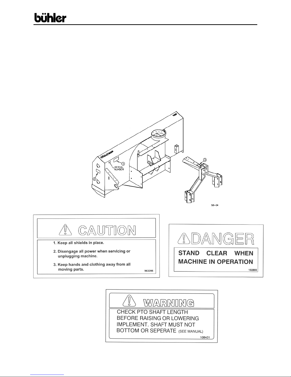
96” Allied Snowblower
WARRANTY REGISTRATION AND POLICY
Buhler Manufacturing products are warranted for a period of twelve (12) months from
original date of purchase, by original purchaser, to be free from defects in material and
workmanship under correct, normal agricultural use and proper applications.
Buhler Manufacturing’s obligations under this warranty shall be limited to the repair or
exchange, at Buhler Manufacturing’s option, of any Buhler Manufacturing product or
part which proves to be defective as provided. Buhler Manufacturing reserves the right
to either inspect the product at the buyer’s location or have it returned to the factory for
inspection.
The above warranty does not extend to goods damaged or subject to accident, abuse or
misuse after shipment from Buhler Manufacturing’s factory, nor to goods altered or
repaired by anyone other than an authorized Buhler Manufacturing representative.
Buhler Manufacturing makes no Express Warranties other than those, which are
specifically described. Any description of goods, including any references and
specifications in catalogues; circulars and other written material published, is for the
sole purpose of identifying goods and shall conform to such descriptions. Any sample
or model is for illustrative purposes only and does not create an Express Warranty that
the goods conform to sample or model shown.
The purchaser is solely responsible for determining suitability of goods sold. This
warranty is expressly in lieu of all other warranties expressed or implied. Buhler
Manufacturing will in no event be liable for any incidental or consequential damages
whatsoever. Nor for any sum in excess of the price received for the goods for which
liability is claimed.
WARRANTY CLAIMS:
Warranty requests must be prepared on Buhler Manufacturing Warranty Claim Forms
with all requested information properly completed. Warranty Claims must be submitted
within a thirty (30) day period from date of failure repair.
WARRANTY LABOR:
Any labor subject to warranty must be authorized by Buhler Manufacturing. The labor
rate for replacing defective parts, where applicable, will be credited at a rate determined
by the Company, Buhler Manufacturing.
IMPORTANT FACTS:
Buckets and Bucket Tines Carry No Warranty
Bent Spears Carry No Warranty
Snowblower Fan Shafts Carry No Warranty
Mower Blades Carry No Warranty
Portable Auger Parts Have Two (2) Year Warranty
- 1 -