Burleigh PCS-6000 Series User manual

-~
ARTISAN
®
~I
TECHNOLOGY
GROUP
Your definitive source
for
quality
pre-owned
equipment.
Artisan Technology
Group
Full-service,
independent
repair
center
with
experienced
engineers
and
technicians
on staff.
We
buy
your
excess,
underutilized,
and
idle
equipment
along
with
credit
for
buybacks
and
trade-ins
.
Custom
engineering
so
your
equipment
works
exactly as
you
specify.
•
Critical
and
expedited
services
•
Leasing
/
Rentals/
Demos
• In
stock/
Ready-to-ship
•
!TAR-certified
secure
asset
solutions
Expert
team
ITrust
guarantee
I
100%
satisfaction
All
tr
ademarks,
br
a
nd
names, a
nd
br
a
nd
s a
pp
earing here
in
are
th
e property of
th
e
ir
r
es
pecti
ve
ow
ner
s.
Find the Thorlabs / Exfo / Burleigh PCS-6000 at our website: Click HERE

OPERATING MANUAL
PCS-6000 SERIES
Motorized Patch-Clamp
Micromanipulator
035-00266 (Rev. 0)
Artisan Technology Group - Quality Instrumentation ... Guaranteed | (888) 88-SOURCE | www.artisantg.com

All rights reserved. No part of this publication may be reproduced, stored in a
retrieval system, or transmitted in any form, be it electronically, mechanically
or by any other means such as photocopying, recording or otherwise, without
the prior written permission of EXFO Photonic Solutions Inc. (EXFO).
Information provided by EXFO is believed to be accurate and reliable.
However, no responsibility is assumed by EXFO for its use or for any
infringements of patents or other rights of third parties that may result from
its use. No license is granted by implication or otherwise under any patent
rights of EXFO.
The information contained in this publication is subject to change without
notice.
© 2007 EXFO Photonic Solutions Inc.
Words that EXFO considers trademarks have been identified as such. EXFO®,
Burleigh®and Gibraltar®are registered trademarks. However, neither the
presence nor absence of such identification affects the legal status of any
trademark.
Artisan Technology Group - Quality Instrumentation ... Guaranteed | (888) 88-SOURCE | www.artisantg.com

CONTENTS
1. Introduction……………………………………………………………………………………………..1-1
Getting Started ...............................................................................................................................1-1
Overview ..........................................................................................................................................1-1
Major Components .........................................................................................................................1-2
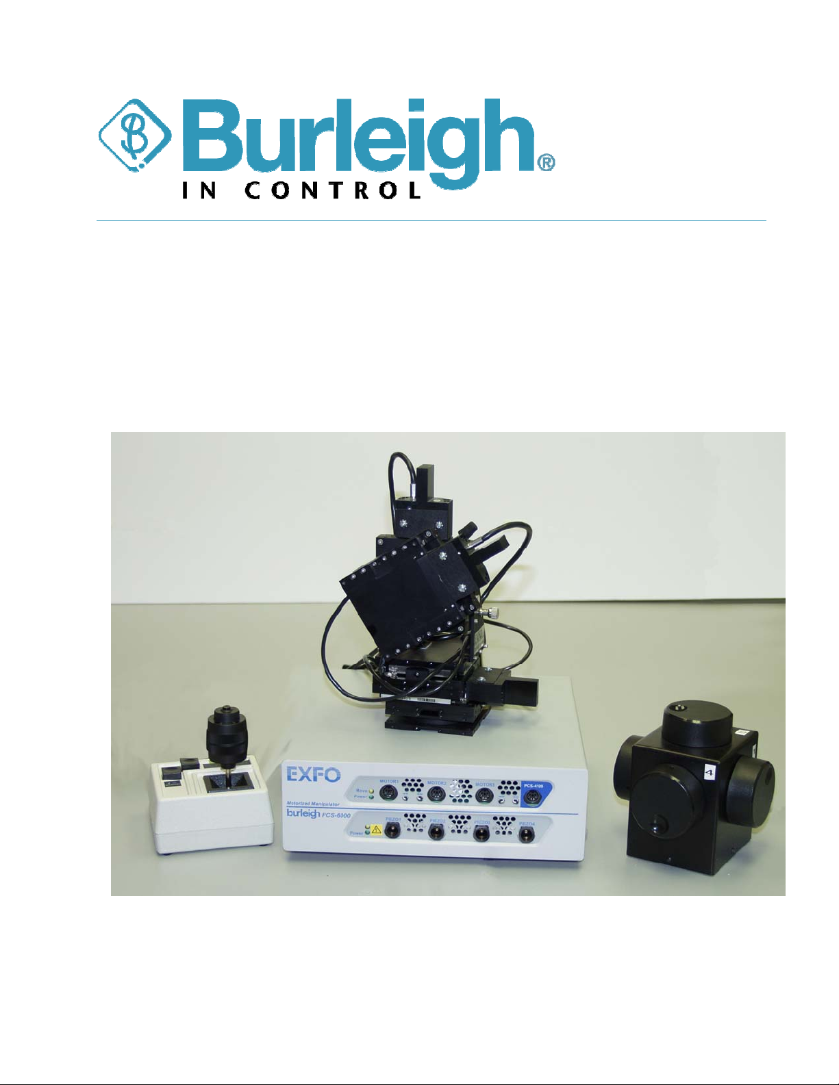
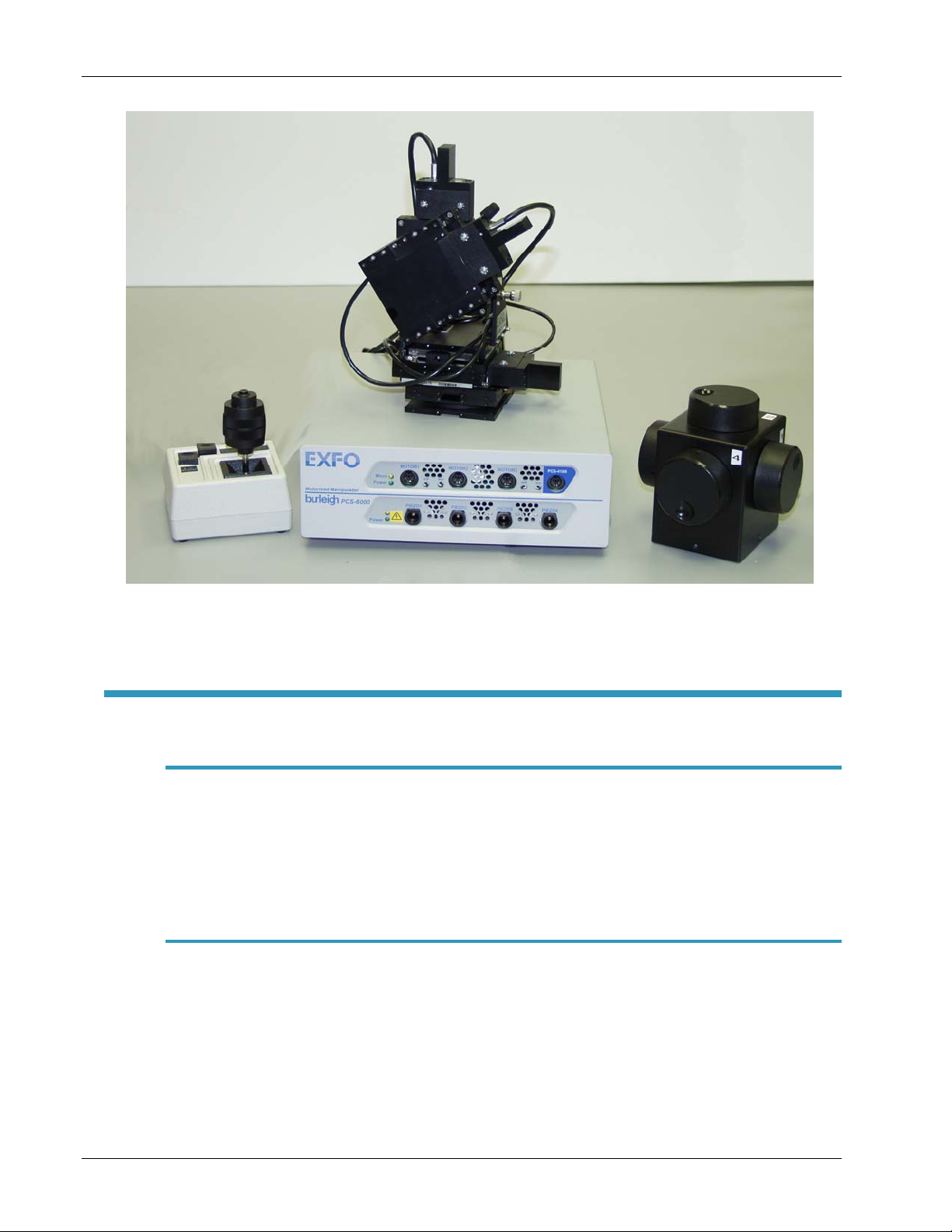
Micromanipulator Assembly .................................................................................................1-2
Axis Control Unit.....................................................................................................................1-2
Joystick.....................................................................................................................................1-3
Controller Unit.........................................................................................................................1-3
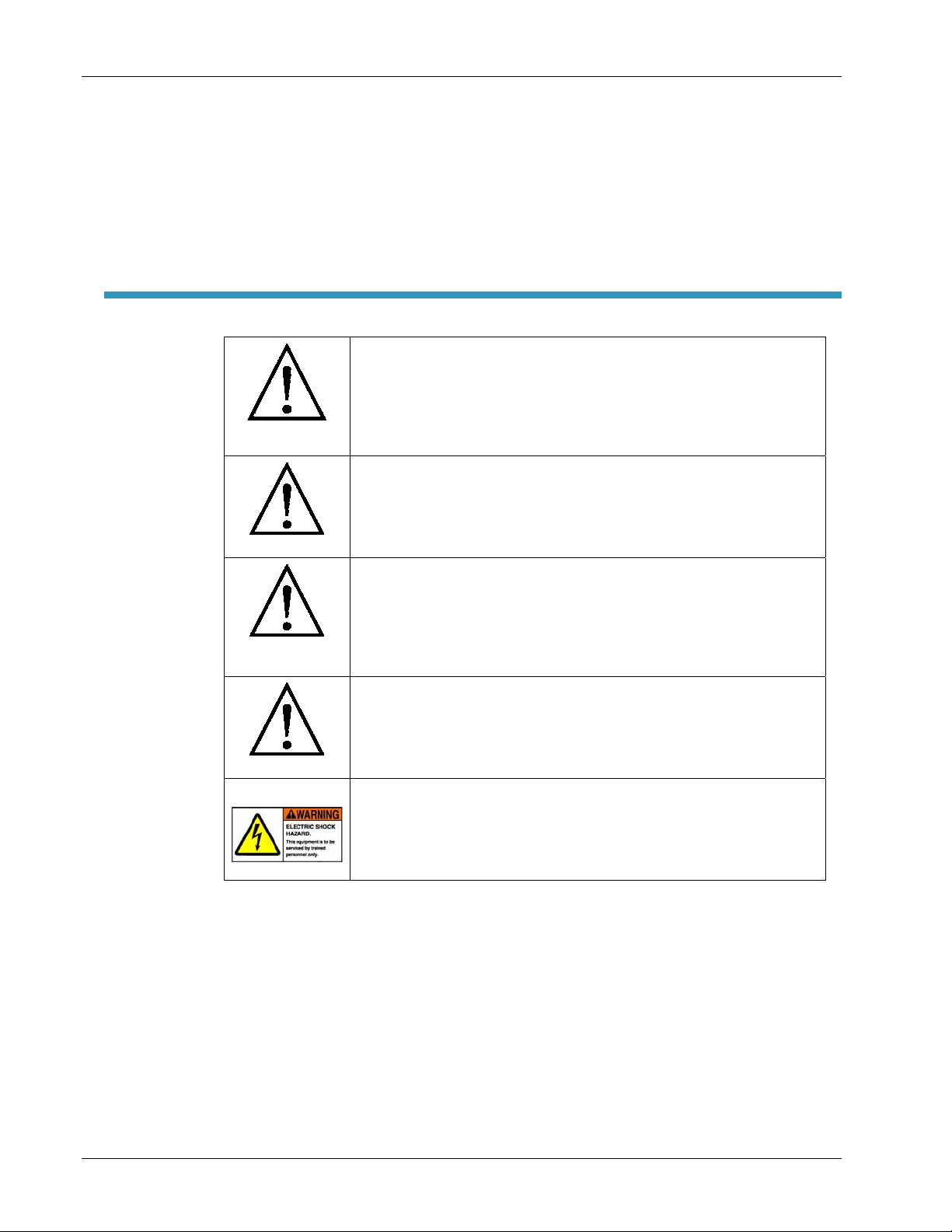
Glossary of Symbols …………………………………….................................................................1-3
Safety Warnings .............................................................................................................................1-4
2. Description……………………………………………………………………………………………….2-1
Mechanisms of Motion .......................................................................................................................2-1
Coarse Motion .........................................................................................................................2-1
Fine Motion ..............................................................................................................................2-1
Configurations ....................................................................................................................................2-2
Axes of Motion ...........................................................................................................................2-2
Right and Left Configurations ..............................................................................................2-3
Manipulator Configurations ..................................................................................................2-3
3. Orientation……………………………………………………………………………………………….3-1
Control Unit......................................................................................................................................3-1
Front Panel...............................................................................................................................3-1
Rear Panel………………………………………………………………………………………….....3-3
Axis Control Unit (ACU).................................................................................................................3-4
Joystick .............................................................................................................................................3-5
Graphical User Interface…………………………………………………………………………………3-6
Serial Port Communication………………………………………………...................................3-11
4. Installation ..................................................................................................................................4-1
Unpacking the Unit.........................................................................................................................4-1
Removing the Shipping Clips .......................................................................................................4-1
Mounting the Manipulator.............................................................................................................4-2
Connecting the Cables...................................................................................................................4-2
Mounting a Headstage and Pipette.............................................................................................4-3
5. Operation.....................................................................................................................................5-1
Powering Up and Checking for Motor Motion ...........................................................................5-1
Positioning Under the Microscope and Checking for Piezo Motion.......................................5-1
Adjusting the Approach Axis Angle ............................................................................................5-2
Setting the Adjustable Stop .........................................................................................................5-3
Operational Hints............................................................................................................................5-3
Joystick Control.......................................................................................................................5-3
Piezo Control ...........................................................................................................................5-4
Artisan Technology Group - Quality Instrumentation ... Guaranteed | (888) 88-SOURCE | www.artisantg.com

Single Stepping ...................................................................................................................... 5-4
Drift Problems......................................................................................................................... 5-4
6. Maintenance ............................................................................................................................... 6-1
Overview of Maintenance Required............................................................................................ 6-1
Maintenance Schedule .......................................................................................................... 6-1
Lubricating Motor Shafts ...................................................................................................... 6-1
Electronic Maintenance......................................................................................................... 6-6
Replacing the Fuse(s) ........................................................................................................... 6-6
Adjusting the Friction of the ACU Knobs................................................................................... 6-7
Adjusting the Friction and Eliminating Lateral Play in the Manual Adjustment Knobs ... 6-8
Troubleshooting.............................................................................................................................. 6-9
Problem: Excess motion of pipette tip during manual adjustment ........................... 6-9
Problem: No fine motion................................................................................................... 6-10
Problem: No coarse motion.............................................................................................. 6-11
Problem: Drift...................................................................................................................... 6-12
7. Specifications ............................................................................................................................. 7-1
Performance: .......................................................................................................................... 7-1
Environmental Specifications:............................................................................................. 7-1
Product Safety: ...................................................................................................................... 7-2
WEEE Directive Compliance:................................................................................................7-3
Warranty
Index
Artisan Technology Group - Quality Instrumentation ... Guaranteed | (888) 88-SOURCE | www.artisantg.com

Burleigh PCS-6000 Series Operating Manual 1 Introduction
EXFO Life Sciences & Industrial Division
1-1
1. INTRODUCTION
Getting Started
Thank you for purchasing a PCS-6000 Series motorized manipulator. This
manual is intended to provide in-depth information on the operation and use
of the PCS-6000.
Overview
Burleigh PCS-6000 Series patch-clamp micromanipulators from EXFO Life &
Industrial Division are ultra-stable, high-resolution positioning systems
designed for patch clamp recording. EXFO has incorporated more than 20
years of experience and knowledge in piezoelectric actuators, precision
mechanics and electronic control to create a system that maximizes your
research productivity.
The Burleigh PCS-6000 micromanipulator is mounted on or next to your
microscope. Your headstage and pipette are mounted to the Burleigh PCS-
6000 so that the end of the pipette is in the field of view of the microscope.
The Burleigh PCS-6000 provides rapid motorized positioning with travel range
of about 25 mm and steps as small as 5 µm. After preliminary positioning
with the motors, fine positioning is obtained by using piezo actuators, with
150 µm or 300 µm travel. Special rotational adjustments are incorporated to
allow optimum pipette working angle and easy pipette exchange. The
Burleigh PCS-6000 is modular and allows numerous configurations so that it
can be customized for each user.
The motor is controlled by a joystick that is separate and distinct from the
fine motion control. The farther the joystick is moved from its rest position,
the faster the stage moves. The fastest speed attainable is 2 mm/second.
The fine motion of the piezo is controlled by the position of a large knob on
the axis control unit (ACU). The knobs can be turned through 1080 degrees
(three revolutions) to sweep the entire range of the piezo movement, either
150 or 300 µm. When the knob is left in a specific position, motion stops.
While the Burleigh PCS-6000 was designed for patch clamp recording, the
characteristics of the instrument are useful for many other applications
requiring high-precision positioning capabilities.
Artisan Technology Group - Quality Instrumentation ... Guaranteed | (888) 88-SOURCE | www.artisantg.com

Burleigh PCS-6000 Series Operating Manual 1 Introduction
EXFO Life Sciences & Industrial Division
1-2
Figure 1-1: PCS-6000 Series patch-clamp micromanipulator
Major Components
Micromanipulator Assembly
The micromanipulator assembly consists of up to four linear stages and two
rotary pivot stages assembled with a 90°bracket. Depending on the
configuration, the linear stages can have no piezo, a 150 µm piezo or a 300
µm piezo, no long-travel adjustment mechanism, a manual long travel
adjustment screw or a motor.
Axis Control Unit
The axis control unit (ACU) is a rectangular box with large rotary knobs that
control the position of the piezo actuators. Normally it is placed next to the
microscope.
Axis Control
Unit
(
ACU
)
Joystick
Artisan Technology Group - Quality Instrumentation ... Guaranteed | (888) 88-SOURCE | www.artisantg.com

Burleigh PCS-6000 Series Operating Manual 1 Introduction
EXFO Life Sciences & Industrial Division
1-3
Joystick
The joystick controls the speed and direction of the servo motors. The joystick
assembly also includes switches to activate specific functions.
Controller Unit
The control unit contains the electronics that drive the piezo and the servo
motors.
Glossary of Symbols
The following safety related symbols are used on this product and throughout
this manual:
CAUTION – RISK OF DANGER
Consult accompanying documentation prior to
operation
CAUTION
Risk of Electrical Shock – Do not remove cover, no
user serviceable parts inside
CAUTION
Indicates a potentially hazardous situation that, if
not avoided, may result in component damage. Do
not proceed unless you understand and meet the
required conditions.
Chassis Ground
Motor Direction Switch
Input/Output Control Signal
Fuses – User Replaceable
Safety Ground
Artisan Technology Group - Quality Instrumentation ... Guaranteed | (888) 88-SOURCE | www.artisantg.com

Burleigh PCS-6000 Series Operating Manual 1 Introduction
EXFO Life Sciences & Industrial Division
1-4
Safety Warnings
WARNING
Should this equipment be used in a manner not specified
by EXFO, the protection provided by the equipment may
be impaired. Always follow the operating instructions as
indicated!
WARNING
Refer servicing to qualified personnel. To prevent
electrical shock, do not open or remove the cover of the
controller or joystick.
WARNING
IEC Class I Product: Use only the 3-prong AC power cord
supplied with this equipment. Always insert the power
cord into an electrical outlet provided with a protective
earth contact.
WARNING
To reduce the risk of fire or shock, always replace the
fuses with the same type and rating. Always detach the
power supply cord prior to attempting to replace fuses!
WARNING
This unit contains high voltage components. It is
recommended that only qualified technical personnel
perform testing or repairs.
Artisan Technology Group - Quality Instrumentation ... Guaranteed | (888) 88-SOURCE | www.artisantg.com

Burleigh PCS-6000 Series Operating Manual 2 Description
EXFO Life Sciences & Industrial Division
2-1
2. DESCRIPTION
Mechanisms of Motion
PCS-6000 linear stages integrate piezo-flexure assemblies inside crossed
roller bearing linear stages with a stepping motor for coarse motion. The
joystick is used to control the coarse motion. A large knob on the axis control
unit (ACU) controls the fine positioning obtained by use of a piezo. Two
rotary pivot stages are incorporated into the manipulator to allow optimum
adjustment of the pipette working angle and easy pipette exchange.
Coarse Motion
Coarse motion is provided by a stepping (servo) motor attached to the linear
translation stage. The motor is controlled by a joystick that has a “dead
zone” in the rest position. This is a safety feature so that a small accidental
touch does not cause motion. The farther away from the neutral position the
joystick is moved, the faster the motor moves the stages. The direction of
motion of the motor is controlled by the direction of the joystick motion. It is
possible to move along a diagonal line if the joystick is moved along a
diagonal.
With a bit of practice an experienced operator can learn to position the pipette
to within about 15 µm of the target with the coarse motion provided by the
motor.
Fine Motion
The piezo-flexure stages integrated into the linear stage provide fine motion.
These stages contain a piezoelectric ceramic element that expands when a
voltage is applied across it. The piezoelectric element is mounted in a
specially machined metal body that provides amplification of the motion.
Artisan Technology Group - Quality Instrumentation ... Guaranteed | (888) 88-SOURCE | www.artisantg.com

Burleigh PCS-6000 Series Operating Manual 2 Description
EXFO Life Sciences & Industrial Division
2-2
PIEZO GENERATES
FINE MOTION BY
EXPANDING/CONTRACTING MOTOR GENERATES COARSE
MOTION BY MOVING ALONG SHAFT
STAGE TOP (ATTACHED TO MOTOR)
TOTAL MOTION = SUM OF COARSE AND FINE MOTIONS
FINE COARSE
FINE + COARSE
= TOTAL MOTION
MOTOR
SHAFT
FIXED
STAGE
BOTTOM
Figure 2-1: Section view of stage and piezo showing the additive nature
The voltage applied to the piezoelectric ceramic element is controlled by the
position of the large knob on the ACU. The large knob is connected to a
three-turn potentiometer (variable resistor). The expansion of the
piezoelectric element is determined solely by the position of the knob. Thus,
the motion of the stage follows the position of the knob. The motion is
instantaneous and stops as soon as the knob is left in a single position.
Configurations
The PCS-6000 is a modular system. Different configurations are available for
the linear stages. Stages normally are configured with a motor and either 150
or 300 µm piezos. Alternatives to the normal configurations are those that
have coarse motion provided by a manual adjusting screw or no coarse
motion all. It is possible to get coarse motion only with no fine piezo motion.
Axes of Motion
The four axes correspond to the following motions.
Axis
number Axis name Motion type
1 X Front to back from operator’s perspective
2 Y Left and right from the operator’s perspective
3 Z Vertical (up and down)
4 Approach Angled (adjustable) axis that the head stage attaches to
Artisan Technology Group - Quality Instrumentation ... Guaranteed | (888) 88-SOURCE | www.artisantg.com

Burleigh PCS-6000 Series Operating Manual 2 Description
EXFO Life Sciences & Industrial Division
2-3
Figure 2-2: Graphic representation of axes
Right and Left Configurations
A right-hand configuration is used when the manipulator is placed on the right
of the microscope. The manipulator is assembled such that the approach axis
projects to the left and the rotary stage locking knobs are conveniently
located on the outboard (right) side of the manipulator. The left-hand
configuration essentially is a mirror image of the right hand.
Manipulator Configurations
PCS-6100
This configuration has three orthogonal axes:
Axis 1 – front to back
Axis 2 – left to right
Axis 3 – vertical
Axis 1 and Axis 2 have manual knobs only with no piezo elements and no
motors. Axis 3 has a motor and a 150-µm piezo. It is available in both right-
and left-hand configurations.
In addition, there are two rotary stages – one that rotates in the horizontal
plane and one in the vertical plane.
Approach
X Y
Z
Artisan Technology Group - Quality Instrumentation ... Guaranteed | (888) 88-SOURCE | www.artisantg.com

Burleigh PCS-6000 Series Operating Manual 2 Description
EXFO Life Sciences & Industrial Division
2-4
PCS-6100
RIGHT HANDED
VERSION
PCS-6100
LEFT HANDED
VERSION
Figure 2-3: PCS-6100
PCS-6200
This configuration has three axes:
Axis 1 – front to back
Axis 3 – vertical
Axis 4 – approach
All three axes have the motorized linear stages with 150-µm piezo elements.
In addition, there are two rotary stages – one that rotates in the horizontal
plane and one in the vertical plane.
PCS-6200
RIGHT HANDED
VERSION
PCS-6200
LEFT HANDED
VERSION
Figure 2-4: PCS-6200
Artisan Technology Group - Quality Instrumentation ... Guaranteed | (888) 88-SOURCE | www.artisantg.com

Burleigh PCS-6000 Series Operating Manual 2 Description
EXFO Life Sciences & Industrial Division
2-5
PCS-6300
This configuration has three axes.
Axis 1 – front to back
Axis 3 – vertical
Axis 4 – approach
All three axes have motorized linear stages. Axis 1 and Axis 3 have 150-µm
piezo elements while Axis 4 has 300-µm piezo element.
In addition, there are two rotary stages – one that rotates in the horizontal
plane and one in the vertical plane.
PCS-6300
LEFT HANDED
VERSION
PCS-6300
RIGHT HANDED
VERSION
Figure 2-5: PCS-6300
PCS-6400
This configuration has three axes.
Axis 1 – front to back
Axis 3 – vertical
Axis 4 – approach
All three axes have the motorized linear stages with 300-µm piezo elements.
In addition, there are two rotary stages – one that rotates in the horizontal
plane and one in the vertical plane.
Artisan Technology Group - Quality Instrumentation ... Guaranteed | (888) 88-SOURCE | www.artisantg.com

Burleigh PCS-6000 Series Operating Manual 2 Description
EXFO Life Sciences & Industrial Division
2-6
PCS-6400
LEFT HANDED
VERSION
PCS-6400
RIGHT HANDED
VERSION
Figure 2-6: PCS-6400
PCS-6500
This configuration has four axes:
Axis 1 – front to back
Axis 2 – left to right
Axis 3 – vertical
Axis 4 – approach
Axis 1 and Axis 2 have motorized linear stages only. Axis 3 has a motor and
150-µm piezo element. Axis 4 has a 150-µm piezo element with no coarse
motion.
PCS-6500
RIGHT HANDED
VERSION
PCS-6500
LEFT HANDED
VERSION
Figure 2-7: PCS-6500
Artisan Technology Group - Quality Instrumentation ... Guaranteed | (888) 88-SOURCE | www.artisantg.com

Burleigh PCS-6000 Series Operating Manual 2 Description
EXFO Life Sciences & Industrial Division
2-7
Additional configurations
Non-standard configurations are available by special order from the factory.
Their product designation is PCS6000 – (XXXX). Special order configurations
permit the combination of options to suit the exact experiment. Coarse and
fine positioning options are listed in the table below.
Coarse Positioning
Options
Fine Positioning
Options
Motorized 300 µm
Manual 150 µm
Fixed at center No fine positioning
Rotary Pivot Stage
Each PCS-6000 manipulator comes with two rotary pivot stages with
adjustable stops (Figure 2-8). One is on the very bottom of the manipulator
and allows for rotation in the X – Y plane (parallel to Z axis). The other is
mounted to the moving portion of the vertical axis and allows for rotation in
the Y – Z plane (parallel to the X axis). The rotary pivot stages enable the
operator to rotate away to perform a task such as replace a pipette and then
return very close to the original set point.
Figure 2-8: Rotary pivot stage with adjustable stop mechanism
Artisan Technology Group - Quality Instrumentation ... Guaranteed | (888) 88-SOURCE | www.artisantg.com

Artisan Technology Group - Quality Instrumentation ... Guaranteed | (888) 88-SOURCE | www.artisantg.com

Burleigh PCS-6000 Series Operating Manual 3 Orientation
EXFO Life Sciences & Industrial Division
3-1
3. ORIENTATION
Control Unit
The control unit supplies the drive signals to both the piezo actuators and the
drive motors. The drive board for the motors is on top layer. The drive board
for the piezo actuators is on the bottom.
Front Panel
Figure 3-1: Front panel of control unit
Motor Control Board
There are four receptacles for motors on the motor control board. The motor
drive circuits are identical in all four channels. The motors should be plugged
into their corresponding receptacle. The motors are stepping motors with a
base micro-step of step of 1.6 µm. The direction of the motor travel can be
reversed by the small toggle switch next to the receptacle.
The motor control board has two lights on it. The green Power light indicates
that the power to the board is on and that the board has completed its power
on routine. The yellow Move light is lit only when one or more motors are
being told to move.
When the joystick is displaced from its rest position, the microprocessor on
the motor board provides the proper current drive waveforms to the motor
causing it to move in the direction indicated by the joystick deflection. Within
about ½ second after the joystick is returned to its rest position, the current
to the motor shuts down to a very minute holding current. This prevents the
loss of position.
If an axis is commanded to move beyond its physical limits in either direction,
the axis motion stops but the motor continues to turn. This is called a “stall”
condition and does not harm the motor as long as the motor does not remain
in the stalled condition for a significant period of time (more than 15
Power On
indicators
Motors moving
indicator
Motor
module
Motor direction
switches
Piezo
module
Artisan Technology Group - Quality Instrumentation ... Guaranteed | (888) 88-SOURCE | www.artisantg.com

Burleigh PCS-6000 Series Operating Manual 3 Orientation
EXFO Life Sciences & Industrial Division
3-2
seconds). Stall is detected by noticing that the Move light is on, but no
motion is detected. The motor generates a clicking sound while in stall.
Several configurations of the PCS-6000 have less than four motors. In these
instances, there are unused motor receptacles. There is no need to do
anything special with these unused connections because they are inactive
without a motor plugged into them.
Servo Motor Control Memory Options
The controller is available with 2 different memory options:
The “T” type configuration provides 2 memory presets which are functional on
the manipulator stage connected to “Motor 2” input on the controller front
panel. This is typically used on the manipulator for the Approach axis. This
controller setting can be verified by 2 audible beeps when the controller is
powered up.
The “C” type configuration provides 2 memory presets which are functional on
the manipulator stage connected to “Motor 3” input on the controller front
panel. This is typically used on the manipulator for the Z (vertical) axis. This
controller setting can be verified by 3 audible beeps when the controller is
powered up.
CAUTION
Never connect or disconnect the cables when the unit is on.
This could cause an arc and damage to the control unit.
Piezo Control Board
The piezo control board is the lower board in the PCS-6000 control chassis. It
has four receptacles for piezo units. Depending on the position of the knob
on the ACU box, a voltage between 0 and 60 V DC is applied to the piezo unit.
Several configurations of the PCS-6000 have less than four piezo units. In
these instances, there are unused piezo receptacles.
WARNING
Dangerous voltage may be
present. Do not plug anything
into the piezo receptacle when
the unit is turned on. Ensure the
unit is turned off before
connecting any piezo cables.
Artisan Technology Group - Quality Instrumentation ... Guaranteed | (888) 88-SOURCE | www.artisantg.com

Burleigh PCS-6000 Series Operating Manual 3 Orientation
EXFO Life Sciences & Industrial Division
3-3
Rear Panel
Figure 3-2: Rear panel of control unit
Operating Voltage
The unit contains a universal power supply. No changes are needed to switch
from 110V AC 60 Hz to another allowed voltage and frequency (see Section 7,
Specifications for details).
The power switch uses the IEC standard symbols to indicate power condition -
|is ON, and Ois off. See Section 6, Maintenance for fuse replacement.
Chassis Ground
The three-way binding post is part of the chassis ground to the PCS-6000.
The chassis of the PCS-6000 is connected to the safety ground in the line
cord.
Joystick and ACU Connections
The joystick and the ACU plug into their respective connections on the back of
the unit.
Power cord
receptacle
Fuse holder
Chassis
Ground
Post
USB Port
(GUI)
Joystick
Controller:
Motors Axes
1-3
Optional
Controller:
Motor-Axis 4
ACU
Controller:
(Piezo)
Artisan Technology Group - Quality Instrumentation ... Guaranteed | (888) 88-SOURCE | www.artisantg.com
This manual suits for next models
5
Table of contents