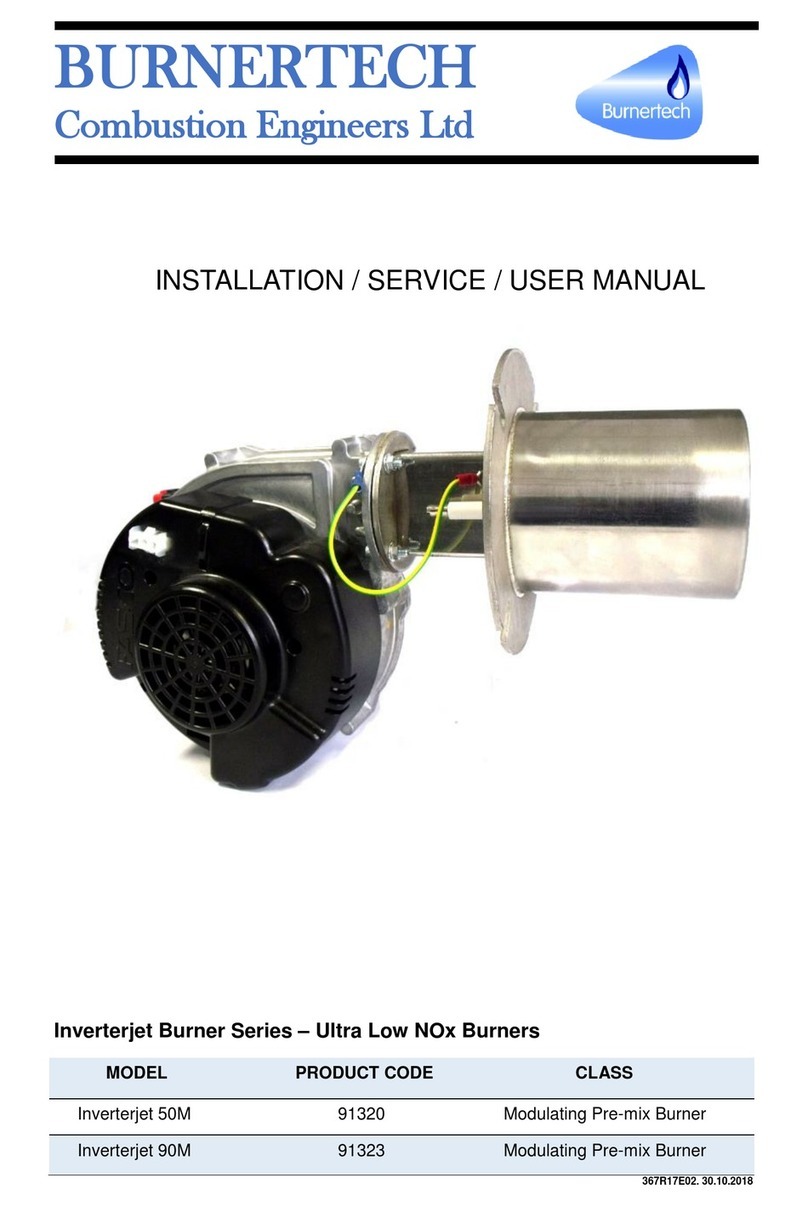
Burnertech INVERTERJET M Series Manual

BURNERTECH
Combustion Engineers Ltd
INSTALLATION / SERVICE / USER MANUAL
I
IN
NV
VE
ER
RT
TE
ER
RJ
JE
ET
T
M
M
S
SE
ER
RI
IE
ES
S
99043 (1) 28/11/2019, Subject to Modifications.
MODEL
PRODUCT CODE
CLASS
INVERTERJET 30M/L
91353
MODULATING PRE-MIX BURNER
INVERTERJET 30M/N
91354
MODULATING PRE-MIX BURNER
INVERTERJET 50M/L
91320
MODULATING PRE-MIX BURNER
INVERTERJET 50M/N
91330
MODULATING PRE-MIX BURNER
INVERTERJET 90M/L
91323
MODULATING PRE-MIX BURNER
INVERTERJET 90M/N
91329
MODULATING PRE-MIX BURNER

Installation / Service / User Manual BURNERTECH
1
Content
1Declaration ................................................................................................................................................. 2
2Technical Information ................................................................................................................................ 4
2.1 Technical Data .................................................................................................................................. 4
2.2 Technical Description of the Burner Parts........................................................................................ 4
2.3 Burner dimensions and weight.......................................................................................................... 5
2.4 Burner operation ............................................................................................................................... 6
2.4.1 Control operation........................................................................................................................ 6
2.4.2 Basic sequence of operation.................................................................................................... 6
2.4.2.1 Burner Program.................................................................................................................... 6
3Installation.................................................................................................................................................. 7
3.1 General Installation Information....................................................................................................... 7
3.2 Burner Mounting............................................................................................................................... 8
3.2.1 Standard Burner Mounting Detail............................................................................................ 8
3.3 Gas Installation ................................................................................................................................. 9
3.4 Electrical Installation .......................................................................................................................10
3.5 Basic Electrical Safety .....................................................................................................................10
3.5.1 Burner Wiring Diagrams –Inverterjet M Series....................................................................11
4Commissioning......................................................................................................................................... 12
4.1 Commissioning procedure ...............................................................................................................12
4.1.1 Turning on the Burner ..............................................................................................................13
4.1.2 Commissioning operation ........................................................................................................13
4.1.2.1 Maximum rate CO2...........................................................................................................13
4.1.2.2 Minimum rate CO2............................................................................................................13
4.1.2.3 Burner Heat Input.............................................................................................................13
4.1.2.4 Burner Sequence .............................................................................................................14
4.1.3 Test Mode ..................................................................................................................................15
4.1.3.1 PC USB Interface................................................................................................................15
5User Instructions....................................................................................................................................... 16
5.1 Limitations on use of Burner............................................................................................................16
5.2 Using the Burner..............................................................................................................................17
5.2.1 Start up.......................................................................................................................................17
5.2.2 Stand-by Mode..........................................................................................................................17
5.2.3 Heating Mode ............................................................................................................................17
5.2.4 Burner operation .......................................................................................................................17
6Servicing................................................................................................................................................... 18
6.1Service Inspection............................................................................................................................18
6.1.1 The condition of the burner head............................................................................................18
6.1.2 The condition of the electrodes...............................................................................................18
6.1.3 The condition of the electrical circuits....................................................................................18
6.2 Service operation..............................................................................................................................19
6.2.1 Re-assembly..............................................................................................................................19
6.3 Fault Finding....................................................................................................................................20
6.3.1 Lockouts/Blockings...................................................................................................................20
6.3.1.1 Lock-out reset .....................................................................................................................20
6.3.2 Maintenance Notes...................................................................................................................21

Installation / Service / User Manual BURNERTECH
2
1 Declaration
The Inverterjet burners are state of the art burner system.
Designed with imagination and passion. It utilises the very latest technology to provide a reliable,
hot, clean and compact gas heating solution.
A truly market leading product which is quite simply;
‘Taking Burner Technology into the 21st Century’.
Please read this manual before Unpacking and Installing the Burner.
For Burner Installation/ Operation advise please contact Burnertech
To ensure maximum product reliability, we advise and request that a Burnertech Approved
Engineer who has attended our product course conducts the 1st burner commissioning.
For Training, Service or Commissioning information please contact Burnertech
This manual is provided as an integral part of the equipment and its delivery to the end user is
essential.
Please keep this manual for future reference, more copies of this manual are available upon
request. It is possible to download this Manual and Technical Datasheet from the
www.burnertech.co.uk Burnertech Website.
CONTACT / SERVICE:
Unit C Lostock Industrial Estate,
Lostock Lane,
BL6 4BL,
Bolton, United Kingdom.
Tel: +44 (0)1204 393222
Fax: +44 (0)1204 394222
Website: www.burnertech.co.uk

Installation / Service / User Manual BURNERTECH
3

Installation / Service / User Manual BURNERTECH
4
2 Technical Information
2.1 Technical Data
INVERTERJET MODEL
30M/L
30M/N
50M/L
50M/N
90M/L
90M/N
Type
Pre-Mix Burner
Pre-Mix Burner
Pre-Mix Burner
Fuel Type
LPG
NG
LPG
NG
LPG
NG
Power
Min
kW
6
10
18
Max
kW
30
50
90
Modulation Range
1:5
1:5
1:5
Nominal Voltage
VAC
230
230
230
Frequency
Hz
50/60
50/60
50/60
Phase
1 ~
1 ~
1 ~
Fan Current Draw
Max
A
0.3
1.9
1.9
Gas Connection Flange Size
1/2 “BSP
1/2 “BSP
1/2 “BSP
Gas Inlet Pressure
Min
mbar
10
10
10
Max
mbar
60
60
60
2.2 Technical Description of the Burner Parts
The Burners in the Inverterjet M series have the following technical description of
the parts.
1 Burner Mounting Plate
2 Ignition Electrode
3 Ionisation Probe
4 Gas Connection Flange
5 Pressure Feedback Connector
6 Offset Adjustment Screw
7 Reset Button
8 Indicator Light (Alarm)
9 Burner Controller
10 Throttle Adjustment Screw
11 Fan Housing
12 Burner Head Earth Connector
13 Burner Head
14 Gas Valve
15 Venturi

Installation / Service / User Manual BURNERTECH
5
2.3 Burner dimensions and weight
The diagrams below show the major dimensions and weight of the burner.
MODEL
A
B
C
D1
D2
E
H
L
W
Weight
mm
mm
mm
mm
mm
mm
mm
mm
mm
kg
Inverterjet 30M/L
89
71
91
Ø101.6
Ø170
133
218
361
225
5.2
Inverterjet 30M/N
89
71
91
Ø101.6
Ø170
133
218
361
225
5.2
Inverterjet 50M/L
92
71
91
Ø101.6
Ø170
164
244
365
238
5.6
Inverterjet 50M/N
92
71
91
Ø101.6
Ø170
164
244
365
238
5.6
Inverterjet 90M/L
92
71
121
Ø101.6
Ø170
164
244
395
238
5.9
Inverterjet 90M/N
92
71
121
Ø101.6
Ø170
164
244
395
238
5.9

Installation / Service / User Manual BURNERTECH
6
2.4 Burner operation
2.4.1 Control operation
The microprocessor-based burner controller is made for fan assisted, direct burner ignition
applications.
The control powers the gas valve and DC-fan. Normal heat demand is given by a 230 VAC switch
input (depending on the model)
After heat demand and successful ignition, modulation can be controlled by external 0 - 10V or
4 - 20mA signal.
2.4.2 Basic sequence of operation
The Normal Heating mode is started when the High Voltage Heat Demand input is closed. When
ignition is successful, the fan can be controlled in a number of ways depending on parameter
setting:
•0-10 V control, a DC voltage between zero and ten volts can be applied to connector (X3
Pins 8 & 16). At zero volt the fan will run on Minimum Fan speed. At ten volt the fan will run
on Maximum Fan speed.
•4-20 mA control, with an external resistor of 500 Ώ1 % placed between connector (X3
Pins 8 & 16), the fan speed can be controlled with a current in the range of 4 to 20 mA.
At 4 mA the fan will run on Minimum Fan speed. At 20 mA the fan will run at Maximum Fan
Speed.
•On/Off control, when the option On/Off control is selected, the fan speed depends on the
fan Slope control parameter: When slope control is off (parameter set to zero), the fan
speed will immediately go to maximum. Otherwise the fan speed will rise from Ignition Fan
speed to Maximum Fan speed with(value)*50 RPM/sec. Slope control works for both
increasing and decreasing of fan speed.
2.4.2.1 Burner Program
NOTE: The Control can be reset by depressing the internal/external reset button

Installation / Service / User Manual BURNERTECH
7
3 Installation
3.1 General Installation Information

Installation / Service / User Manual BURNERTECH
8
3.2 Burner Mounting
To mount the burner, suitable mounting studs or threads for bolts need to be provided for the burner
Mounting Plate. Appropriate dimensions are shown below. When installing the burner, please be
sure to use the gasket provided for sealing and insulating between the Mounting Plate and the
bearing wall of the appliance.
3.2.1 Standard Burner Mounting Detail
1. Burner Head
2. Burner Mounting Gasket
3. Boiler Door
MODEL
C
D1
D2
G
PCD
R
2R
mm
mm
mm
deg.
mm
mm
mm
Inverterjet 30M/L
88
101.6
170
45
Ø 138
4.5
9
Inverterjet 30M/N
88
101.6
170
45
Ø 138
4.5
9
Inverterjet 50M/L
88
101.6
170
45
Ø 138
4.5
9
Inverterjet 50M/N
88
101.6
170
45
Ø 138
4.5
9
Inverterjet 90M/L
118
101.6
170
45
Ø 138
4.5
9
Inverterjet 90M/N
118
101.6
170
45
Ø 138
4.5
9

Installation / Service / User Manual BURNERTECH
9
3.3 Gas Installation
To Install the Gas supply to the Burner, follow the instruction bellow:
1. Remove the seal in front of the Gas connection flange at the rear of the burner
2. Check the thread on the flange and ensure that there is no debris in the threads
3. Connect the corresponding gas pipe/fittings to the Gas connection flange in the Burner.
4. Tighten the gas pipe/fittings and the Gas connection flange securely, ensuring that there is
no possibility for gas leakage.

Installation / Service / User Manual BURNERTECH
10
3.4 Electrical Installation
The electrical wiring diagram for the Burners are shown in the following page.
3.5 Basic Electrical Safety

Installation / Service / User Manual BURNERTECH
11
3.5.1 Burner Wiring Diagrams –Inverterjet M Series
X3 Microfit
*X2 Communication
(see note)
X1 Minifit
NOTE:
In the diagram shown, the X1 Minifit connector contains the High Voltage (230VAC) connections,
and the X3 Microfit connector contains the safety extra low voltage connections.
X2 Microfit connector is used for communication via a dedicated Windows based PC software and
USB lead (Please contact Burnertech for more information).
An Earth must be connected to the 6.3mm spade connector on the gas valve, not to signal ground
on X3
HL must be normally closed for the control to operate, if a Hi Limit stat is not used, then a link must
be fitted between X3.3 and X3.10.
Heat demand is given by 230VAC input.
*For use with dedicated Windows based USB interface, please contact Burnertech for more
information about this option

Installation / Service / User Manual BURNERTECH
12
4 Commissioning
NOTICE
All Inverterjet premix burners are test fired in the factory prior to despatch to the customer.
Whenever possible, Burnertech prefer to pre-set the maximum and minimum fan speed to assist
the commissioning process
In order to ensure maximum product reliability, we advise and request that a Burnertech
approved engineer conduct the 1st burner commissioning. Failure to comply with this
requirement may result to inappropriate burner setting which can lead to damage to property and
injuries to personnel.
4.1 Commissioning procedure
To start the commissioning procedure, follow the steps bellow:
1. Connect a Manometer to the gas inlet pressure test nipple on the burner gas inlet
connection.
2. Locate CO/CO2combustion analyser into flue pipe as close as possible to the appliance
outlet.
3. Confirm and record that adequate ventilation is available for the safe operation of the
burners.
4. Establish that the system pipe work is complete, fully purged and adequate system load
and circulation exists to facilitate firing of the burners.
5. Turn ‘On’ the gas supply and ensure adequate static gas pressure is available at the burner
inlet.
6. Locate the position of the Throttle adjustment screw (High rate throttle adjuster)
7. Locate the position of the Offset adjustment screw (Low rate offset adjuster).
1 Throttle Adjustment Screw
2 Offset Adjustment Screw
3 Reset Button
4 Indicator Light (Alarm)

Installation / Service / User Manual BURNERTECH
13
4.1.1 Turning on the Burner
Turn ‘On’ the main electrical supply and turn on the burner demand interlock/switch.The burner fan
will start and pre-purge. The burner Control will then drive the fan to a pre-set ignition speed. The
ignition spark is generated at this point and the Burner will ignite. The 0-10V temperature control (if
used) will then modulate the Burner to the desired fan speed (output).
4.1.2 Commissioning operation
NOTE: During the burner commissioning, the maximum and minimum fan speeds can be
adjusted if required. The fan speed can be adjusted using the dedicated PC software.
Adjustment of the ignition speed is not recommended as this may affect the reliability of
operation and can only be done using the dedicated PC software.
Since the inverterjet can be used in a multitude of different applications, then the CO2 should be
adjusted to suit the application to which the burner is fitted.
4.1.2.1 Maximum rate CO2
The maximum CO2may be adjusted by use of the throttle screw. turning clockwise decreases the
value and anti-clockwise will increase the value.
8 Adjust the burner output to high fire by increasing the fan speed
9 Measure the flue CO2level and adjust the throttle screw to bring the level to between 9 and
9.5%.
CAUTION
Generally, the CO2should not normally exceed 9.5% on NG or 11% on LPG. We recommend that
the operating CO2is between 0% to +0.5 % higher at maximum fan speed than at minimum.
4.1.2.2 Minimum rate CO2
Minimum CO2 should be adjusted using the offset adjustment screw.
Remove the T40 Torx cap (if present) and turn the screw anti-clockwise to decrease the CO2and
clockwise to increase the CO2. This adjustment should ideally be made with the use of a
micromanometer to help ensure that it is set accurately as this is a sensitive adjustment
10 Adjust the burner output to low fire.
11 adjust the offset adjustment screw (4) to bring the CO2level to between 8.5 and 9%.
12 Changing the high fire setting will affect the low setting but changing the low setting will
have minimal effect on the high setting. It may therefore be necessary to repeat step 9 to 12
several times in order to achieve the acceptable level of CO2at both firing rates.
13 Analyse the flue products on both high and low fire. In both cases, ensure that all readings
(CO2, CO and O2) are within acceptable figures.
4.1.2.3 Burner Heat Input
14 With an appropriate gas meter, conduct a heat input measurement whilst operating at
maximum rate. Ensure the rate is within ±5% of that required for the appliance. If the heat
input is outside the required ±5% tolerance, adjust the fan speed until a satisfactory input is
achieved.
15 Record all combustion input and working gas pressures and return the burner to normal run
condition.

Installation / Service / User Manual BURNERTECH
14
4.1.2.4 Burner Sequence
The following flowchart (Fan speed control flowchart) shows how the fan speed is controlled during
a complete burner sequence. The basic states are:
•Stand-by, fan is off or at Continuous Fan speed when this option is selected;
•Pre-purge;
•Ignition;
•Run state, fan speed is controlled by modulation input, see section “Normal heating mode”.
•Post purge.
The desired fan speed in Continuous and Ignition mode can be independently programmed.
Flow chart –Burner sequence

Installation / Service / User Manual BURNERTECH
15
4.1.3 Test Mode
The test mode can be used to manually control the burner with external communication.
4.1.3.1 PC USB Interface
If required, a windows-based software along with a dedicated USB cable and driver is available to
enable programming of certain parameters in the control and also to read fault codes, etc.
NOTE: Please contact Burnertech for more information relating to this option.
An example screenshot is shown below.

Installation / Service / User Manual BURNERTECH
16
5 User Instructions
5.1 Limitations on use of Burner

Installation / Service / User Manual BURNERTECH
17
5.2 Using the Burner
The controller has the following modes of operation (from lowest to highest priority)
MODES
DESCRIPTION
STAND-BY MODE
When there is no heat demand and error present
HEATING MODE
Activated when high voltage heat demand is given.
TEST MODE
Activated when external test mode heat demand is given
ERROR / FAULT
Any violation of (programmable) limits (and/or internal thermostat
functions) will lead to an error/fault or blocking condition.
5.2.1 Start up
After power On, manual reset each 12/24 hours, the control will perform its start up routine. 12/24
hour reset depends whether a head demand is present. When no heat demand is present, the
control will perform a reset 12 hours after the last one. When a heat demand is present, the control
will wait a maximum of 24 hours to perform the reset.
5.2.2 Stand-by Mode
In Stand-by mode igniter is off, gas valve is closed, and fan is off if fan overrun time is finished and
Continuous Fan speed option is switched off.
5.2.3 Heating Mode
The normal heating mode is started when a high voltage heat demand input is closed. When
ignition is successful, the fan can be controlled between maximum in the following ways depending
on parameter setting:
•0 –10 Volt Control
•4 –20 mA Control
•On/Off Control
5.2.4 Burner operation
Turn ‘On’ the main electrical supply and turn on the burner demand interlock/switch.The burner fan
will start and pre-purge. The burner Control will then drive the fan to a pre-set ignition speed. The
ignition spark is generated at this point and the Burner will ignite.
If satisfactory ignition takes place, the burner will remain alight and the fan speed will modulate in
response to the modulation signal input.
If however satisfactory ignition does not take place, the burner will go through ‘Post-purge’ and
‘Pre-purge’ before re-attempting ‘Ignition’.
This re-cycling will take place three times (depending on the settings) before the burner will enter a
Lock-Out condition which will require manual reset by the user by depressing the Reset button to
restart the burner ignition sequence.
NOTE: The maximum number of remote resets in one hour is five

Installation / Service / User Manual BURNERTECH
18
6 Servicing
A suitably qualified and competent engineer such as a Gas safe/ACS Registered Installer must
carry out all the maintenance operations discussed in this section at least once a year.
In the case of seasonal servicing, it is recommended that the service operations be carried out at
the end of each heating season.
In the case of continuous operation, the service operations should be carried out every six months.
Before removing the burner from the appliance:
1. Ensure you have a replacement burner mounting gasket for re-fitting the burner afterwards.
2. Prepare an appropriately sized and relatively clean and tidy work area to conduct the
maintenance operation.
6.1 Service Inspection
Isolate and disconnect both the gas and electrical supplies from the burner.
Supporting the weight of the burner, carefully remove the fixings securing it to the appliance and
withdraw it from the chamber.
6.1.1 The condition of the burner head
some discolouration of the burner material is normal, but the material should not be cracked or
open. Under no circumstances should any of the perforated holes in the burner tube beneath the
material be visible. Inspect the flange of the burner for any signs of cracking or severe overheating,
which may indicate leakage.
Any serious burner head defect would constitute an ‘Immediate Danger’ and the burner system
SHOULD NOT be put back into operation until adequately repaired.
6.1.2 The condition of the electrodes
Check the ceramics are not cracked or damaged and check that the wire head is still approximately
4mm gap between the Ignition electrode and the burner surface.
DO NOT clean the electrodes and if adjustment is required always try and adjust the wires near to
the ceramic and preferably using a blowtorch to pre-heat the wire.
6.1.3 The condition of the electrical circuits
Check the condition and integrity of the internal burner wiring harness and plugs, ensuring that all
connections are secure. Check that both the ignition and detection leads are in good condition.

Installation / Service / User Manual BURNERTECH
19
6.2 Service operation
Burner head
The burner head should be examined carefully for cracks and/or damage. If there are signs that there has been
over heating of the material or dust on the burner face, the burner head must be removed from the burner.
Close examination of the silver foil at the rear of the inside of the burner head should be done and if all is
okay, the inside of the Inverterjet burner head should be blown out using compressed air.
If the inside of the burner head is found to be severely blocked with dust and dirt please examine
the burner material more closely. It is likely that the burner head material will have overheated due
to the blockage and will be blackened in appearance and may need replacing. If so, the customer
must be advised to protect the burner from dust ingress and/or increase the service intervals.
Electrodes
Inspect the ignition and flame electrodes, if extensive signs of damage are detected, they must then
be removed and replaced.
Fan
The fan is not a serviceable component. Simply ensure it is positively secured and sealed. The
gasket material, electrical plug connections and cover must be secure and in good condition.
The fan case has gas tight seals and the fan casing must never be opened. Due to the 1:1 gas/ air
ratio operating principle of the burner a reduction in fan performance (i.e. dust build up) will not
result in unsafe burner performance.
The gas flow is directly proportional to the air flow therefore any reduction in fan flow would simply
result in a gradual reduction of the appliance heat input.
Venturi Unit
Examine and clean the Venturi unit checking that it is securely attached, and that any gasket is in
good condition. Ensure that any Air Pressure Sensing point is secure and unobstructed (if fitted).
Cleaning: Using a cloth, soft brush and vacuum, carefully remove any dust and grime from the
whole burner assembly taking care not to disturb electrical connections.
6.2.1 Re-assembly
Using a new replacement gasket, carefully and securely slide it to the burner head up until the
gasket and the mounting plate are in contact. carefully refit the burner system into the appliance
combustion chamber and secure using the fixings.
Re-connect gas and electrical connections.
Check for gas soundness as detailed by Local, National Standards and Regulations and turn ‘ON’
the Gas and Electrical supplies.
Finally check and record the combustion and ventilation performance of the burner. Check the basic
operation/control of appliance before restoring automatic control to any Boiler Management System
(if applicable).
This manual suits for next models
6
Table of contents
Other Burnertech Burner manuals
Popular Burner manuals by other brands

Riello
Riello 3479365 Installation, use and maintenance instructions

Heat & Glo
Heat & Glo ST-36TR-IPI owner's manual

Riello
Riello RS 68/E LN Installation, use and maintenance instructions

Monessen Hearth
Monessen Hearth Natural Blaze Series Installation & owner's manual

Octagon
Octagon bio 3 user guide

Riello Burners
Riello Burners Gulliver RS5D Installation, use and maintenance instructions