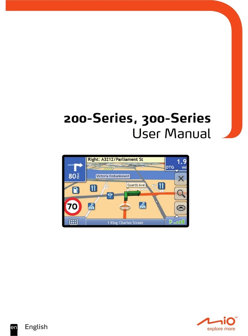
BURY BF 1150 User manual

Socratec Telematic GmbH
We reserve all rights in this document and in the information contained therein. Reproduction, use or disclosure to third parties without express
authority is forbidden. © 2010 ocratec Telematic GmbH.
Guido Hollenstein MA-10-002( ystemManual-XMB).db.odt Page 1/52
Fleetview-XMB
System-Manual

Index
Introduction 2
1. General Remarks 2
2. Security Guidelines 2
3. Scope of Delivery 3
Installation of the telematic module 4
4. Description of the telematic unit 4
5. Position and Mounting 5
6. Connecting the Terminal box 8
7. Installation instructions for the fuses 10
8. Inserting the SD card 11
9. Fitting the SIM card 12
10. Loading the battery 12
First Steps 13
11. The first time you switch the system on 13
12. Switching the system off 13
13. Operating and cleaning the display 14
14. Menu structure 15
Telematic Menu Items 21
15. Tasks 21
16. Messages 21
17. Logbook 22
Navigation Menu Items 23
18. Route Calculation 23
19. Route Calculation with TMC 25
20. Display of Route Navigation 27
21. Additional Symbols in the Display 28
22. The Navigation Menu 29
23. Menu item Route 32
24. Menu item Setup 34
25. Menu item Map 36
26. Menu item TMC, Extras, GPS-Info, Info 37
Hands-Free Set Menu Items 40
27. The
Bluetooth
®
hands-free car kit 40
28. Establishing a
Bluetooth
®
connection 40
29. Description of the menu items 41
30. Disconnect a
Bluetooth
®
connection 42
Further information 43
31. Service 43
32. Approvals and declaration of conformity 44
33. License agreement for final customers 44
34. Information about GNU General Public License (GNU GPL) 47
BF 1150

2
Introduction
1. General Remarks
Dear customer
Thank you for choosing a BURY telematic unit of superior quality which
is very easy and comfortable to use.
In order to enjoy the complete convenience of your new telematic unit,
please read the operating instructions carefully and keep it in your car
for future reference.
If you have further questions regarding installation or use please
contact your specialist dealer. They will be happy to advise you and will
forward your questions and comments to the BURY team. You can also
contact our hotline. Our phone and fax numbers are listed in the chap-
ter Service at the end of the operating instructions.
Have a good trip! – your BURY team
2. Security Guidelines
Installation – who and where
You can easily install your telematic unit yourself. However, please ob-
serve the installation requirements of your car manufacturer (VAS
1978) and please park your car for this purpose at a place where you
don’t obstruct traffic. We recommend that the installation is completed
by a specialist.
Power Supply
The telematic unit is designed for use in both passenger vehicles and
heavy goods vehicles (HGVs).
Disclaimer:
Please comply with country-specific laws and regulations concerning
the e-certifications and the use and installation of electronic systems in
vehicles. If you are not familiar with these, please inform yourself ap-
propriately. If you have any questions on this topic, please do not hesi-
tate to call our hotline.

3
Position, Volume
Make sure you install all components of the navigation system so that
no part or component obstructs your vision while driving. Please also
make sure you install the telematic module well outside all passenger
impact areas in the passenger compartment and also outside the ex-
pansion areas of any airbags in your car. Please follow the guidelines
from your car manufacturer (operating instructions) regarding accesso-
ries. If you have trouble finding the best position for this system in your
car please contact your local car dealer. When adjusting the volume of
the telematic module please make sure you can still hear exterior noise
and the traffic around you.
Operating the navigation system while driving
Please operate the telematic module only when traffic conditions allow
you to do so safely. Please make sure you do not jeopardize, harm,
obstruct or trouble other road users when operating the telematic mo-
dule.
Proper Care
Damage to the telematic module due to lack of proper care may lead to
the loss of warranty claims on this product. Please read the operating
instructions carefully to ensure proper care. Do not expose the device
to moisture and water, extreme temperatures or heavy shocks.
Personal Responsibility
The telematic unit has been designed as a mere navigation aid. Routing
suggestions issued by the system do not release drivers from their duty
to take care nor from their personal responsibility. In all cases, drivers
must obey existing traffic rules and the current traffic situation must be
given priority.
3. Scope of Delivery
The components contained in the scope of the delivery are listed on a
supplementary sheet. Please check that all the components listed on
the sheet are actually contained in the package.
Note:
The telematic unit is sold in different versions with dif-X
ferent components. The operating instructions apply to all
respective versions.
4
On/Off key
Audio-Output
SD cards slot
Reset key
4. Description of the telematic unit
Installation of the telematic module
USB port
SIM cards slot
Contact bar
Touch screen
Day / Night sensor

5
5. Position and Mounting
Step 1:
Start by assembling the monitor on the holder of the base plate and
holding it in different positions in your car and choose the most conve-
nient position for the system.
The telematic module is operated using a touch screen. For this reason
it should be positioned so that the driver is able to reach it easily with
their hand. Pay particular attention to the lengths of the cables, espe-
cially in commercial vehicles. Please remember that the cable will be
installed invisibly which means additional length may be necessary.
When you have found the suitable position for the monitor in the vehi-
cle, you can now attach / fix the mounting block in place as is appro-
priate. In the mean time, detach the telematic unit from the holder
again.
Important:
When placing the monitor make sure it doesn’t obstructX
your sight while driving. Please also make sure you install
the system well outside all passenger impact areas in the
passenger compartment and also outside the expansion
areas of any airbags in your car. Install it in place where
you can easily detach it from the holder.
The telematic unit is equipped with an integrated GPS an-X
tenna. However, please note that heat insulation glass with
vapour deposited metal layer blocks signals from outside to
inside and vice versa. Please check if the system receives
GPS signals inside your car before mounting / attaching the
base plate. Activate the telematic unit inside your car. If
after 5 minutes the name of the street and city of your
current position are not displayed on the screen saver this
means the GPS signal received inside the car is not strong
enough.

6Installation of the telematic module
Step 2:
The three screws provided (A) are to be used to fix the mounting plate
in place. In order to be able to attach the screws, the holder (B) can be
moved to the left or to the right. Before this it may be necessary to
loosen the adjuster (C) by moving the small wheel on the inside in a
clockwise direction. If the screws have been attached and the holder is
in the optimum position, please close the adjuster tightly.
Now attach the telematic unit to the holder again. If you hear it snap
quietly into place, that means it is correctly positioned.
Step 3:
Depending on the vehicle type and its equipment (e.g. airbags), it is
reasonable to install the microphone either at the A-pillar, at the sun
shield or at the roof interior. For details about the equipment features
please refer to the vehicle documents.
In order to be able to guarantee the reception of TMC data, please at-
tach the aerial to the front windscreen. TMC stands for Traffic Message
Channel and sends the traffic data to the telematic unit. The aerial has
suction pads so that it can be attached to the window.
The GSM antenna serves the SIM card which is located in the telema-
tic unit for the reception and the sending of data and messages. You
can also attach this antenna to the windscreen using its suction pads.
The higher its position, the better its reception, and also the less obvi-
ous its presence is in the vehicle.
A
B
C

7
Please note:
Please lay the cables in a way that they do not lie/hangX
unsecured in the vehicle and that they may not influence the
conducting of the vehicle. When laying a cable, please take
care that it is not under traction stress but that it has some
tolerance. Avoid crushing the cable as friction/rubbing can
cause damage to the insulation.
Please lay the antenna and the microphone cables separa-X
tely from each other. If you do not do this, faults may occur.
They must be at least 20 cm apart.
Step 4:
Install the terminal box at a convenient place in the vehicle. This can
e.g. be behind the radio, in the glove box, or in the centre console.
Please ensure that you can access the connections of the box without
difficulty. Before connecting the components to the terminal box you
should remove the battery for safety reasons. In doing so, take into
account that there might be a radio coding (refer to radio manual).
Important:
Please install the terminal box behind a cover or some-X
where you can only reach by opening or unfastening a pro-
tective cover / a cover. The terminal box must not hang
loosely in the vehicle.
Use the external BURY loudspeaker and also pay attention to ensuring
their distance from the microphone. This means you can avoid echoes.

8Installation of the telematic module
6. Connecting the Terminal box
The additional components of the telematic unit are connected to the
terminal box. The following connections are provided:
1 - Power supply
The power supply of the telematic unit is established via a 4-core cable.
Connect the black (clamp 31 – minus), the red (clamp 30 – steady plus)
and the blue cable (clamp 15 – ignition plus) to the power supply of
your radio (where required via the cigarette lighter or the fuse box).
After connection to its matching part, the yellow cable provides for ra-
dio muting during a phone conversation. Please connect the white Mo-
lex connector with connection 1.
Attention:
If you also connect the blue cable to clamp 30, the hands-X
free car kit will be permanently supplied with power. If the
vehicle is not running for a longer period, this could lead to
the running down of the car battery.
Applications are only available for the two boxes between ports 1 and
2 subsequent to the further development of the software.

9
2 - Microphone input
This is where you plug in the microphone jack. If connection 3 is occu-
pied, use the rider. This ensures that neither of the jacks is able to
loosen as a result of vibrations.
3 - Loudspeaker box
On this box, please connect the 3.5 mm phone jack of the external
BURY loudspeaker (if available).
4 - Connection for the TMC antenna splitter
Please plug the longest of the three cables on the TMC antenna splitter
into this connection. Please connect the other two jacks with the con-
nections on the radio and the antenna socket.
5 - GSM Antenna
This jack is for the antenna plug of the GSM antenna. Screw it tightly
into place.

10 Installation of the telematic module
7. Installation instructions for the fuses
The power supply must be secured with a fuse in the way described below.
Please cut through the red, the black and the blue cable by means of a wire cutter or scissors. Now
insert the two endings of the red cable resulting from the cut into one of the binders, then close it. If
you hear two clicking noises, the clamp has snapped into place properly. Now insert one of the fuses
and then repeat the procedure with the other cables.

11
8. Inserting the SD card
When placing the SD card, make sure that the side with the truncated
edge A is facing upwards and that this side is firstly inserted into the SD
cards slot. When placing the SD card, make sure that the side with the
truncated edge A is facing upwards and left and that this side is firstly
inserted into the SD cards slot. If the SD card fits flush with the casing
and you hear it softly click into place, then the SD card is correctly in-
serted.
In order to remove the SD card from the SD card slot, press lightly on
the SD card. This unlocks the catch and the card is ejected far enough
for it to be easily removed from the SD cards slot.
Important:
The memory card supplied with the telematic unit is a newX
type of SD-HC memory card. Please note, that this storage
medium cannot be used by all SD card reading devices. This
is why it is important to check before purchasing and/or
before using SD-HC memory cards as to whether your SD
card reader supports this format.
If the message “Please insert the Navigation data” ap-X
pears on the display, although the correct memory card
with operational maps is inserted, then please restart the
system. Press the reset key. The operating system software
will be completely reloaded and the message disappears.
It is only possible to carry out a restart if the monitor isX
positioned in the holder and the power supply has been
initialised.
A
A

12 Installation of the telematic module
9. Fitting the SIM card
The SIM Card is fitted on the left hand side of the telematic unit. The SIM card is correctly positioned
if you hear it snap quietly into place. Otherwise the SIM card is rejected.
Subsequent to this, it is then possible to fit a protective cap. This prevents the SIM card from being
taken out of its slot. Otherwise, the protective cap will have to be purposively damaged, after which it
can no longer be used. Replacement caps are supplied with the device.
Please note:
In order to guarantee the flawless operation of the system, you cannot remove the SIMX
card during initialisation.
10. Loading the battery
The telematic unit has an integrated battery which, when loaded, keeps the system activated for ap-
prox. 30 minutes.
The telematic unit is not designed to function using its battery only (without external power supply) for
a long period of time.
Important:
Please avoid charging the battery inside the vehicle under direct sunlight or with highX
internal temperatures, which can be rapidly reached in parked vehicles. In such cases,
remove the device from the holder and put it in the car glove pocket or glove box for
instance.
Please comply with the following temperature levels for the system:X
- Storage between -20 and +45 degrees Celsius
- Charging and use between -10 and + 60 degrees Celsius
If you do not comply with these levels, then the battery can be damaged, possibly lea-
ding to the complete failure of the system.

13
First Steps
11. The first time you switch the system on
As long as the power supply to the telematic unit has been connected properly, the telematic unit will
activate when you have turned the ignition on.
The BURY logo will then appear in the display and the user’s operating interface will load up. You will
then be requested to enter the driver ID. You will normally be given this ID by the duty controller of
your vehicle fleet. This may be your name or a number.
Enter your ID (e.g. ‘Joe Bloggs’) and then press the OK symbol . Blank spaces can be provided using
the
space
field. You can also delete your previous symbol using the field. After your driver ID has been
correctly entered, the main menu will appear in the display.
Please note:
In general, the driver ID only has to be entered once. In certain situations, such as theX
restart of the system via the reset key, entering it again is necessary.
The entry prompt for the driver ID can be switched on or off by the controller via theX
BURY Fleet Manager Webportal.
On switching the system on, a trip type is automatically activated for your logbook. This standard trip
type, e.g. ‘business trip’, can also be defined in the web portal. In the logbook menu item you are able
to select a different trip type at any time.
With the subsequent use of the system you will be automatically requested to select a new trip type
or to continue the previous trip. This is to be chosen depending on the situation at hand (e.g. a new
order or a change of drivers).
12. Switching the system off
Since the telematic unit is connected to the ignition, it responds accordingly when the vehicle stops
and the engine is switched off. A message will then appear on the display which will state that the tour
has finished and the system switches itself off.
If a business trip was active in the logbook function, you will be requested to enter a purpose for the
trip prior to switching the system off. Enter this via the keyboard and confirm your text via OK. The
purpose for the trip will then be sent.
Please note:
The entry prompt for the trip purpose can be switched on or off by the controller viaX
the BURY Fleet Manager Webportal.

14 First Steps
13. Operating and cleaning the display
On the display, the points on which you can make entries are clearly
visible. At the shaded areas you have the option of scrolling up or down
and to the left or right. With the map display you also have the option
of zooming in or out a section of the map by using the plus and minus
symbol .
The areas and/or symbols for confirming or selecting are clearly sepa-
rated. In the example shown below, if you press down on area , an
option menu appears (see chapter ‘Displaying the Route Guidance’).
If you operate the telematic module via the touch screen, it will become
dirty over time and both the readability of the information on the dis-
play and its input functionality will deteriorate.
Therefore, please be sure to clean the display as necessary using a
damp lint free cloth. Please do not use any detergent.

15
14. Menu structure
To facilitate the use of the menu navigation we will first intro-
duce the menu structure. In the following chapters we will ex-
plain the individual menu options more in detail.
Tasks
Active Task
List
Messages
Send template message
Send text message
List
Options (if list contains an entry)
Delete
Delete read messages
Logbook
Commute to work
Business trip
Private trip
Trip to primary residence
Change driver ID
Send refuel report
Route
New destination (enter a destination)
Country
Postal code

16 First Steps
Town
Nearest POI
Map
Addressbook (select address book entry)
Add position (if list is empty)
New position
Country
Postal code
Town
Nearest POI
Map
Current car position
From last destinations
Options (if list contains an entry)
Add
Delete
Delete all
Rename
Tour (select a stopover destination)
Add position (if list is empty)
New position
Country
Postal code
Town
Nearest POI
Map
From address book
Actual car position
From last destination
Options (if list contains entry)

First Steps
17
Add
Delete
Delete all
Rename
Last destinations (Select from previous destinations)
Options (if list contains an entry)
Add to address book
Delete
Delete all
Rename
Phone
Bluetooth manager
Bluetooth
Known phones
Active phone
Phone settings (DTMF signal, Keypad tones)
Map
Graphic options
(Zoom, POI, Street names, Compass)
Save current position
Day/Night

18 First Steps
TMC
(Current traffic news, only available with TMC reception)
Extras
Speed limits
New speed limit (Type, Limit)
List
Options (if an entry is available)
Delete
Delete all
Options (Distance, Angle, Indicate, De-install)
Setup
Route options
(Optimizing, TMC, Time info, Toll roads, Motorways,
Ferries, Cartype)
Graphics
(Back Light, Day/Night, Day design, Night design)
Audio
(Navigation, Phone, Radio mute, Mute delay)
Map
(Zoom, POI, Street names, Compass)
Time and date
(Time zone, Summer time, Time format, Date format,
Date separator)

First Steps
19
Language
(German, Danish, English, French, Greek, Italian, Dutch,
Polish, Slovak, Spain, Czech, Russian)
System
(Keyboard, Demo mode)
Update
Bluetooth (available from the end of 2009)
Options (Bluetooth: On, Off)
Info (Name, Address)
Link quality
Info
Service info
Versions info
Licence info
Telematic info
GPS Info
(Longitude and latitude, Number of satellites, Current speed,
Height above sea level, Signal quality)
Table of contents