BVF Heating Solutions Heato9 User manual

bvfheating.com
BVF Heato9
Programmable room thermostat
DETAILED USER MANUAL

3
1. SCOPE OF APPLICATION
The BVF Heato9 thermostat is a device suitable for controlling electrical heating systems (underoor
heating, wall or ceiling heating, infrapanel, electric radiator). The BVF thermostat is not directly
suitable for controlling other systems (such as gas boilers, heat pump, air conditioner, etc.); if you
need information about any of these systems, please, contact your dealer. The thermostat should
always be connected and installed by a qualied electrical expert. Inappropriate connection of the
device may cause an irreversible damage to the thermostat and the controlled equipment and
make the guarantee null and void.
2. TECHNICAL DATA (dimensions, switching current, connection)
Supply voltage: 230V AC, 50/60 Hz
Relay loadability: 3600W/16A (recommended: max. 3200W/14A)
Standby power consumption: 0,5W
Display: black background with white LCD lighting
External sensor: NTC 10kΩ @ 25°C
Shock protection class: IP 30
Device housing: ABS UL94-5 standard re resistance grade
Measuring range: 5°C–80°C, in 0,5°C steps
Setting accuracy: ± 0,5°C
Programming options: Weekly 5/1/1; daily 4 cycle times
Device dimensions: 86 mm × 86 mm × 16 mm
Relay installation dimensions: Ø 65 mm, minimum 55 mm depth
Radio frequency: 433 MHz
Channel selection: Individual RF code
For using the smart thermostat function a more detailed information is provided in the Heato Box
Manual.
DIMENSIONS

4
3. INSTALLATION
Before installing the thermostat check if the necessary preparations have been made. You can
nd the relevant details in the instructions manual of the heating system to be used. The BVF
Heato9 thermostat can be mounted in a recessed mounting box or on a surface mount frame. The
dimensions of the recessed mounting box can be seen in the gure below:
The mounting box should always be of the screw type and be prepared for use with horizontally
positioned mounting bolts. The thermostat should be installed in the following manner:
1. Make the relevant electrical circuit dead. Leave the performance of the electrical job to an
expert.
2. Remove the front panel of the thermostat: when looking at the thermostat from the front,
there is a rectangular-shaped recess at the bottom of the device on its two sides; insert and
carefully press a thin screwdriver or phase indicator into this recess and you can now lift o
the front panel. Take care not to break the plastic xing lugs. In cold weather (below +5°C)
plastic becomes brittle and the risk of breaking increases. If possible, install the the heating
system at a temperature above +5°C.
3. The front and rear panels of the thermostat are connected by a pin-type connector. Upon
removing the front panel this connector slides out of the rear panel. Put the removed front
panel aside in a safe place, protecting it from damage.
4. Carry out the electrical connection of the rear panel. (Item 4)
5. Mount the rear panel using the screws provided with the recessed mounting box or in the box
of the thermostat. Take care to mount the rear panel in a way that the display on the mounted
front panel can be properly read („upside up”). Make sure that the connected wires would not
come out of the thermostat when mounting the rear panel.
6. Replace the front panel; make sure that the pins of the pin-type connector remain intact,
undeformed and unbent. First the upper xing points on the front panel should be tted.
Adjust the pin-type connector to the connection point on the rear panel.
7. Snap the front panel onto the rear panel: rst t the upper part of the display to the upper two
lugs, then snap the lower two xing lugs into place.
8. After turning the thermostat circuit on the circuit is live again and the device can be switched
on.
External xing screws must be placed in horizontal position!
55 mm
d 65 mm

5
MOUNTING
Electrical box recessed
into the wall
(65x 55mm)
horizontal screw locations

6
4. ELECTRICAL CONNECTION
The connection of the thermostat should in every case be left to an electrician or a certied heating
engineer. The connection should always be performed in accordance with the following. The
connection may only be made when the power supply is turned o, therefore make the relevant
circuit dead before doing any work in it and check the lack of voltage using a phase indicator/voltage
tester or a multimeter. When connecting the system in a live circuit, an electric shock may occur!
This description does not contain the general electrical installation specications (concerning wire
stripping, putting the wire ends in sleeves, etc.). The electrical connections must always be made in
accordance with the relevant shock protection and electrical installation specications.
1. Phase supply. Connect the AC 230V (50 Hz) phase wire of the mains power supply here.
Attention! The cross-section of the feed wire should be dimensioned with the help of an
electrical expert based on the maximum load of the calculated heating output.
2. Neutral connection. Connect the neutral conductor of the mains supply here. (AC 230 V
dimensioned cross-section)
3. Neutral output. Connect the neutral (blue) wire of the electrical resistance based heating
element here.
4. Phase output. Connect the phase (brown) conductor of the electrical resistance based heating
element here. Attention! The heating output should not exceed the switching limit value of the
thermostat (16 A, recommended max. 14 A).
5. Earthing. Connect the conductor ensuring the shielding of the heating element here and
also here should be connected the conductor providing the protective earthing of the mains
supply. The thermostat has a double insulation, it is not necessary to earth it. Connection
point No.5 functions as a terminal ensuring the linking of the heating element and the mains
protective earth. The earthing/shielding wire of the mains protective earth and the heating
element can also be connected outside the thermostat.
6. Sensor connection. Connect here one of the wires of the external, i.e. surface sensor that can
be used in the case of surface heating. The thermostat’s sensor is not „phase-sensitive”, the
sequence of connection is optional.
7. Sensor connection. Connect here the other wire of the external, i.e. surface sensor that can
be used in the case of surface heating. The thermostat’s sensor is not „phase-sensitive”, the
sequence of connection is optional.
8. The nominal voltage level of the sensor connection point between points 6 and 7 is DC 3.3 V.
WIRING DIAGRAM
EXTERNAL SENSOR
230V/AC16A

7
5. DISPLAY
Days of the week
Comfort Mode
Increase temperature
Clock
Temperature
RF signal
Key lock active icon
Heating active icon
Cycle times
Energy-saving Mode
Decrease temperature
PRG Mode
Modes & Parameter
Power On / O
With mains power supply provided, the BVF Heato9 thermostat can be turned on by momentarily
touching the right side lower button once. Depending on the settings, the following values will
appear on the display:
Days of the week – number of the current day; 1 – Monday, 2 – Tuesday, etc. The values can be
set in the factory menu (8. point).
Cycle times –serial number of the current cycle time in program mode. The times and temperatu-
res belonging to the program mode of operation can be set in the program menu.
Modes of operation – comfort mode. When set, a constant temperature can be provided.
energy-saving mode. When set, a constant temperature can be
provided.
program mode. When set, the time corresponding to the application
and the related temperature can be set. Setting of the programming
is detailed in menu point 7.
BVF logo – In the upper right corner of the display the logo indicates the standby mode and
it can be seen even in turned o, but live condition.
Keylock active icon – it appears when this function is turned on in the factory menu. Setting is
detailed in point 8.
RF signal – it shows the signal strength of radio frequency in the case when thermostat has been
connected to Heato Box.
Temperature – depending on the setting it will display the current temperature of the room or the
heating surface (oor or ceiling), or, when the word SET comes up, the temperature set.
ROOM SET SURFACE – when the word ROOM is displayed the number below it shows the current
temperature of the room in °C, while in the case of the word SURFACE the number below it shows
the current temperature of the heating surface (oor, ceiling) in °C. Depending on the settings, the
word SET means the setting of the room’s or heating surface’s temperature, and when touching
the or button indicates the temperature to be achieved.

8
Heating active icon – if the setting temperature of the thermostat is higher than the current tem-
perature of the room or the heating surface, the heating active icon can be seen. In this case the
thermostat’s relay makes the circuit and the voltage will get to the output point 4.
Time – displays the current time in hh:mm format. Setting of the time is detailed in point 7.
button – when momentarily touched, the required temperature value can be raised in the
turned on condition of the thermostat, or the current value of the factory settings menu point can
be changed (see details in the programming menu point)
button – when momentarily touched, the required temperature value can be reduced in the
turned on condition of the thermostat, or the current value of the factory settings menu point can
be changed (see details in the programming menu point)
button – when momentarily touched several times, the comfort, energy-saving and program
modes of operation can be changed in the turned on condition of the thermostat, or, when depres-
sed for a longer time, it will enter the programming settings menu.
button – by momentarily touching it, the thermostat can be turned on and o.
6. FIX MODES OF OPERATION
When the or icon appears on the thermostat’s starting screen in its turned on condition,
set the temperature to be achieved by using the or button. Depending on the real tempe-
rature of the room (or, depending on the settings, the heating surface) the thermostat switches
on and the icon is displayed. Using these modes of operation, the temperature set on the
thermostat (and to be achieved) will not change until the or button is touched. The steady
temperature values make quick setting possible to provide constant temperatures with time-inde-
pendent, unchanged values. For the or modes of operation any temperature values can
be set by touching the or button.
7. PROGRAMMING
The basic purpose of the programming function is to ensure that the thermostat can activate he-
ating at a time and temperature corresponding to user demands. The use of the programming
function is recommended in general cases for permanently occupied properties such as family
homes and apartments with independent heating systems. To access the program mode of ope-
ration turn on the thermostat, then set it to the program mode by momentarily touching (if
necessary, several times) the button.
For the settings touch the button for a longer time (3 seconds). In the right bottom corner
of the display the time :pp (:mm) starts ashing. Touching the or button set the minute
value of the current time.
A tip: by pressing the or button continuously the required value can be reached more quickly;
one brief touching will change the value with one single minute.
For approval and proceeding touch the button again briey.
Now in the right bottom corner of the display the óó: (hh:) part of the time starts ashing.
Touching the or button set the hour value of the current time.
A tip: by pressing the or button continuously the required value can be reached more quickly;
one brief touching will change the value with one hour.
For approval and proceeding touch the button again briey.
Now the number of the days of the week start ashing in the left upper corner of the display.
Touching the or button set the value of the appropriate day of the week (1 – Monday,

9
2 – Tuesday, etc.).
For approval and proceeding touch the button again briey.
Now in the left upper corner of the display the numbers indicating the weekdays, i.e. 12345 will
appear. Also appears the (1st program cycle) icon, and the óó:pp (hh:mm) indication in the
right bottom corner starts ashing. Touching the or button briey (if necessary, repea-
tedly) set the starting time of the rst program cycle chosen for the weekdays. For example,
if you wish to start heating on each weekday (from Monday to Friday) at 07:00 o’clock in the
morning, set the óó:pp (hh:mm) value to 07:00. The times of the heating cycle can be set with an
accuracy of 15 minutes.
A tip: by pressing the or button continuously, the desired value can be reached more quickly,
and a single touch of the button will step the time in 15 minute periods.
For approval and proceeding touch the button again briey.
In the middle of the display the temperature value will now start ashing. Touching the or
button briey (if necessary, repeatedly) set the desired temperature value for the starting time
of the program cycle valid for the weekdays. If, for example, you wish to reach a temperature
of +21.5°C from 07:00 o’clock in the morning on the weekdays (from Monday to Friday), set the
temperature value to 21.5°C. The temperature value can be set with an accuracy of 0.5°C.
A tip: by pressing the or button continuously, the desired value can be reached more quickly,
a single brief touching of the button will change the temperature with 0.5°C.
For approval and proceeding touch the button again briey.
Now the (2nd program cycle) icon appears on the display and the óó:pp (hh:mm) indication
starts ashing in the right bottom corner. Just like above, set the next starting time of the daily
program cycle. The start of the 2nd program cycle will logically indicate the end of the 1st prog-
ram cycle, so, if, for example, the 2nd program cycle starts at 09:00 hours, the 1st program cycle
ends at 09:00 hours. Just like in the previous case, set the desired temperature belonging to the
2nd program cycle, and, after the further steps, also set the values of the 3rd and the nal 4th
program cycles. When proceeding after setting the program cycle and touching the button
the number 6(Saturday) appears in the left upper corner. The settings are the same as the week-
day times and temperature values. After setting the values for day 6(Saturday) and proceeding,
the values for day 7 (Sunday) can be set in a similar way. After setting the last, 4th value for the
7(Sunday) cycle time and touching the button, the thermostat’s display returns to the the
starting screen. The program settings have been completed successfully.
An example of the settings for general programming. Attention! In the case of a heating system
used on a daily basis it is recommended to set a dierence of max. 3-4°C between the tempera-
ture values of the heated periods (when the dwellers are at home) and the non-heated periods.
In case of a larger temperature dierence the rooms can cool down to such an extent that he-
ating them up would be impossible or require a very long time. This can reduce the feeling of
comfort considerably.
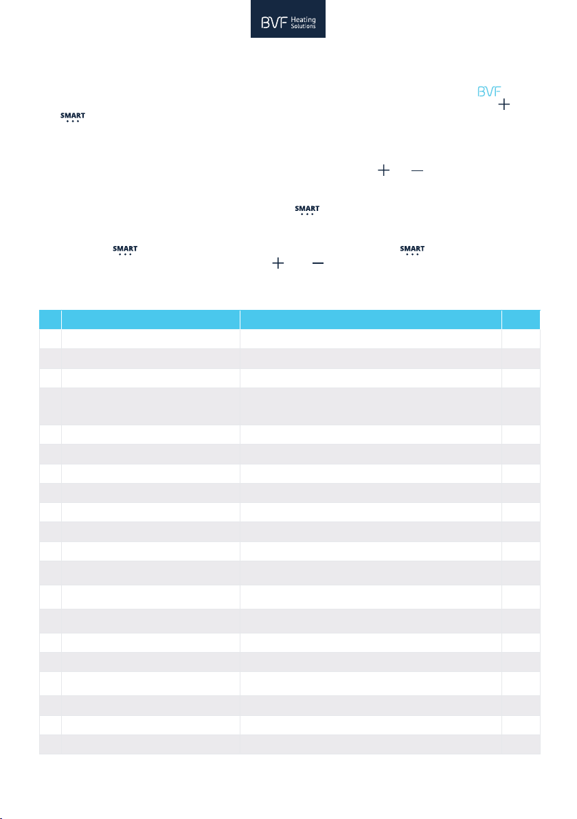
DEFAULT VALUES
Period Wake up 1 Leave Home 2 Return Home 3 Sleep 4
Time Temp. Time Temp. Time Temp. Time Temp.
1-5 (Mon.-Fri.) 7:00 22°C 8:30 19°C 17:00 22°C 22:00 19°C
6 (Sat.) 8:00 22°C 8:30 22°C 17:00 22°C 22:00 19°C
7 (Sun.) 8:00 22°C 8:30 22°C 17:00 22°C 22:00 19°C

10
8. FACTORY SETTINGS MENU POINTS
The factory-set values can be checked and, if needed, modied by entering the factory menu. To
enter the factory menu, rst turn the thermostat o. The display will only show the brand
letters in the upper right corner. Now touch and keep depressed at the same time the and
the buttons for at least 5 seconds. On entering the rst point of the factory menu will ap-
pear: by default the temperature numerical value shows 0.0°C and menu point 01 appears in the
right bottom corner of the display. This menu makes it possible to set the dierence between
the temperature shown by the thermostat and the real temperature of the room. You can set
the temperature dierence with the correct sign by touching the or button several times,
as needed. If, for instance, the thermostat, when turned on, shows 21.5°C and the real tempera-
ture of the room is 20.0°C, then you have to set a value of -1.5°C in menu point 01 of the factory
settings. For approval and proceeding touch the button once briey. Attention! Saving of
the settings will take place automatically even if no further steps follow and in about 15 seconds
the thermostat will turn o. In the factory menu (after entering it again or setting menu 01 by
touching the button) you can proceed always by touching the button briey, and in
the individual menu points you can use the or button for setting the values.
DEFAULT VALUES
Description Range Default
01 Temp. Oset -8°C ~ 8°C 0
02 Set Point Max. 5°C ~ 80°C 35°C
03 Set Point Min. 5°C ~ 80°C 5°C
04 Sensor Select
ROOM
SURFACE
Room + Surface
05 Frost Protection Temp. 5°C ~15°C 5°C
06 Surface Temp. Display Read Only
07 High Temp. Protection 10°C ~ 80°C 32°C
11 Reset rE(Yes)
12 Key lock 0 - o, 1 - on 0
13 Master ID address Read Only
14 OWD function ON/OFF Select 0 - o, 1 - on 0
15 OWD Detect Time Select 2 ~ 30 mins 15
mins
16 OWD Drop Temp. Select (within detect
time) 2 / 3 / 4°C 2°C
17 OWD Delay time select (Return to previous
working status) 10 ~ 60 mins 30
mins
18 The temp. di to exit high protection mode 1°C ~ 3°C 1°C
19 External sensor temp. oset -8°C ~ 8°C 0
20 Energy optimisation 1: electric radiator 3: ceiling heating
2: heating panel 4: oor heating 2
21 Brightness (Standby Mode) 0 - 100% 5%
22 Software version Read Only
23 Read Only

11
DETAILED DESCRIPTION OF THE MENU POINTS:
01 Calibration of the thermometer – a true-to-sign dierence between the value shown
by the thermostat and the real temperature of the room. If, for example, the thermostat,
when turned on, shows 21.5°C and the real temperature of the room is 20.0°C, then in
menu point 01 of the factory settings a value of -1.5°C should be set.
02 Maximum temperature – the maximum temperature value that can be set on the ther-
mostat. No heating temperature higher than this value can be set on the device. The fac-
tory value is 35°C, and it can be varied between 5 and 80°C. The value set here will be the
maximum of all the adjustable temperatures of the controller.
03 Minimum temperature – the minimum temperature value that can be set on the ther-
mostat. No heating temperature lower than this value can be set on the device.
04 Selection of sensor – you can set the thermometer sensor on the basis of which the ther-
mostat performs its control function.
When set to the ROOM value, the thermostat will use onty the room thermometer on its
control panel for measuring. This setting can be used in the case of controlling an infrapa-
nel or electric radiator.
When set to the SURFACE value, the thermostat will only measure and display the heating
surface’s (oor or ceiling) temperature. A setting that can be used in the case of comfort or
additional surface heating.
When set to the ROOM + SURFACE combined value, the thermostat will display the room’s
temperature and this can also be set, but the temperature of the heating surface (oor or
ceiling) is also considered and it does not allow heating to a value higher than that even in
the case when the room has not reached the desired temperature value. A setting recom-
mended for oor or ceiling heating operated as an independent mode of heating.
05 Anti-freezing (also in turned o condition) – in case of reaching the temperature set
here the thermostat will turn heating on even in the case when it is otherwise switched
o. This function can be used for antifreezing in the case of winterized holiday homes, or
rooms and (oce) buildings having been out of use for a longer period of time. The conditi-
on of using the antifreezing function is that the controller be electrically live (the icon
will appear in the right upper corner of the display even if the device is turned o).
06 Temperature of the external (surface) sensor – a menu point suitable for setting the
display of the temperature measured by the thermostat’s surface sensor. This menu point
is suitable only for checking and reading the value which can not be modied.
07 Overheating protection – a setting necessary in the case of a surface heating (underoor
or ceiling heating). The value set here will be the maximum temperature of the heating sur-
face. When set, for example, to 30°C, the underoor heating will switch o when the oor
reaches the 30°C temperature (even in the case when the room’s temperature has not yet
reached the desired value). With the surface cooling back by 2°C (based on the example,
at a temperature of 28°C), heating will switch on again if the room temperature makes it
necessary. The recommended setting values for underoor heating are between 29-31°C,
and for ceiling heating between 45-48°C.
08 Inactive
09 Inactive
10 Inactive
11 Resetting the factory values – resetting of the thermostat’s factory values and settings.
The factory values are contained in the table below.

12
12 Keyboard locking (child lock) – 0 – o; 1 – on. In the turned on condition a icon will
appear in the display’s right upper corner on the starting screen of the thermostat within
15 seconds after the last intervention (touching of a button) and at the same time the child
lock function will get activated and the device will not react upon touching any button.
The keyboard lock function can be suspended by touching the and buttons simul-
taneously and keeping them depressed for 5 seconds. In this way this function will only be
broken (with breaks not longer than 15 seconds in the case of a continuous intervention);
the keyboard lock can be resolved by setting point 12 of the factory menu to 0.
13 Inactive
14 Sensing of open window – 0 – o; 1 – on. When on, the open window function gets activa-
ted on the controller which means that upon a temperature drop occurring after a certain
period of time the thermostat, supposing ventilation, will temporarily turn heating o in
order to avoid unnecessary energy consumption. The delay in activating this function, the
extent of temperature drop and the timing of switching heating on again can be set in
menu points 15-16-17.
15 Period of sensing open window (switch-on delay) – this function will switch on when
the time set here has elapsed. For example, if the numerical value set in this menu is 15,
heating will be turned o when within this 15-minute period the temperature has dropped
with the specied temperature value.
16 Open window temperature drop (within sensing time) – sensing limit value of the tem-
perature drop. For instance, if the numerical value set in the menu is 2, then within the time
frame set in menu 15 heating will switch o upon a 2°C temperature drop.
17 Open window delay period (returning to normal mode of operation) – heating will be
switched on again after the time specied here. If the numerical value of the menu is 30, it
means that heating will be switched on again 30 minutes after the temperature drop has
stopped.
An example of how the open window function works: the set values are: menu point 14 (1);
menu point 15 (15); menu point 16 (2); menu point 17 (30). Based on the settings the open
window function is active; in case of a temperature drop of 2°C occurring within 15 minu-
tes the thermostat switches the heating o, and in 30 minutes after the temperature drop
has ceased heating will be switched on again.
18 Cooling back limit after overheating – a function that can be used with surface heating,
in which heating will switch on when the temperature dierence set here has been rea-
ched, having previously reached the surface’s maximum value. For example, if the maxi-
mum surface value (menu point 7) is 29°C, the value set in menu 18 is 2°C, then heating will
switch on again when the oor’s surface temperature has cooled back to 27°C.
19 Calibrating the external sensor – a function used with surface heating and based on the
signed dierence between the temperature measured by the surface sensor and the real
temperature of the surface. For example, if in menu point 06 the thermostat shows +28°C,
while the real temperature of the surface is 25°C, then menu point 19 should be set to -3°C.
20 Optimisation of energy consumption – 1: electric radiator. Set it to this value if the hea-
ting controlled by the thermostat is an independent convection-type electric heating pro-
vided with built-in temperature controller (radiator). 2: infrapanel. Set it to this value if the
heating controlled by the thermostat is an independent radiation heating provided with
built-in surface temperature controller (infrapanel). 3: ceiling heating. Set it to this value if
the heating controlled by the thermostat is an electric radiation ceiling surface heating. 4:
underoor heating. Set it to this value if the heating controlled by the thermostat is a low
surface temperature electric underoor heating.

13
21 Brightness (Standby Mode) – brightness of thermostat’s backlight in standby mode. Du-
ring setting of thermostat, the screen is illuminated on 100% brightness; the screen will
fade to the percentage value dened here. This value can be changed between 0-100%.
22 Software version – version number of the software (rmware) running on the thermostat.
It is a read-only value.
10. FAULT FINDING
Fault phenomena of thermostats and their possible solutions
1. The thermostat’s display is dark, it is not lit
a. Is there any change upon touching the thermostat’s turn-on button?
YES – The thermostat has turned on, there is nothing else to do.
NO – see next answer.
b. Is there a icon on the display?
YES – The child lock function is on. Turn o the child lock as described in the
instructions manual.
NO – see next answer.
c. Is the small circuit breaker of the heating circuit switched on?
NO – Switch it on.
YES – see next answer.
d. Is there any change after removing the thermostat’s front panel and trying to switch
it on again?
YES – The thermostat has switched on, the ribbon cable has pressed the front panel;
when replacing the front panel take care to insert the ribbon cable in the small gap on
the rear side.
NO – see next answer.
e. Is the front panel of the thermostat connected to the rear panel, i.e. is the ribbon
cable connected?
NO – Connect it.
YES – see next answer.
f. Is it possible to measure voltage on the phase input of the thermostat’s built-in
relay?
NO – The thermostat does not receive power. Have the power supply of the aected
electrical circuit, the small circuit breakers, junction boxes and wires tested by an
electrician.
YES – see next answer.
g. Is there any visible abnormal change, such as sooting, or signs of injury or damage to
certain components, on the thermostat’s relay or front panel?
NO – The thermostat needs to be further examined, so please, send it to our central
brand shop or order our on-site troubleshooting and repair service.
YES – The device has likely been hit by electrical overvoltage and it should partly or
entirely be replaced. The thermostat needs further examination, so please, send it to
our central brand shop or order our on-site troubleshooting and repair service.

14
2. The display is lit, but heating is not working.
a. Is it the real room temperature that can be seen on the display?
NO – The thermostate needs calibration. Calibrate the device according to the
description in the instructions manual.
YES – see next answer.
b. When the thermostat is turned on touch the button so that the set value
exceeds the room temperature. Is the heating icon appearing on the display in a few
seconds with a soft clicking sound?
YES – The thermostat switches on. If the system still does not heat, further settings
are needed. It can occur on certain types that the thermostat does not supply power
through output points (controller does not switch on heating). The reason behind this
is the so-called „open window” function which turns o the heating in the case of high
drop of temperature to save energy. After airing through windows the thermostat turns
on automatically. The other possible reason is the selection of heating mode, based on
this the thermostat can control electric radiator, infrared panel heater and celiling- or
oorheating. Depending on the heating mode setting, the thermostat will turn o the
heating for 0, 2 or 4 minutes, respectively, within 20 minute cycles.
NO – see next answer.
c. Does the thermostat control a surface heating system?
YES – Check the controller’s surface limit values as described in the instructions manual.
If necessary, the setting limit value can be increased. If the surface temperature shows
an unrealistic value, further examination is required. If there is a piece of furniture, a
carpet or other heat insulating material over the oor sensor of the thermostat, remove
it so that the aected surface can give o heat. If there is no such a reason, the sensor
might be damaged.
NO – The thermostat requires further examinations. Please, send it to our central brand
shop or order our on-site troubleshooting and repair service.
3. After switching on or increasing the temperature value the thermostat clicks, the
heating icon is visible, but there is still no heating.
a. Is the power of the heating circuit higher than 3 kW (13 A)?
YES – the circuit in question is supplemented with a power switching relay. Please, ask
your electrician to check the proper working of the power switching relay, or order our
on-site troubleshooting service.
NO – see next answer.
b. Are the heating power supply wires connected to the built-in relay of the thermostat?
NO – Ask your electrician to connect it or order our on-site troubleshooting service.
YES – see next answer.
c. Can you measure voltage on the thermostat’s switched output?
YES – The thermostat functions well, troubleshooting should be continued with further
tests on the heating side.
NO – The thermostat requires further examination, so please, send it to our central
brand shop or order our on-site troubleshooting and repair service.
Table of contents
Popular Thermostat manuals by other brands

OJ Electronics
OJ Electronics MTC-1991-UFH instructions

Smart temp
Smart temp 42-159 Installation and operation manual

Carrier
Carrier Performance TP-NHP installation instructions

Copeland
Copeland TSTAT TS4275 Series Installation and operating instructions

HYSEN
HYSEN HY02TP WIFI user manual

LVI
LVI MILO ROCK manual