manuals.online logo
Brands
  1. Home
  2. •
  3. Brands
  4. •
  5. Mars
  6. •
  7. Thermostat
  8. •
  9. Mars HEAT CONTROLLER IR Wireless Thermostat User manual

Mars HEAT CONTROLLER IR Wireless Thermostat User manual

Heat Controller • 1900 Wellworth Ave. • Jackson, MI 49203 • (517)787-2100 • www.heatcontroller.com
USER MANUAL
IR Wireless Thermostat
IR Wireless Thermostat - User Manual Heat Controller
1.Operation guidelines…………………………………………………1
2.Thermostat installation……………………………………………11
3.Thermostat dismounting instruction…………………………16
4.Battery replacement……………………………………………… 17
Heat Controller IR Wireless Thermostat - User Manual
1
1. Operation guidelines
This wireless thermostat is for PTAC unit control. The LCD
screen displays the operating status.
Fig. 1
There are 7 buttons on the wireless thermostat. After very first
power on, the LCD screen displays all characters and then enters
ready mode. Initial value of the thermostat real time is 0:00AM,
Monday. Press "ON/OFF" button to turn on the wireless thermostat,
it will enter the default operating mode: cool mode, auto fan speed,
set point 25℃ (77℉). By pressing mode button, thermostat
performs sequential switching "Cool→Fan→Heat→Cool". Under
OFF mode, only "ON/OFF and TIME and SET" buttons are available.
When the thermostat is turned on, all buttons are available. Set
point, operation mode, fan speed settings and timing functions are
displayed with related characters on LCD screen. The details are
as follows:
SET Button
TIME Button
MODE Button
Fan Speed Button
ON/OFF Button
Decreasing Button
Increasing Button
LCD
Sending Window
LCD
IR Wireless Thermostat - User Manual Heat Controller
2
Fig.2
(1) Temperature display: displays room temperature ("Room"
character appears) or set point ("Set" character appears).The
set point range is 16℃–32℃ or 61℉–90℉.
(2) Fan speed display: displays Fan High, Fan Low, Fan
Auto.
(3)Mode display: displays Heat Mode, Cool Mode, Fan Mode.
(4)Timing display: displays 1–12H.
(5)Day display: displays Monday - Sunday.
(6)System time display: displays real time clock.
(7)Signal sending mark display: is displayed when a control
Timing Day System time Data sending mark
Mode temperature Fan speed
Heat Controller IR Wireless Thermostat - User Manual
3
signal is sent out.
(8)Locking display: When this mark appears, the thermostat is
locked, this time only ON/OFF button is available.
(9)Battery condition display: In case this mark appears,
control signal sending will become unavailable and you
need to replace batteries.
Function overview
(1) ON/OFF Button ( )
①Wireless thermostat shall perform sequential switching in the
order of "ON→OFF→ON" by each press of this button.
②If it is OFF→ON at the very first power on, the default setting is
set point 25℃(77℉), cool mode, auto fan, no timing.
③If it is OFF→ON not at the very first power on, all settings are
the same with the last settings. If any power off, timing function
will be cancelled.
④The ON/OFF button also acts as "ENTER" function during time
and menu settings. When these two settings are finished,
press ON/OFF to save and exit.
(2) MODE Button ( )
①Wireless thermostat performs sequential switching:
"Cool→Fan→Heat→Cool" by each press of MODE
button.
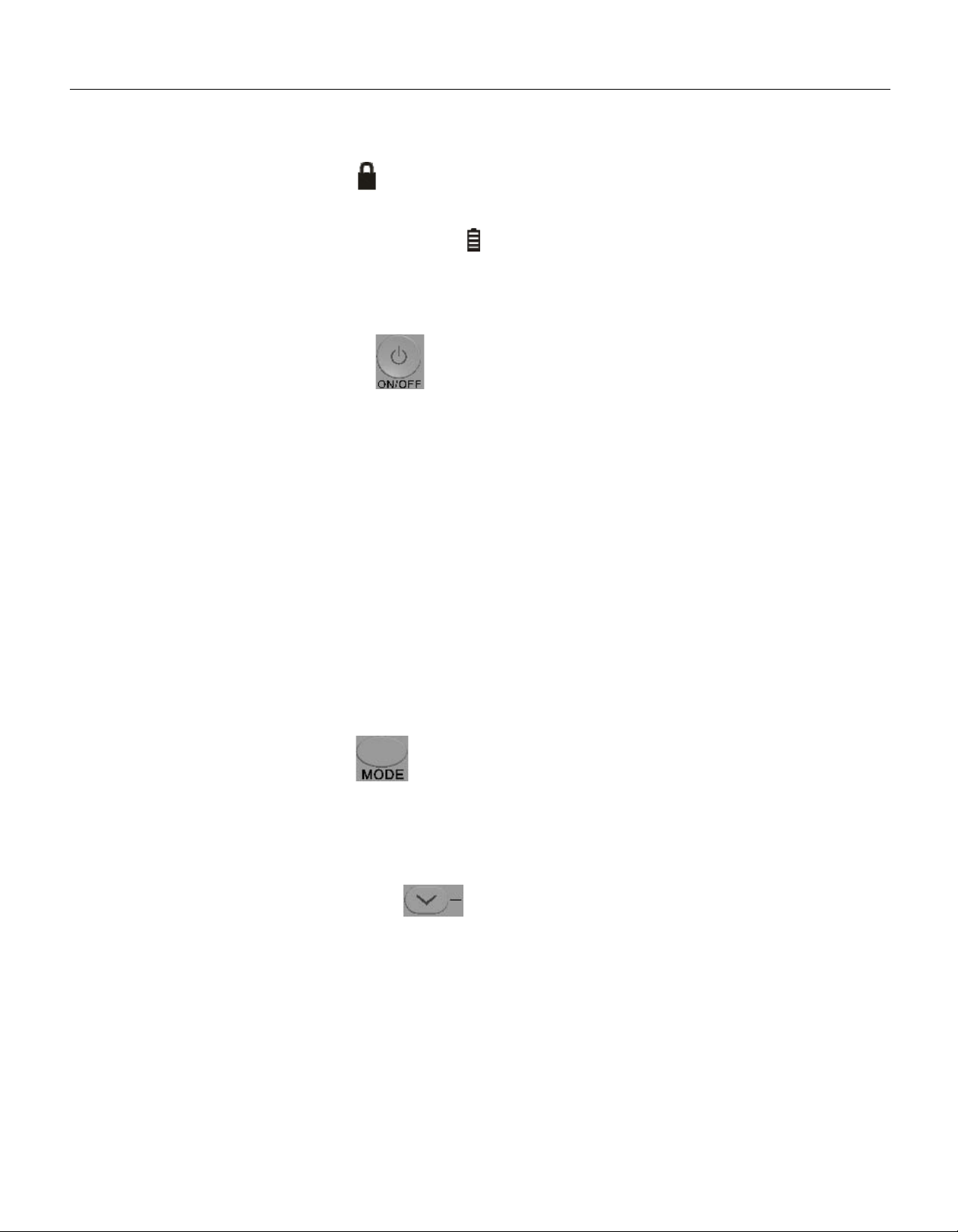
(3) Decreasing Button ( )
①Set point setting: the set point shall decrease by one degree for
each press of this button. The set point shall be lowered in the
order of "32℃→…→17℃→16℃", or " 90℉→…→62℉→61℉".
Decrease Button
IR Wireless Thermostat - User Manual Heat Controller
4
When the set point reaches 16℃ or 60℉, it will no longer do
anything by pressing this button.
②For system real time and day settings (the real time or day will
be flashing for prompt). Press this button to decrease time or
day.
③Menu setting: press this button to select parameter.
④Continuous change is realized by pressing and holding of this
button.
(4) Increasing Button ( )
①Set point setting: the set point shall increase by one degree for
each press of this button. The set point shall be higher in the
order of "16℃→17℃→…→32℃" or "61℉→62℉→…→90℉".
When the set point reaches 32℃ or 90℉, it will no longer do
anything by pressing this button.
②For system real time and day settings (the real time or day will
be flashing for prompt). Press this button to increase time or
day.
③Menu setting: press this button to select parameter.
④Continuous change is realized by a press and hold of this
button.
(5) Fan Speed Button ( )
①At the very first power on, the default fan speed is auto fan
speed.
②Under other modes, it shall perform sequential switching in the
order of "Fan Auto → Fan High →Fan Low → Fan Auto".
(6) TIME Button ( )
①
Set timer in 1–12H by pressing TIME button momentarily.
Increase Button
Heat Controller IR Wireless Thermostat - User Manual
5
"Turn off" unit time is set after thermostat is turned on and
"turn on" unit time is set after thermostat is turned off.
②Press and hold the TIME button for 5s to set system real time
clock and Day. When minute is flashing, you can now set
minute by or button.
③After finishing minute setting, press TIME button again and
hour will be flashing. You can now set hour by or
button.
④After finishing hour setting, press TIME button again and Day
will be flashing. You can now set day by or
button.
⑤After setting, 5 seconds later thermostat will save it
automatically.
(7) Setting Button ( )
①Press and hold the SET button for 5s to enter menu setting, C1
will display as shown in Fig.3 & Fig.4. This time, you can select
the temperature scale by pressing the decreasing or
increasing button.
Fig.3 C1(displays in Fahrenheit)
IR Wireless Thermostat - User Manual Heat Controller
②Momentarily press the SET button to skip to next setting. The
menu sequence is: C1→C2→C3→C4→C5→C6→C7→C8→C1.
Interfaces of C2–C8 are as below:
!
Warning:
!
Notice:
The mark indicates that any improper operation
may cause casualties or severe injury.
The mark indicates that any improper operation
may cause personnel injury or property damage.
Fig.5 C2(auto sending cycle, unit in minute)
Fig.4 C1(displays in Celsius)
6
Heat Controller IR Wireless Thermostat - User Manual
Fig.7 C4(buttons are unlocked)
Fig.8 C4(buttons except ON/OFF are locked)
Fig.6 C3(brightness of backlight)
7
IR Wireless Thermostat - User Manual Heat Controller
Fig.11 C6(temperature calibration)
Fig.10 C5(displays room temperature)
Fig.9 C5(displays set point)
8
Heat Controller IR Wireless Thermostat - User Manual
③For about 5s after setting is completed, parameter will be
saved automatically and it exits the setting interface. Pressing
ON/OFF button will save parameters and exit the setting
immediately.
Fig.13 C8(minimum set point for cooling)
Fig.12 C7(maximum set point for heating)
9
IR Wireless Thermostat - User Manual Heat Controller
Menu NO. Definition Description
C1 temperature
scale
Fahrenheit(℉)
(default) Temperature scale is Fahrenheit.
Celsius(℃) Temperature scale is Celsius.
C2
Control signal
auto sending
cycle
1– 20 minutes
(default: 15)
Automatically send out the last
control signal every 15 minutes
(default).
C3 Back light
brightness 0 – 10 (default 3) LCD screen back light brightness
grade.
C4 Button Lock
0 (default) All buttons are free.
1 Only ON/OFF button is available,
Other buttons are locked.
C5 Temperature
display
Set (default) Displays set point
Room Displays room temperature
C6 Temperature
calibration
-9—9℉/-9—9℃
(default: 0)
If you find the room temperature
display has some bias, you can
calibrate it here.
If temperature scale is changed,
you should calibrate it again.
C7 Maximum set
point for heating
61-90℉/ 16-3 2℃
(default:
90℉/32℃)
If the set point is higher than the
maximum heating temperature
during setting process, the set
point is limited to the maximum
heating temperature.
C8 Minimum set
point for cooling
61-90℉/ 16-3 2℃
(default:
60℉/16℃)
If the set point is lower than the
minimum cooling temperature
during setting process, the set
point is limited to the minimum
cooling temperature.
10
Heat Controller IR Wireless Thermostat - User Manual
Note: In order to extend batteries' life, when the control effect is not
negatively affected, it is suggested to set C2 (automatic control
signal sending cycle) as 20 minutes. (The wireless thermostat
will send the latest control signal to PTAC unit many times
automatically in order to make sure the receiver has
successfully received the command. If someone stands in front
of the sending window, the IR signal may fail to be received, so
the design initiates signal sending more than once. The more
frequent the sending, the more the power consumption will be.)
2. Thermostat installation
Safety notice
■ Installation location shall be far away from high temperature or
direct sunlight. Otherwise, the wireless thermostat life would be
shortened. It may also cause battery leakage contamination or
explosion under high temperature!
■ Please read the safety notice carefully before installation.
■ Safety notice described below must be observed.
■ Meaning of various parts:
■ After installation process is completed, please confirm
there is no abnormal phenomenon in trial run. The
instruction manual shall be handed to customer for
storage.
!
Warning:
!
Notice:
The mark indicates that any improper operation
may cause casualties or severe injury.
The mark indicates that any improper operation
may cause personnel injury or property damage.
11
IR Wireless Thermostat - User Manual Heat Controller
12
Icon description
Icon
!
!
Warning
Entrusted for
installation
Use
warning Prohibition
name
Indicates prohibition. Specific content prohibited is
expressed with a figure or letter in or around icon.
Indicates compulsory. Specific compulsory content is
expressed with a figure or letter in or around icon.
Please entrust a dealer or professional
for installation. Installation
personnel must possess related
professional knowledge. Any
inaccurate operation in unauthorized
installation shall result in fire, electric
shock or injury.
o operation by wet hand is permitted.
No water is permitted in wireless
thermostat, otherwise, it may be
damaged.
Prohibition
It is prohibited to spray flammable
agent directly to wireless thermostat.
Otherwise, it may cause fire.
Warning:
!
·A dealer or professional personnel shall be entrusted for
installation. Imperfect installation done by other
personnel may result in electric shock or fire.
·Please observe the instruction manual strictly. Improper
installation may cause electric shock or fire.
·Installation shall be done by a professional person. Any
improper installation may cause electric shock or fire.
·No random dismounting or installation is permitted.
Random dismounting or installation may cause
abnormal operation of wireless thermostat . It may result
in trouble as well.
Do not operate with wet hands. No water is
permitted in wireless thermostat. It may be
damaged.
Please strictly observe the instruction manual. Improper
installation may cause electric shock or re.
Heat Controller IR Wireless Thermostat - User Manual
The specific installation steps of the wireless thermostat are as
shown in Fig.14.
(a) (b)
(c) (d)
(e) (f)
Fig.14
Screw(ST3.9×20–C)
13
IR Wireless Thermostat - User Manual Heat Controller
Fig.15
Note: Excessive tightness of screw may result in distortion of
back cover.
Installation location
(1).Structure of the senders
In order to meet installation requirements, the 3 senders on
the thermostat are fixed in different directions, in order to
widen the signal sending angle. Figure 16a&b shows the
details.
Fig.16a. Sending window Fig.16b. Structure of senders
30° 30°
14
Heat Controller IR Wireless Thermostat - User Manual
(2).Choose location
In order to ensure better control, there are 3 suggested
installation locations for the wireless thermostat. For details,
refer to Fig.17.
①. Face right ahead of the receiving window on the PTAC unit
(location A).
②. At the left side of 30° angle to the receiving window
(location B).
③. At the right side of 30° angle to the receiving window
(location C).
Fig.17. Suggested installation locations.
There should not be obstacles at the dash line to block the control
signal.
Thermostat
Thermostat
Thermostat
PTAC
ROOM
30°
30°
Sending window
Receiving window
C
A
B
15
IR Wireless Thermostat - User Manual Heat Controller
NOTE: During battery installation, in order to prevent wireless
thermostat from being burnt, please guarantee that positive
and negative pole of battery are consistent with positive and
negative pole icon on the front cover.
3. Thermostat dismounting instruction
If wireless thermostat should be disassembled for replacement of
new battery or other conditions, please follow the operation steps
below:
(1).As shown in Fig.18, use slot type screwdriver to clip card slot
below the wireless thermostat to pry front cover downwards
and open the wireless thermostat. During the whole process,
please pay attention to the prying direction so as to avoid part
damage.
(2).After step (1) is completed, wireless thermostat can be opened
by moving front cover part along the direction of arrow, as
Fig.19 shows.
Fig.18
Back cover
Front cover
Binding position
Slot type
screwdriver
Position Ⅰ
Position Ⅱ
16
Heat Controller IR Wireless Thermostat - User Manual
Fig.19
4. Battery replacement
(1). When low battery prompt sign appears on the screen,
please replace the 4 batteries with the same specification.
(2). Improper use of batteries of other types than originally
supplied may damage wireless thermostat! The whole set (4 in
total) of batteries must be replaced for each replacement. It is
prohibited to replace only a portion and mix new and old
batteries together! Otherwise, new battery life will be
shortened and practical use is affected!
(3). In order to prevent system time from being lost during
replacement process and causing resetting trouble, you
should finish the job within 10s or so. If you fail to do so and
system time is lost, you should set the time again.
Front cover
Rear cover
17
:HOOZRUWK$YH-DFNVRQ0,3KZZZKHDWFRQWUROOHUFRP


'XHWRRQJRLQJSURGXFWLPSURYHPHQWVVSHFLILFDWLRQVDQGGLPHQVLRQVDUH
VXEMHFWWRFKDQJHDQGFRUUHFWLRQZLWKRXWQRWLFHRULQFXUULQJREOLJDWLRQV'HWHUPLQLQJWKH
DSSOLFDWLRQDQGVXLWDELOLW\IRUXVHRIDQ\SURGXFWLVWKHUHVSRQVLELOLW\RIWKHLQVWDOOHU
$GGLWLRQDOO\WKHLQVWDOOHULVUHVSRQVLEOHIRUYHULI\LQJGLPHQVLRQDOGDWDRQWKHDFWXDOSURGXFW
SULRUWREHJLQQLQJDQ\LQVWDOODWLRQSUHSDUDWLRQV
,QFHQWLYHDQGUHEDWHSURJUDPVKDYHSUHFLVHUHTXLUHPHQWVDVWRSURGXFWSHUIRUPDQFH
DQGFHUWLILFDWLRQ$OOSURGXFWVPHHWDSSOLFDEOHUHJXODWLRQVLQHIIHFWRQGDWHRIPDQXIDFWXUH
KRZHYHUFHUWLILFDWLRQVDUHQRWQHFHVVDULO\JUDQWHGIRUWKHOLIHRIDSURGXFW
7KHUHIRUHLWLVWKHUHVSRQVLELOLW\RIWKHDSSOLFDQWWRGHWHUPLQHZKHWKHUDVSHFLILF
PRGHOTXDOLILHVIRUWKHVHLQFHQWLYHUHEDWHSURJUDPV
5/2015

Other Mars Thermostat manuals

Mars 70814 User manual

Mars

Mars 70814 User manual

Mars 70801 User manual

Mars

Mars 70801 User manual

Mars 70812 User manual

Mars

Mars 70812 User manual

Mars 70813 User manual

Mars

Mars 70813 User manual

Mars 70802 User manual

Mars

Mars 70802 User manual

Mars 70803 User manual

Mars

Mars 70803 User manual

Mars 70810 User manual

Mars

Mars 70810 User manual

Popular Thermostat manuals by other brands

Rotex RKRTR installation manual

Rotex

Rotex RKRTR installation manual

Excel TH-2005 E-Series user guide

Excel

Excel TH-2005 E-Series user guide

Vaillant VRT 392 OPERATING AND INSTALLATION Manual

Vaillant

Vaillant VRT 392 OPERATING AND INSTALLATION Manual

Energate FZ100C installation guide

Energate

Energate FZ100C installation guide

Peco WAVE WIRELESS TW205-206 installation instructions

Peco

Peco WAVE WIRELESS TW205-206 installation instructions

Hive Active Heating user guide

Hive

Hive Active Heating user guide

John Guest JGSTAT1 instruction manual

John Guest

John Guest JGSTAT1 instruction manual

Warmup UDG instructions

Warmup

Warmup UDG instructions

Braeburn 2010 user manual

Braeburn

Braeburn 2010 user manual

Danfoss TP5000 si range Installation and user instructions

Danfoss

Danfoss TP5000 si range Installation and user instructions

Bsmarthome SH-01 Series installation guide

Bsmarthome

Bsmarthome SH-01 Series installation guide

OJ Electronics PISTESARJAT Microtemp MCD5 manual

OJ Electronics

OJ Electronics PISTESARJAT Microtemp MCD5 manual

Honeywell SUITEPRO TB6575 installation instructions

Honeywell

Honeywell SUITEPRO TB6575 installation instructions

SWITCHEE Smart Thermosat Programming guide

SWITCHEE

SWITCHEE Smart Thermosat Programming guide

Systems Controls & Instruments ERV-24-Super Quick start and wiring instruction for installers

Systems Controls & Instruments

Systems Controls & Instruments ERV-24-Super Quick start and wiring instruction for installers

White Rodgers 1F78 installation instructions

White Rodgers

White Rodgers 1F78 installation instructions

Perry 1TXCRTX05 manual

Perry

Perry 1TXCRTX05 manual

HEVAC RTC4v manual

HEVAC

HEVAC RTC4v manual

manuals.online logo
manuals.online logoBrands
  • About & Mission
  • Contact us
  • Privacy Policy
  • Terms and Conditions

Copyright 2025 Manuals.Online. All Rights Reserved.