5
“ARVA” - AUTOMATIC RAIL VOLTAGE ADJUSTMENT CIRCUITRY:
Cadence United Series amplifiers feature “ARVA” circuitry in their power supply. This circuit constantly
monitors the output stage and under high current demands will adjust the power supply rail voltages
so that enough power is available for peak situations.The “ARVA” also improves the damping factor of
the amplifier when playing low impedance mono loads. Cadence United Series amplifiers have tighter
sounding bass reproduction thanks to
this unique circuitry.
BATTERY VOLTAGE:
Cadence United Series amplifiers are rated and regulated to 13.8 volts and below. Increasing voltage to
14.4 volts will increase the power output of the amplifier in the same proportion. Maximum input voltage
is14.4volts whilethe minimumvoltageis12volts.
*** DO NOT EXCEED 14.4 INPUT VOLTAGE. ***
Though capable of high power reproduction, Cadence United Series amplifiers are not competition style
amplifiers! They were designed for audiophile sound reproduction.
PROTECTION CIRCUITRY:
Cadenceamplifiers incorporate many outstanding protection circuits tohelp protect the amplifier from
being damaged duringoperating conditions.
Thermal Protection: When the amplifier reaches an unsafe operating temperature of 80 degrees Celsius
the amplifier will turn off. Once the amplifier cools down, simply reset the amplifier by its Remote
connection, (turn the amplifier off and then on again once you have given the amplifier a chance to cool
down) and the amp will once again begin to play.
If you live in a hot climate we suggest installing additional cooling fans in your trunk
to exhaust the hot air which can build up in the trunk this will help keep the ambient
temperature in the trunk as low as possible so that your amps work awlessly and without any
musical interruption.
Speaker Short Circuit Protection: Should your speakers short circuit due to voice coil burn out, or should the
amplifier sense an impedance too low to handle, the Protection LED will light, indicating a diagnostic condition.
Turn off your system, disconnect one speaker at a time and try to determine which speaker might be faulty.
Correct the condition and restart the amplifier.You must reset the amplifier by turning it OFF and then ON again
by the Remote power connection after correcting a diagnostic condition. (Turn your radiooff and then on again.)
Clipping or total shutdown may also be a result of a bad ground connection or loose
ground. If you nd that your speakers and speaker wires are not shorted, please check
your ground connection.
Input Overload Protection: This circuit will either shutdown the amplier completely or
make the amplier spurt on and o indicating that it is in a diagnostic condition. Turn the
system o and reduce the gain on the amplier or volume from your head unit, this should
result in a corrected condition.
DC Oset Protection: Should any DC voltage try to enter the amplier via the speaker
terminals it will cause the amplier to shut down and not operate until this condition
is remedied. This circuit will also protect damaging high DC voltages from reaching your
speakers should your amplier ever malfunction.
INSTALLATION BASICS:
Before you begin with your installation, disconnect the NEGATIVE (-) terminal from your car’s
battery. This safety precaution will avoid possible short circuits while wiring your amplier.
Cadence ampliers operate on 12-volt negative ground systems only.
It is recommend that you layout your sound system design on paper rst. This will help
you during the installation so that you will have a wiring ow chart and not miss-wire any
of your components.
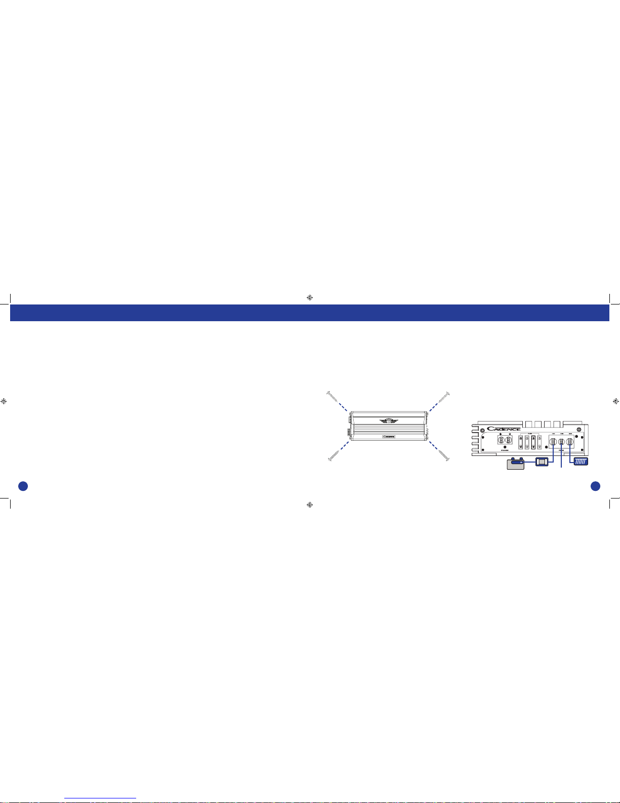
Mount the amplier in the trunk or hatch area of your vehicle. Never install an amplier in
the engine compartment or on the rewall. Please be sure to leave breathing room around
the amplier heat sink so that it can dissipate the heat it produces eciently. The amplier
can be installed either horizontally or vertically.
When mounting the amplier on the trunk oor, be sure to watch for your gas tank, gas
lines and electrical lines. Do not drill or mount any screws where they might penetrate the
gas tank of your car.
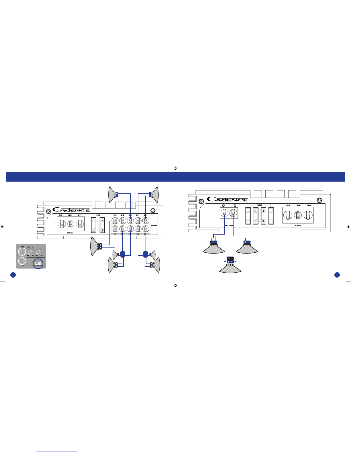
SETTING THE CONTROLS:
AUDIO PREAMP INPUT
The United Series ampliers feature RCA pre amp inputs. Run RCA cables from your sound
source to the inputs of the amplier. We suggest the use of high quality shielded RCA patch
cords to help reduce and eliminate unwanted electrical noise to your system.
Be sure to run the RCA cables on the opposite side of the vehicle that you used to carry the
power and ground leads of the amplier.
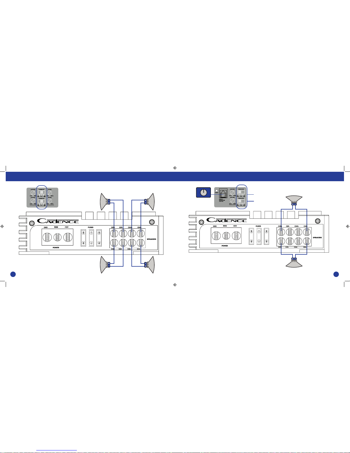
USING THE BUILT-IN LOW PASS ELECTRONIC CROSSOVER
All the United Series ampliers feature 12dB per octave fully adjustable low-pass and high
pass electronic crossovers.
For Low Pass sub woofer systems, set the CROSSOVER MODE switch to LOW PASS. Now the
knob marked FREQUENCY will control the low pass frequencies depending on the model
anywhere from 40Hz to 150Hz. A frequent error made is setting the low pass frequency
too low, especially when using vented sub woofer enclosures. We recommend that for
most installations you do not set the frequency knob lower than 80 - 100Hz (the 12 o’clock
position).
When using the ampliers for component speakers or co-axials, you will want to set the
CROSSOVER MODE switch to HIGH PASS. The FREQUENCY control knob adjusts the high
pass frequencies between 50Hz and 500Hz. Do not attach tweeters directly to the amplier,
(even in the high pass mode) without a secondary passive crossover to protect them. 500Hz
high pass is not a frequency high enough for tweeters.
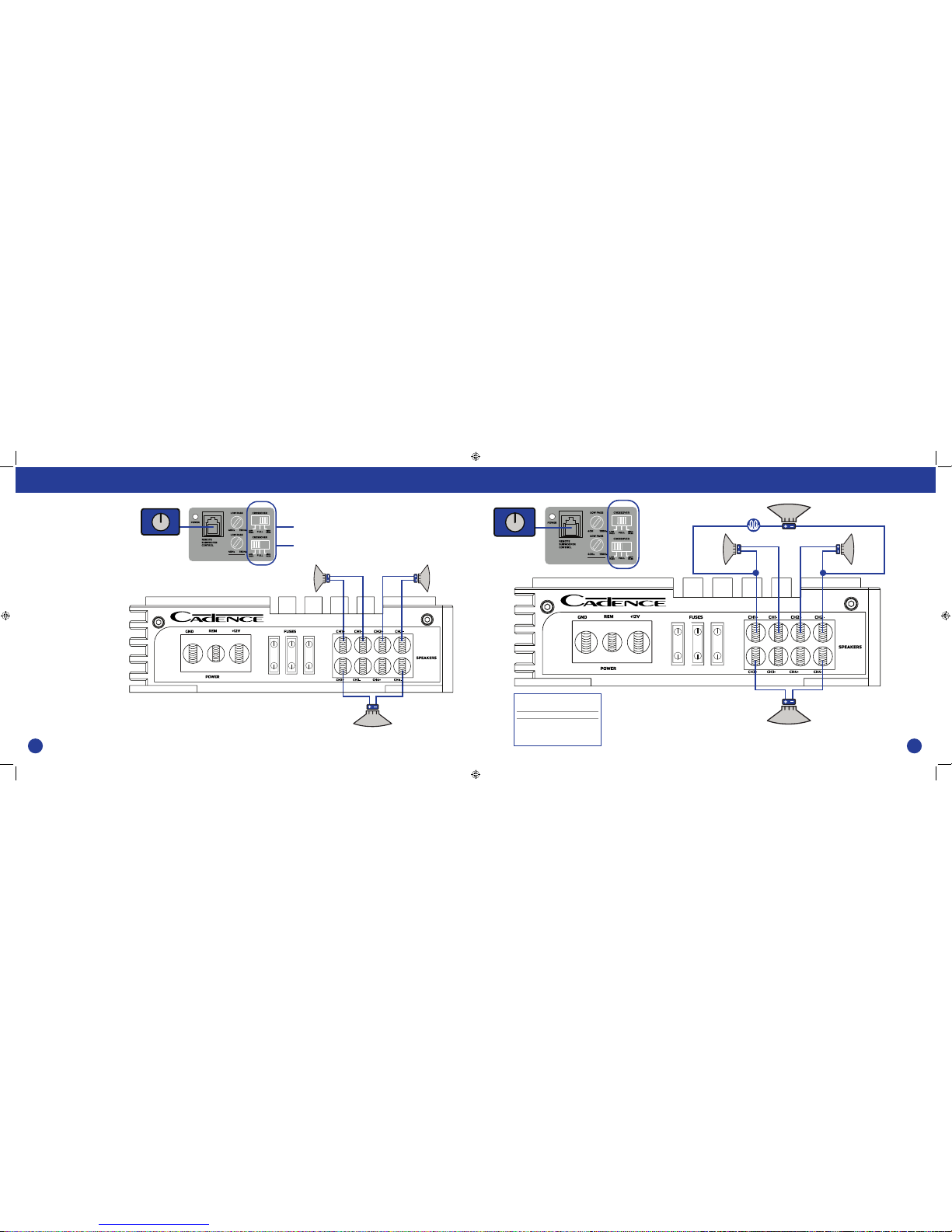
SUBSONIC FILTERING
For sub woofer installations with a passive LP crossover, you can set the amplier’s
CROSSOVER MODE selector to HIGH PASS while setting the FREQUENCY KNOB to 30Hz, this
will act as SUBSONIC FILTER for all signals below 30Hz. This is especially useful for vented
enclosures where the port tuning frequency falls below the sub woofer tuning frequency to
protect against sub woofer unloading.
REMOTETURN ON CONNECTION:
The remote turn on connection is located on the barrier strip next to the power and ground
connections.This connection is responsible for turning the amplier on and o with the rest of the
system. A smaller gauge wire can be used to make this connection to your radio’s power antenna
lead. Should your system not have any turn on leads, you can wire the remote terminal to an
accessory lead, which turns on, withyour cars ignition.
POWER/GROUND WIRING:
The United Series ampliers are supplied with built-in fuses, never replace the fuse that the amp
came with, with one of a larger value.
We suggest you construct a Red wiring harness with 2 additional fuses. One fuse should be located
near the car battery.This fuse near the battery oers protection against damage from short circuits
to the car chassis between the battery and the amplier. A second fuse closer to the amplier oers
additionalsafetytotheamplieritself. This fusedredpower wire shouldbeattachedto theamplier
power terminal marked 12V+.
The wire harness should be made of red primary cable of at least 8 gauge for the F200-2 and at
least 4 gauge for all other larger models. The harness should terminate in a large ring terminal for
connection directly to the positive terminal of the car battery. Use a spade plug to attach the wire,
which connects to the amplier location marked 12V+.
Asecondblack colorwireofequalgauge shouldbeusedas a groundconnection toa weldedchassis
member. When connecting the ground wire make sure that there is no paint or other insulator
blocking a good ground connection. When installing multiple ampliers, mount them in close
proximity so that they can all share the same ground point. Attach the black ground wire to the
amplier screw terminal marked Ground.
We recommend that you use the Cadence AMPKIT4 or AMPKIT8 amplier installation kits, which
contains all the cabling and accessories necessary for a good, reliable installation.
Over the years we have received ampliers back to our service department with melted power/
groundterminals. Thecause of thisisa badgroundconnection.When thereisa lackofgood ground,
heatbuildsupattheweakest pointwhichhappenstobethecontactscrewoftheamplier terminal.
Over time the heat generated will begin to melt the terminal. It is a good practice to feel the power
and ground wireswith your hands, near their amplier connection after having played the amp for
a while. If the wires feel hot to the touch you probably have a bad or loose connec tion. If you are sure
of your connections and the wires still feel hot to the touch, you should upgrade the gauge of wire
to next heaviest gauge.
Features Installation Basics