CADnetwork Workstation W30 User manual

Workstation W30
1-1
Chapter 1
Product Introduction
1.1 Motherboard overview
1.1.1 Before you proceed
Take note of the following precautions before you install motherboard components or change
any motherboard settings.
• Unplugthepowercordfromthewallsocketbeforetouchinganycomponent.
• Beforehandlingcomponents,useagroundedwriststraportouchasafelygrounded
objectorametalobject,suchasthepowersupplycase,toavoiddamagingthemdue
to static electricity.
• HoldcomponentsbytheedgestoavoidtouchingtheICsonthem.
• Wheneveryouuninstallanycomponent,placeitonagroundedantistaticpadorinthe
bag that came with the component.
• Beforeyouinstallorremoveanycomponent,ensurethattheATXpowersupplyis
switched off or the power cord is detached from the power supply. Failure to do so
maycauseseveredamagetothemotherboard,peripherals,orcomponents.
Chapter 1: Product Introduction

1-2 Chapter 1: Product Introduction
Chapter 1
Refer to 1.1.9 Internal connectors and 2.3.1 Rear I/O connection for more information
about rear panel connectors and internal connectors.
1.1.2 Motherboard layout

Workstation W30
1-3
Chapter 1
Layout contents
Connectors/Jumpers/Buttons and switches/Slots Page
1. DDR4DIMMslots 1-5
2. CPU,CPUoptional,extension,andchassisfanconnectors(4-pin
CPU_FAN;4-pinCPU_OPT;4-pinW_PUMP;4-pinH_AMP_FAN;5-pin
EXT_FAN,4-pinCHA_FAN1-2)
1-25
3. LGA2011-3CPUsocket 1-4
4. ATXpowerconnectors(24-pinEATXPWR;8-pinEATX12V_1;4-pin
EZTX12V_2)
1-26
5. MemOK!button 1-10
6. Intel®X99SerialATA6Gb/sconnectors(7-pinSATA6G_12,SATA6G_34,
SATA6G_56/SATAEXPRESS,SATA6G_78,SATA6G_910)
1-21
7. USB3.0connectors(20-1pinUSB3_12,USB3_34) 1-23
8. CPUOverVoltagejumper(3-pinCPU_OV) 1-13
9. U.2connector(U.2) 1-33
10. EZXMPswitch 1-11
11. Thunderboltheader(5-pinTB_HEADER) 1-29
12. ClearRTCRAMjumper(2-pinCLRTC) 1-12
13. Systempanelconnector(20-8pinPANEL) 1-27
14. DirectKeyconnector(2-pinDRCT) 1-28
15. USB2.0connectors(10-1pinUSB1112;USB1314) 1-24
16. T_Sensorconnector(2-pinT_SENSOR1) 1-29
17. M.2socket3 1-22
18. TPMconnector(14-1pinTPM) 1-28
19. Q-CodeLEDs 1-15
20. Resetbutton 1-9
21. Power-onbutton 1-9
22. AuraStripHeaders(4-pinRGB_HEADER) 1-32
23. Serialportconnector(10-1pinCOM) 1-30
24. Frontpanelaudioconnector(10-1pinAAFP) 1-31
25. Digitalaudioconnector(4-1pinSPDIF_OUT) 1-22

1-4 Chapter 1: Product Introduction
Chapter 1
1.1.3 Central Processing Unit (CPU)
ThemotherboardcomeswithasurfacemountLGA2011-3socketdesignedforIntel®Core™
i7processors.
• EnsurethatallpowercablesareunpluggedbeforeinstallingtheCPU.
• Uponpurchaseofthemotherboard,ensurethatthePnPcapisonthesocketandthe
socketcontactsarenotbent.ContactyourretailerimmediatelyifthePnPcap
ismissing,orifyouseeanydamagetothePnPcap/socketcontacts/motherboard
components.willshoulderthecostofrepaironlyifthedamageisshipment/transit-
related.
• Keepthecapafterinstallingthemotherboard.willprocessReturnMerchandise
Authorization(RMA)requestsonlyifthemotherboardcomeswiththecaponthe
LGA2011-3socket.
• Theproductwarrantydoesnotcoverdamagetothesocketcontactsresultingfrom
incorrectCPUinstallation/removal,ormisplacement/loss/incorrectremovalofthePnP
cap.

Workstation W30
1-5
Chapter 1
Recommended memory congurations
1.1.4 System memory
Themotherboardcomeswitheight(8)DDR4(DoubleDataRate4)QuadInlineMemory
Modules(DIMM)slots.
ADDR4moduleisnotcheddifferentlyfromaDDR,DDR2,orDDR3module.DONOT
installaDDR,DDR2,orDDR3memorymoduletotheDDR4slot.

1-6 Chapter 1: Product Introduction
Chapter 1
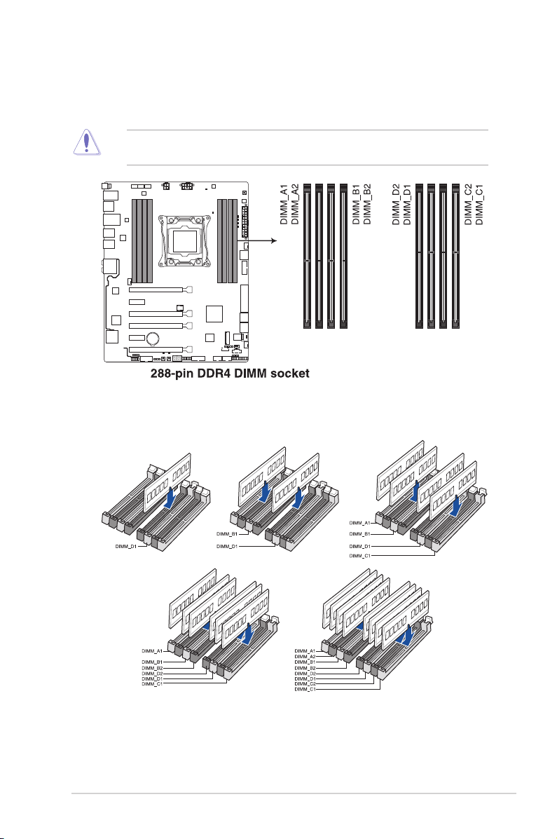
• YoumayinstallvaryingmemorysizesinChannelA,ChannelB,ChannelC,and
ChannelD.Thesystemmapsthetotalsizeofthelower-sizedchannelforthedual-
channelconguration.Anyexcessmemoryfromthehigher-sizedchannelisthen
mapped for single-channel operation.
• AccordingtoIntel®CPUspec,DIMMvoltagebelow1.65Visrecommendedtoprotect
theCPU.
• Duetothememoryaddresslimitationon32-bitWindows®OS,whenyouinstall4GB
ormorememoryonthemotherboard,theactualusablememoryfortheOScanbe
about3GBorless.Foreffectiveuseofmemory,werecommendthatyoudoanyofthe
following:
a) Useamaximumof3GBsystemmemoryifyouareusinga32-bitWindows®OS.
b) Installa64-bitWindows®OSwhenyouwanttoinstall4GBormoreonthe
motherboard.
c) Formoredetails,refertotheMicrosoft®support site at http://support.microsoft.
com/kb/929605/en-us.
• ThedefaultmemoryoperationfrequencyisdependentonitsSerialPresenceDetect
(SPD),whichisthestandardwayofaccessinginformationfromamemorymodule.
Underthedefaultstate,somememorymodulesforoverclockingmayoperateata
lowerfrequencythanthevendor-markedvalue.Tooperateatthevendor-marked
oratahigherfrequency,refertosection3.5 Ai Tweaker menu for manual memory
frequencyadjustment.
• Forsystemstability,useamoreefcientmemorycoolingsystemtosupportafull
memoryload(8DIMMs)oroverclockingcondition.
• AlwaysinstalltheDIMMSwiththesameCASLatency.Foranoptimumcompatibility,
werecommendthatyouinstallmemorymodulesofthesameversionordatacode
(D/C)fromthesamevendor.Checkwiththevendortogetthecorrectmemory
modules.
• ThedesignoftheDIMMfanmayvary.EnsurethattheDIMMfantstothe
motherboard.
Memory congurations
Youmayinstall2GB,4GBand8GBunbufferedandnon-ECCDDR4DIMMsintotheDIMM
sockets.

Workstation W30
1-7
Chapter 1
1.1.5 Expansion slots
Unplugthepowercordbeforeaddingorremovingexpansioncards.Failuretodosomay
cause you physical injury and damage motherboard components.
Slot No. Slot Description
40-LANE 28-LANE
1PCIe3.0/2.0x16_1slot PCIe3.0/2.0x16_1slot
2PCIe2.0x1_1slot PCIe2.0x1_1slot
3PCIe2.0x16_2slot PCIe2.0x16_2slot
4PCIe3.0/2.0x16_3slot PCIe3.0/2.0x16_3slot
5PCIe2.0x1_2slot PCIe2.0x1_2slot
6PCIe3.0/2.0x16_4slot PCIe3.0/2.0x16_4slot

1-8 Chapter 1: Product Introduction
Chapter 1
• WerecommendthatyouprovidesufcientpowerwhenrunningCrossFireX™orSLI™
mode.
• ConnectachassisfantothemotherboardconnectorlabeledCHA_FAN1-2when
usingmultiplegraphicscardsforbetterthermalenvironment.
40-LANE CPU PCI Express 3.0 operating mode
VGA
conguration PCIe 3.0/2.0 x16_1 PCIe 3.0/2.0 x16_3 PCIe 3.0/2.0 x16_4
SingleVGA/
PCIecard
x16(singleVGA
recommended) N/A N/A
DualVGA/PCIe
cards x16 x16 N/A
TripleVGA/
PCIecards x8 x16 x8
28-LANE CPU PCI Express 3.0 operating mode
VGA conguration PCIe 3.0/2.0 x16_1 PCIe 3.0/2.0 x16_3 PCIe 3.0/2.0 x16_4
SingleVGA/PCIecard x16(singleVGA
recommended) N/A N/A
DualVGA/PCIecards x16 x8 N/A
TripleVGA/PCIecards x8 x8 x8

Workstation W30
1-9
Chapter 1
1.1.6 Onboard buttons and switches
Onboardbuttonsandswitchesallowyoutone-tuneperformancewhenworkingonabareor
open-casesystem.Thisisidealforoverclockersandgamerswhocontinuallychangesettings
to enhance system performance.
1. Power-on button
The motherboard comes with a power-on button that allows you to power up or wake
up the system. The button also lights up when the system is plugged to a power source
indicating that you should shut down the system and unplug the power cable before
removingorinstallinganymotherboardcomponent.
2. Reset button
Presstheresetbuttontorebootthesystem.

1-10 Chapter 1: Product Introduction
Chapter 1
3. MemOK! button
InstallingDIMMsthatarenotcompatiblewiththemotherboardmaycausesystemboot
failure.IfthesystemfailtobootduringPOSTstageandtheDRAM_LEDneartheMemOK!
buttonlightscontinuously,presstheMemOK!buttonuntiltheDRAM_LEDstartsblinking.
Systemwillbeginautomaticmemorycompatibilitytuningandrebootforsuccessfulboot.
• Refertosection1.1.8 Onboard LEDsfortheexactlocationoftheDIAG_DRAMLED.
• TheDIAG_DRAMLEDalsolightsupwhentheDIMMisnotproperlyinstalled.Turnoff
thesystemandreinstalltheDIMMbeforeusingtheMemOK!function.
• TheMemOK!buttondoesnotfunctionunderWindows®OSenvironment.
• Duringthetuningprocess,thesystemloadsandtestsfailsafememorysettings.It
takesabout30secondsforthesystemtotestonesetoffailsafesettings.Ifthetest
fails,thesystemrebootsandteststhenextsetoffailsafesettings.Theblinkingspeed
oftheDIAG_DRAMLEDincreases,indicatingdifferenttestprocesses.
• Duetomemorytuningrequirement,thesystemautomaticallyrebootswheneach
timingsetistested.IftheinstalledDIMMsstillfailtobootafterthewholetuning
process,theDIAG_DRAMLEDlightscontinuously.ReplacetheDIMMswithones
recommendedintheMemoryQVL(QualifiedVendorsLists)inthisusermanualorat
www..com.
• IfyouturnoffthecomputerandreplaceDIMMsduringthetuningprocess,thesystem
continuesmemorytuningafterturningonthecomputer.Tostopmemorytuning,turn
offthecomputerandunplugthepowercordforabout5–10seconds.
•IfyoursystemfailstobootupduetoBIOSoverclocking,presstheMemOK!button to
bootandloadtheBIOSdefaultsettings.AmessagewillappearduringPOST
remindingyouthattheBIOShasbeenrestoredtoitsdefaultsettings.
• WerecommendthatyoudownloadandupdatetothelatestBIOSversionafterusing
theMemOK!function.

Workstation W30
1-11
Chapter 1
4. EZ XMP switch
EnablethisswitchtooverclocktheinstalledDIMMs,allowingyoutoenhancethe
DIMM’sspeedandperformance.
TheEZXMPLED(XLED1)lightsupwhenyouenabletheEZXMPswitch.For
thelocationoftheEZXMPLED,refertosection1.1.8 Onboard LEDs.

1-12 Chapter 1: Product Introduction
Chapter 1
1.1.7 Jumpers
1. Clear RTC RAM jumper (2-pin CLRTC)
ThisjumperallowsyoutocleartheRealTimeClock(RTC)RAMinCMOS.Youcan
cleartheCMOSmemoryofdate,time,andsystemsetupparametersbyerasingthe
CMOSRTCRAMdata.TheonboardbuttoncellbatterypowerstheRAMdatain
CMOS,whichincludesystemsetupinformationsuchassystempasswords.
ToerasetheRTCRAM:
1. TurnOFFthecomputerandunplugthepowercord.
2. Short-circuitpin1-2withametalobjectorjumpercapforabout5-10seconds.
3. PlugthepowercordandturnONthecomputer.
4. Holddownthe<Delete>keyduringthebootprocessandenterBIOSsetuptore-enter
data.
ExceptwhenclearingtheRTCRAM,neverremovethecaponCLRTCjumperdefault
position.Removingthecapwillcausesystembootfailure!
• Ifthestepsabovedonothelp,removetheonboardbatteryandmovethejumper
againtocleartheCMOSRTCRAMdata.AftertheCMOSclearance,reinstallthe
battery.
• YoudonotneedtocleartheRTCwhenthesystemhangsduetooverclocking.For
systemfailureduetooverclocking,usetheC.P.R.(CPUParameterRecall)feature.
ShutdownandrebootthesystemsotheBIOScanautomaticallyresetparameter
settingstodefaultvalues.
• Duetothechipsetbehavior,ACpoweroffisrequiredtoenableC.P.R.function.You
must turn off and on the power supply or unplug and plug the power cord before
rebooting the system.

Workstation W30
1-13
Chapter 1
2. CPU Over Voltage jumper (3-pin CPU_OV)
TheCPUOverVoltagejumperallowsyoutosetahigherCPUvoltageforaexible
overclockingsystem,dependingonthetypeoftheinstalledCPU.TogainmoreCPU
voltagesetting,insertthejumpertopins2-3.TogobacktoitsdefaultCPUvoltage
setting,insertthejumpertopins1-2.

1-14 Chapter 1: Product Introduction
Chapter 1
1.1.8 Onboard LEDs
1. POST State LEDs
ThePOSTStateLEDsprovidethestatusofthesekeycomponentsduringPOST
(Power-OnSelf-Test):CPU,memorymodules,VGAcard,andharddiskdrives.Ifan
errorisfound,thecriticalcomponent’sLEDstayslitupuntiltheproblemissolved.
2. EZ XMP LED (XLED1)
ThisLEDlightsupwhenyouenabletheEZXMPswitch.

Workstation W30
1-15
Chapter 1
4. Q-Code LEDs
TheQ-CodeLEDdesignprovidesyouwitha2-digiterrorcodethatdisplaysthesystem
status.RefertotheQ-Codetableonthenextpagefordetails.
3. Standby Power LED (PWR_LED)
The motherboard comes with a standby power LED that lights up to indicate that the
systemisON,insleepmode,orinsoft-offmode.Thisisareminderthatyoushould
shutdownthesystemandunplugthepowercablebeforeremovingorpluggingany
motherboard components. The illustration below shows the location of the onboard
LED.

1-16 Chapter 1: Product Introduction
Chapter 1
Q-Code table
(continuedonthenextpage)
Code Description
00 Notused
01 Poweron.Resettypedetection(soft/hard).
02 APinitializationbeforemicrocodeloading
03 SystemAgentinitializationbeforemicrocodeloading
04 PCHinitializationbeforemicrocodeloading
06 Microcodeloading
07 APinitializationaftermicrocodeloading
08 SystemAgentinitializationaftermicrocodeloading
09 PCHinitializationaftermicrocodeloading
0B Cacheinitialization
0C – 0D ReservedforfutureAMISECerrorcodes
0E Microcodenotfound
0F Microcodenotloaded
10 PEICoreisstarted
11 – 14 Pre-memoryCPUinitializationisstarted
15 – 18 Pre-memorySystemAgentinitializationisstarted
19 – 1C Pre-memoryPCHinitializationisstarted
2B – 2F Memoryinitialization
30 ReservedforASL(seeASLStatusCodessectionbelow)
31 MemoryInstalled
32 – 36 CPUpost-memoryinitialization
37 – 3A Post-MemorySystemAgentinitializationisstarted
3B – 3E Post-MemoryPCHinitializationisstarted
4F DXEIPLisstarted
50 – 53 Memoryinitializationerror.Invalidmemorytypeorincompatiblememory
speed
54 Unspeciedmemoryinitializationerror
55 Memorynotinstalled
56 InvalidCPUtypeorSpeed
57 CPUmismatch
58 CPUselftestfailedorpossibleCPUcacheerror
59 CPUmicro-codeisnotfoundormicro-codeupdateisfailed

Workstation W30
1-17
Chapter 1
Q-Code table
(continuedonthenextpage)
Code Description
5A InternalCPUerror
5B ResetPPIisnotavailable
5C – 5F ReservedforfutureAMIerrorcodes
E0 S3Resumeisstared(S3ResumePPIiscalledbytheDXEIPL)
E1 S3BootScriptexecution
E2 Videorepost
E3 OSS3wakevectorcall
E4 – E7 ReservedforfutureAMIprogresscodes
E8 S3ResumeFailed
E9 S3ResumePPInotFound
EA S3ResumeBootScriptError
EB S3OSWakeError
EC – EF ReservedforfutureAMIerrorcodes
F0 Recoveryconditiontriggeredbyrmware(Autorecovery)
F1 Recoveryconditiontriggeredbyuser(Forcedrecovery)
F2 Recoveryprocessstarted
F3 Recoveryrmwareimageisfound
F4 Recoveryrmwareimageisloaded
F5 – F7 ReservedforfutureAMIprogresscodes
F8 RecoveryPPIisnotavailable
F9 Recoverycapsuleisnotfound
FA Invalidrecoverycapsule
FB – FF ReservedforfutureAMIerrorcodes
60 DXECoreisstarted
61 NVRAMinitialization
62 InstallationofthePCHRuntimeServices
63 – 67 CPUDXEinitializationisstarted
68 PCIhostbridgeinitialization
69 SystemAgentDXEinitializationisstarted
6A SystemAgentDXESMMinitializationisstarted
6B – 6F SystemAgentDXEinitialization(SystemAgentmodulespecic)

1-18 Chapter 1: Product Introduction
Chapter 1
Code Description
70 PCHDXEinitializationisstarted
71 PCHDXESMMinitializationisstarted
72 PCHdevicesinitialization
73 – 77 PCHDXEInitialization(PCHmodulespecic)
78 ACPImoduleinitialization
79 CSMinitialization
7A – 7F ReservedforfutureAMIDXEcodes
90 BootDeviceSelection(BDS)phaseisstarted
91 Driverconnectingisstarted
92 PCIBusinitializationisstarted
93 PCIBusHotPlugControllerInitialization
94 PCIBusEnumeration
95 PCIBusRequestResources
96 PCIBusAssignResources
97 ConsoleOutputdevicesconnect
98 Consoleinputdevicesconnect
99 SuperIOInitialization
9A USBinitializationisstarted
9B USBReset
9C USBDetect
9D USBEnable
9E – 9F ReservedforfutureAMIcodes
A0 IDEinitializationisstarted
A1 IDEReset
A2 IDEDetect
A3 IDEEnable
A4 SCSIinitializationisstarted
A5 SCSIReset
A6 SCSIDetect
A7 SCSIEnable
A8 SetupVerifyingPassword
(continuedonthenextpage)
Q-Code table

Workstation W30
1-19
Chapter 1
Code Description
A9 StartofSetup
AA ReservedforASL(seeASLStatusCodessectionbelow)
AB SetupInputWait
AC ReservedforASL(seeASLStatusCodessectionbelow)
AD ReadyToBootevent
AE LegacyBootevent
AF ExitBootServicesevent
B0 RuntimeSetVirtualAddressMAPBegin
B1 RuntimeSetVirtualAddressMAPEnd
B2 LegacyOptionROMInitialization
B3 SystemReset
B4 USBhotplug
B5 PCIbushotplug
B6 Clean-upofNVRAM
B7 CongurationReset(resetofNVRAMsettings)
B8– BF ReservedforfutureAMIcodes
D0 CPUinitializationerror
D1 SystemAgentinitializationerror
D2 PCHinitializationerror
D3 SomeoftheArchitecturalProtocolsarenotavailable
D4 PCIresourceallocationerror.OutofResources
D5 NoSpaceforLegacyOptionROM
D6 NoConsoleOutputDevicesarefound
D7 NoConsoleInputDevicesarefound
D8 Invalidpassword
D9 ErrorloadingBootOption(LoadImagereturnederror)
DA BootOptionisfailed(StartImagereturnederror)
DB Flash update is failed
DC Resetprotocolisnotavailable
Q-Code table

1-20 Chapter 1: Product Introduction
Chapter 1
ACPI/ASL Checkpoints
Code Description
0x01 SystemisenteringS1sleepstate
0x02 SystemisenteringS2sleepstate
0x03 SystemisenteringS3sleepstate
0x04 SystemisenteringS4sleepstate
0x05 SystemisenteringS5sleepstate
0x10 SystemiswakingupfromtheS1sleepstate
0x20 SystemiswakingupfromtheS2sleepstate
0x30 SystemiswakingupfromtheS3sleepstate
0x40 SystemiswakingupfromtheS4sleepstate
0xAC SystemhastransitionedintoACPImode.InterruptcontrollerisinPICmode.
0xAA SystemhastransitionedintoACPImode.InterruptcontrollerisinAPICmode.
Other manuals for Workstation W30
1
Other CADnetwork Motherboard manuals
Popular Motherboard manuals by other brands

Alpha Microsystems
Alpha Microsystems AM-314 installation instructions

QDI
QDI K8N4 Series manual

AOpen
AOpen S661FXm-FSN user manual

Niagara Technology
Niagara Technology NT928 P2BXD user manual

Simons Voss Technologies
Simons Voss Technologies CD.STARTER.G2 quick guide

Asus
Asus ROG STRIX B650-A GAMING WIFI quick start guide