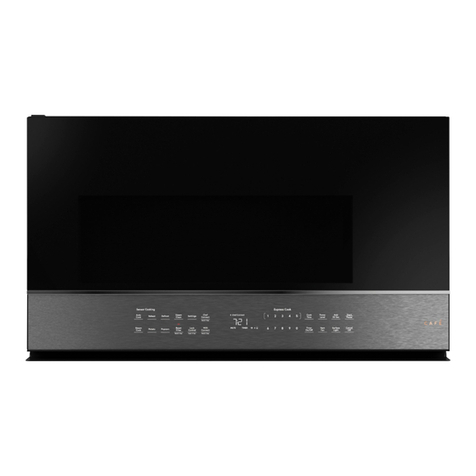
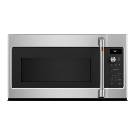
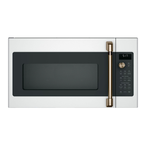
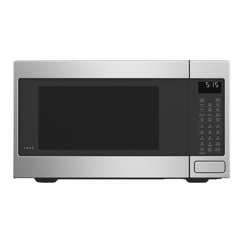
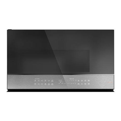
Cafe CVM517P User manual

Installation
Instructions
CANADA only
Over the Range
Microwave Oven
CVM517P
The power cord of this appliance is
equipped with a 125 Volt NEMA 5-20 three
prong plug which mates with a NEMA 5-20
three-prong (grounding) wall receptacle to
minimize the possibility of electric shock
hazard from this appliance.
ELECTRICAL REQUIREMENTS
Product rating is 120 volts AC, 60 Hertz, 20 amps and 1.75
kilowatts.
This product must be connected to a supply circuit of the
proper voltage and frequency. Wire size must conform to
the requirements of the National Electrical Code or the
prevailing local code for this kilowatt rating.
The power supply cord and plug should be brought to a
separate 20-ampere branch circuit single grounded
outlet.
The outlet box should be located in the cabinet above the
microwave oven. The outlet box and supply circuit should
be installed by a qualified electrician and conform to the
National Electrical Code or the prevailing local code.

READ CAREFULLY.
KEEP THESE INSTRUCTIONS.
31-2000103 09-18 GEA
LA SECCIÛN EN ESPAÒOL
EMPIEZA EN LA P·GINA 25.
Over the Range
Microwave Oven
Installation
Instructions
BEFORE YOU BEGIN
Read these instructions carefully and completely.
Ŷ IMPORTANT – Save these instructions for
local inspector’s use.
Ŷ IMPORTANT – Observe all governing codes
and ordinances.
Ŷ Note to Installer – Be sure to leave these instructions
with Consumer.
Ŷ Note to Consumer – Keep these instructions for
future reference.
Ŷ Skill level – Installation of this appliance requires
basic mechanical and electrical skills.
Ŷ 3URSHULQVWDOODWLRQLVWKHUHVSRQVLELOLW\RIWKHLQVWDOOHU
Ŷ 3URGXFWIDLOXUHGXHWRLPSURSHULQVWDOODWLRQLVQRW
FRYHUHGXQGHU:DUUDQW\

2
Outside Back Exhaust ............................16-19
3UHSDULQJ5HDU:DOOIRU
Outside Back Exhaust ........................ 16
$WWDFK0RXQWLQJ3ODWHWR:DOO .......16 17
3UHSDUDWLRQRI7RS&DELQHW ................17
Adapting Microwave Blower
for Outside Back Exhaust ............. 17, 18
Mount the Microwave Oven ............... 19
5HFLUFXODWLQJ ......................................... 20-23
$WWDFK0RXQWLQJ3ODWHWR:DOO ........... 20
3UHSDUDWLRQRI7RS&DELQHW ............... 20
Check Blower Motor Orientation ........ 21
Adapting Microwave Blower
IRU5HFLUFXODWLRQ ........................... 21, 22
Mount the Microwave Oven ......... 22, 23
Installing the Charcoal Filter .............. 23
Before You Use Your Microwave ...................... 24
CONTENTS
General information
Important Safety Instructions .............................. 3
Electrical Requirements ........................................ 3
Hood Exhaust .................................................... 4, 5
Damage – Shipment/Installation .......................... 6
Parts Included ........................................................ 6
Tools You Will Need .............................................. 7
Mounting Space ..................................................... 7
Step-by-step Installation Guide
Placement of Mounting Plate ......................... 8–10
5HPRYLQJWKH0RXQWLQJ3ODWH ...................... 8
Finding the Wall Studs ................................. 8
'HWHUPLQLQJ:DOO3ODWH/RFDWLRQ .................. 9
$OLJQLQJWKH:DOO3ODWH ............................... 10
Installation Types .......................................... 11–23
2XWVLGH7RS([KDXVW ............................ 12–15
$WWDFK0RXQWLQJ3ODWHWR:DOO ............12
3UHSDUDWLRQRI7RS&DELQHW ................13
Check Blower Motor Orientation .........13
Adapting Blower for Outside
Ventilation .....................................13, 14
&KHFNIRU3URSHU'DPSHU
Operation ............................................14
Mount the Microwave Oven ..........14, 15
Adjust the Exhaust Adaptor ................15
Connecting Ductwork .......................... 15
A
C
Installation Instructions
B

3
IMPORTANT SAFETY INSTRUCTIONS
A qualified electrician must perform a ground
FRQWLQXLW\FKHFNRQWKHZDOOUHFHSWDFOHEHIRUH
beginning the installation to ensure that the
RXWOHWER[LVSURSHUO\JURXQGHG,IQRWSURSHUO\
grounded, or if the wall receptacle does not meet
HOHFWULFDOUHTXLUHPHQWVQRWHGXQGHU(/(&75,&$/
5(48,5(0(176DTXDOLILHGHOHFWULFLDQVKRXOGEH
HPSOR\HGWRFRUUHFWDQ\GHILFLHQFLHV
Risk of Electric Shock.
Can cause injury or
death: Remove house
fuse or
open circuit breaker
before beginning
installation to avoid
severe or fatal shock
injury.
Risk of Electric
Shock. Can cause
injury or death: THIS
APPLIANCE MUST
BE PROPERLY
GROUNDED to avoid
severe or fatal shock.
The power cord of this appliance is equipped
with a three-prong (grounding) plug which mates
with a standard three-prong (grounding) wall
receptacle to minimize the possibility of electric
shock hazard from this appliance.
Where a standard two-prong wall receptacle is
encountered, it must be replaced with a properly
grounded three-prong wall receptacle, installed by
a qualified electrician.
Installation Instructions
Ensure
proper
ground
exists before
use
FOR YOUR SAFETY:
For personal safety,
the mounting surface must be
capable of supporting the cabinet load, in addition to
the added weight of this 63–85 pound product, plus
additional oven loads of up to 50 pounds or a total
weight of 113–135 pounds.
For personal safety, this product
cannot be installed in cabinet
arrangements such as an island or a peninsula. It must
EHPRXQWHGWR%27+DWRSFDELQHW$1'DZDOO
To avoid the risk of personal
injuryEDFNLQMXU\RURWKHULQMXULHV
GXHWRH[FHVVLYHZHLJKWRIWKHPLFURZDYHRYHQRU
SURSHUW\GDPDJH\RXZLOOQHHGWZRSHRSOHWRLQVWDOO
this microwave oven.
ELECTRICAL REQUIREMENTS
3URGXFWUDWLQJLVYROWV$&+HUW]
DPSVDQGNLORZDWWV7KLVSURGXFWPXVWEH
FRQQHFWHGWRDVXSSO\FLUFXLWRIWKHSURSHUYROWDJH
DQGIUHTXHQF\:LUHVL]HPXVWFRQIRUPWRWKH
UHTXLUHPHQWVRIWKH1DWLRQDO(OHFWULFDO&RGHRUWKH
SUHYDLOLQJORFDOFRGHIRUWKLVNLORZDWWUDWLQJ7KH
SRZHUVXSSO\FRUGDQGSOXJVKRXOGEHEURXJKWWR
a separate 15- to 20-ampere branch circuit single
JURXQGHGRXWOHW7KHRXWOHWER[VKRXOGEHORFDWHG
LQWKHFDELQHWDERYHWKHPLFURZDYHRYHQ7KH
RXWOHWER[DQGVXSSO\FLUFXLWVKRXOGEHLQVWDOOHGE\
DTXDOLILHGHOHFWULFLDQDQGFRQIRUPWRWKH1DWLRQDO
Electrical Code or the prevailing local code.
CAUTION
CAUTION
CAUTION
RISK OF ELECTRIC SHOCK
Can cause injury or death: DO
NOT, under any circumstances,
cut, deform or remove any of the prongs from the
power cord. Do not use with an extension cord.
Failure to comply may cause fire.
WARNING
WARNING
WARNING
4
HOOD EXHAUST
7KHIROORZLQJFKDUWGHVFULEHVDQH[DPSOHRIRQHSRVVLEOH
ductwork installation.
127(5HDGWKHVHQH[WWZRSDJHVRQO\LI\RXSODQWRYHQW\RXUH[KDXVWWRWKHRXWVLGH,I\RXSODQWRUHFLUFXODWHWKHDLUEDFN
into the room, proceed to page 11.
OUTSIDE TOP EXHAUST (EXAMPLE ONLY)
NOTE: For back exhaust, care should be taken to align exhaust with space between studs, or wall
VKRXOGEHSUHSDUHGDWWKHWLPHLWLVFRQVWUXFWHGE\OHDYLQJHQRXJKVSDFHEHWZHHQWKHZDOOVWXGVWR
accommodate exhaust.
* IMPORTANT: If a rectangular-to-round transition adaptor is used, the bottom corners of the damper
will have to be cut to fit, using the tin snips, in order to allow free movement of the damper.
7KHIROORZLQJFKDUWGHVFULEHVDQH[DPSOHRIRQHSRVVLEOH
ductwork installation.
Installation Instructions
OUTSIDE BACK EXHAUST (EXAMPLE ONLY)
EQUIVALENT NUMBER
DUCT PIECES LENGTH x USED = LENGTH
5RRI&DS )W [ )W
)W6WUDLJKW'XFW )W [ )W
(6s5RXQG
5HFWDQJXODUWR5RXQG )W [ )W
7UDQVLWLRQ$GDSWRU
Equivalent lengths of duct pieces are based on actual tests and
UHIOHFWUHTXLUHPHQWVIRUJRRGYHQWLQJSHUIRUPDQFHZLWKDQ\YHQWKRRG
Total Length = 41 Ft.
EQUIVALENT NUMBER
DUCT PIECES LENGTH* x USED = LENGTH
:DOO&DS )W [ )W
)W6WUDLJKW'XFW )W [ )W
(31»4s x 10s5HFWDQJXODU
(OERZ )W [ )W
Equivalent lengths of duct pieces are based on actual tests and
UHIOHFWUHTXLUHPHQWVIRUJRRGYHQWLQJSHUIRUPDQFHZLWKDQ\YHQWKRRG
Total Length = 63 Ft.

5
EQUIVALENT NUMBER
DUCT PIECES LENGTH x USED = LENGTH
5HFWDQJXODUWR5RXQG )W [ )W
7UDQVLWLRQ$GDSWRU
:DOO&DS )W [ )W
(OERZ )W [ )W
(OERZ )W [ )W
(OERZ )W [ )W
(OERZ )W [ )W
5RRI&DS )W [ )W
Straight Duct 6s5RXQGRU )W [ )W
3
1»4s x 10s5HFWDQJXODU
Total Ductwork = Ft.
Equivalent lengths of duct pieces are based on actual tests
and reflect requirements for good venting performance with
DQ\YHQWKRRG
IMPORTANT: If a rectangular-to-round transition
adaptor is used, the bottom corners of the
damper will have to be cut to fit, using the tin
snips, in order to allow free movement of the
damper
.
Installation Instructions
NOTE: ,I\RXQHHGWRLQVWDOOGXFWVQRWHWKDWWKHWRWDO
duct length of 31»4Ǝ[ƎUHFWDQJXODURUƎGLDPHWHUURXQG
duct should not exceed 140 equivalent feet.
2XWVLGHYHQWLODWLRQUHTXLUHVD+22'(;+$867'8&7
5HDGWKHIROORZLQJFDUHIXOO\
NOTE: It is important that venting be installed using
the most direct route and with as few elbows as possible.
7KLVHQVXUHVFOHDUYHQWLQJRIH[KDXVWDQGKHOSVSUHYHQW
blockages. Also, make sure dampers swing freely and
nothing is blocking the ducts.
Exhaust connection:
7KHKRRGH[KDXVWKDVEHHQGHVLJQHGWRPDWHZLWK
a standard 31»4Ǝ[ƎUHFWDQJXODUGXFW
If a round duct is required, a rectangular-to-round
transition adaptor must be used. Do not use less than
a 6Ǝ diameter duct.
Maximum duct length:
)RUVDWLVIDFWRU\DLUPRYHPHQWWKHWRWDOGXFWOHQJWKRI
31»4s x 10s rectangular or 6s diameter round duct should
not exceed 140 equivalent feet.
Elbows, transitions, wall and roof caps,
etc., present additional resistance to airflow and are
equivalent to a section of straight duct which is longer
WKDQWKHLUDFWXDOSK\VLFDOVL]H:KHQFDOFXODWLQJWKHWRWDO
duct length, add the equivalent lengths of all transitions
and adaptors plus the length of all straight duct sections.
7KHFKDUWEHORZVKRZV\RXKRZWRFDOFXODWHWRWDO
equivalent ductwork length using the approximate feet of
HTXLYDOHQWOHQJWKRIVRPHW\SLFDOGXFWV

6
HARDWARE PACKET
PART QUANTITY
7RS&DELQHW
1
7HPSODWH
5HDU:DOO
7HPSODWH
Installation 1
Instructions
6HSDUDWHO\
2
3DFNHG
Grease
Filter
PART QUANTITY
Wood Screws 2
(
1»4s x 2s
7RJJOH%ROWVDQG
ZLQJQXWV
(
3»16s x 3s
Self-Aligning
Machine
Screws 3
(
1»4s-28 x 31»4s
1\ORQ*URPPHW
IRUPHWDOFDELQHWV
DAMAGE – SHIPMENT INSTALLATION
• If the unit is damaged in shipment, return the
unit to the store in which it was bought for repair or
replacement.
• If the unit is damaged by the customer, repair or
UHSODFHPHQWLVWKHUHVSRQVLELOLW\RIWKHFXVWRPHU
• If the unit is damaged by the installer (if other
WKDQWKHFXVWRPHUUHSDLURUUHSODFHPHQWPXVW
EHPDGHE\DUUDQJHPHQWEHWZHHQFXVWRPHUDQG
installer.
PARTS INCLUDED
You will find the installation hardware contained in a
SDFNHWZLWKWKHXQLW&KHFNWRPDNHVXUH\RXKDYH
all these parts.
NOTE: Some extra parts are included.
ADDITIONAL PARTS
Installation Instructions

7
TOOLS YOU WILL NEED
DQG3KLOOLSV
screwdriver
3HQFLO
5XOHURUWDSHPHDVXUH
and straight edge Carpenter square
RSWLRQDO
7LQVQLSVIRUFXWWLQJ
GDPSHULIUHTXLUHG
Electric drill with 3»16s, 1»2s
and 5»8s drill bits
+DPPHURSWLRQDO
Stud finder or
Filler blocks or scrap
wood pieces, if needed
for top cabinet spacing
(used on recessed
bottom cabinet
LQVWDOODWLRQVRQO\
Gloves
Saw (saber, hole or
NH\KROH
/HYHO Duct and masking
tape
MOUNTING SPACE NOTES:
7KHVSDFHEHWZHHQWKHFDELQHWVPXVWEH
30s wide and free of obstructions.
• If the space between the cabinets is greater
than 30sD)LOOHU3DQHO.LWPD\EHXVHGWRILOO
in the gap between the microwave oven and
the cabinets. Your Owner’s Manual contains
WKHNLWQXPEHUIRU\RXUPRGHO
7KLVPLFURZDYHRYHQLVIRULQVWDOODWLRQRYHU
ranges up to 36s wide.
,I\RXDUHJRLQJWRYHQW\RXUPLFURZDYHRYHQ
WRWKHRXWVLGHVHH+RRG([KDXVW6HFWLRQIRU
exhaust duct preparation.
• When installing the microwave oven beneath
smooth, flat cabinets, be careful to follow the
instructions on the top cabinet template for
power cord clearance.
• Models with top venting grilles: Do not
allow cabinetry or other objects to block the
airflow
of the vent.
13” max: for standard installation, 15”
cabinet depth requires additional steps using
an additional installation kit JX15BUMPWW/
BB.
Backsplash
66s or More
from the
Floor to the
7RSRIWKH
Microwave
30s
2s
30s
min.
161»2s
Bottom Edge
of Cabinet
1HHGVWR
be 30s or
More from
the Cooking
Surface
Installation Instructions
Scissors
(to cut template, if
QHFHVVDU\
6DIHW\JRJJOHV
13s
PD[
Minimum
distance from
door hinge side
to adjacent wall
should
equal 3/4”

8
Find the studs, using one of the following
PHWKRGV
A. Stud finder – a magnetic device which
locates nails.
OR
B8VHDKDPPHUWRWDSOLJKWO\DFURVVWKH
mounting surface to find a solid sound.
7KLVZLOOLQGLFDWHDVWXGORFDWLRQ
$IWHUORFDWLQJWKHVWXGVILQGWKHFHQWHUE\
probing the wall with a small nail to find the edges
RIWKHVWXG7KHQSODFHDPDUNKDOIZD\EHWZHHQ
WKHHGJHV7KHFHQWHURIDQ\DGMDFHQWVWXGV
should be 16s or 24s from this mark.
Draw a line down the center of the studs.
NOTE: THE MICROWAVE MUST BE
CONNECTED TO AT LEAST ONE WALL STUD.
1
5HPRYHWKHLQVWDOODWLRQLQVWUXFWLRQVILOWHUVJODVV
WUD\DQGWKHVPDOOKDUGZDUHEDJ'RQRWUHPRYH
the foam protecting the front of the oven.
)ROGEDFNDOOFDUWRQIODSVIXOO\DJDLQVWFDUWRQ
VLGHV7KHQFDUHIXOO\UROOWKHRYHQDQGFDUWRQRYHU
RQWRWKHWRSVLGH7KHRYHQVKRXOGEHUHVWLQJLQ
the foam.
REMOVING THE MICROWAVE OVEN
FROM THE CARTON/REMOVING
THE MOUNTING PLATE
FINDING THE WALL STUDS
B.
A.
2
PLACEMENT OF THE MOUNTING PLATE
1
Wall
Studs
Center
3
Carton
3XOOWKHFDUWRQXSDQGRIIWKHRYHQ
5HPRYHWKHVFUHZVIURPWKHPRXQWLQJSODWH
7KLVSODWHZLOOEHXVHGDVWKHUHDUZDOOWHPSODWH
DQGIRUPRXQWLQJ<RXPD\GLVFDUGWKHVHVFUHZV
Mounting
3ODWH
Screws
foam
Installation Instructions
2
3
5
5HPRYHDQGSURSHUO\GLVFDUGSODVWLFEDJV
4
1

9
DETERMINING WALL PLATE LOCATION UNDER YOUR CABINET
C.
<RXUFDELQHWVPD\KDYHGHFRUDWLYHWULPWKDW
LQWHUIHUHVZLWKWKHPLFURZDYHLQVWDOODWLRQ5HPRYHWKH
GHFRUDWLYHWULPWRLQVWDOOWKHPLFURZDYHSURSHUO\DQG
to make it level.
NOTE: THE MICROWAVE MUST BE LEVEL.
8VHDOHYHOWRPDNHVXUHWKHFDELQHWERWWRPLVOHYHO
,IWKHFDELQHWVKDYHDIURQWRYHUKDQJRQO\ZLWKQR
back or side frame, install the mounting plate down
WKHVDPHGLVWDQFHDVWKHIURQWRYHUKDQJGHSWK7KLV
will keep the microwave level.
Measure the inside depth of the front overhang.
'UDZDKRUL]RQWDOOLQHRQWKHEDFNZDOODQHTXDO
distance below the cabinet bottom as the inside
depth of the front overhang.
)RUWKLVW\SHRILQVWDOODWLRQZLWKIURQWRYHUKDQJRQO\
DOLJQWKHPRXQWLQJWDEVZLWKWKLVKRUL]RQWDOOLQHQRW
touching the cabinet bottom as described in Step D.
Plate position – beneath flat bottom
cabinet
Plate position – beneath recessed bottom
cabinet with front overhang
0RXQWLQJ3ODWH7DEV
7RXFKLQJWKH&DELQHW
Bottom
0RXQWLQJ3ODWH
ZLWK7DEV%HORZ
Cabinet Bottom the
Same Distance as
the Front Overhang
Depth
At least 30s, up to 36s
Plate position – beneath framed recessed
cabinet bottom
0RXQWLQJ3ODWH
7DEV7RXFKLQJWKH
Back Frame
Installation Instructions
30s to Cooktop
30s to Cooktop
1
2
3

10
ALIGNING THE WALL PLATE
Wear gloves to avoid cutting
fingers on sharp edges.
Draw a vertical line on the wall at the center of the
30s wide space.
8VHWKHPRXQWLQJSODWHas the template for the rear
ZDOO3ODFHWKHPRXQWLQJSODWHRQWKHZDOOPDNLQJ
sure that the tabs are touching the bottom of the
cabinet or the level line drawn in Step C for
cabinets with front overhang. Line up the notch
and centerline on the bottom of the mounting
plate to the centerline on the wall.
While holding the mounting plate with one hand,
draw circles on the wall at holes A, B, C and D
(see illustration above/actual plate marked with
DUURZVFour holes must be used for mounting.
NOTE:+ROHV&DQG'DUHLQVLGHDUHD(,IQHLWKHU
C nor D is in a stud, find a stud somewhere in area
E and draw a fifth circle to line up with the stud. It is
important to use at least one wood screw mounted
firmly in a stud to support the weight of the
microwave.
Set the mounting plate aside.
Risk of electric shock. Can
cause injury or death. Take
care to not drill into electrical wiring inside walls
or cabinets.
Drill holes on the circles. If there is a stud, drill a 3»16s
hole for wood screws. For holes that don’t line up
with a stud, drill a 5»8s hole for toggle bolts. Drill two
5»8” holes for toggle screws.
NOTE: DO NOT MOUNT THE PLATE AT THIS TIME.
1
2
34
Draw a Vertical
/LQHRQ:DOO
from Center of
7RS&DELQHW
Area E
+ROH$ +ROH%
+ROH'
+ROH&
D.
Installation Instructions
Centerline
1RWFKHV
CAUTION
WARNING

11
A
INSTALLATION TYPES
(Choose A, B or C)
7KLVPLFURZDYHRYHQLVGHVLJQHGIRUDGDSWDWLRQWR
WKHIROORZLQJWKUHHW\SHVRIYHQWLODWLRQ
A. Outside Top Exhaust (Vertical Duct)
B. Outside Back Exhaust (Horizontal Duct)
C. Recirculating (Non-Vented Ductless)
NOTE:7KLVPLFURZDYHLVVKLSSHGDVVHPEOHGIRU2XWVLGH
7RS([KDXVWH[FHSWIRUQRQYHQWHGPRGHOV6HOHFWWKH
W\SHRIYHQWLODWLRQUHTXLUHGIRU\RXULQVWDOODWLRQDQG
proceed to that section.
OUTSIDE TOP EXHAUST
(VERTICAL DUCT)
OUTSIDE BACK EXHAUST
(HORIZONTAL DUCT)
RECIRCULATING
(NON-VENTED DUCTLESS)
See page 12
See page 16
See page 20
$&KDUFRDO)LOWHU$FFHVVRU\.LWLVUHTXLUHGIRUWKH
QRQYHQWHGH[KDXVW6HH\RXU2ZQHU¶V0DQXDOIRU
WKHNLWQXPEHU
$GDSWRULQ3ODFH
IRU2XWVLGH7RS
Exhaust
Installation Instructions
2
B
C

12
3ODFHWKHPRXQWLQJSODWHDJDLQVWWKHZDOODQG
insert the toggle wings into the holes in the wall
to mount the plate.
NOTE: Before tightening toggle bolts and wood
screw, make sure the tabs on the mounting plate
touch the bottom of the cabinet when pushed
flush against the wall and that the plate is
SURSHUO\FHQWHUHGXQGHUWKHFDELQHW
Be careful to avoid
pinching fingers between the back of the
mounting plate
and the wall.
7LJKWHQDOOEROWV3XOOWKHSODWHDZD\IURPWKHZDOO
to help tighten the bolts.
3
A
4
OUTSIDE TOP EXHAUST
(Vertical Duct)
INSTALLATION OVERVIEW
A1.$WWDFK0RXQWLQJ3ODWHWR:DOO
A23UHSDUH7RS&DELQHW
A3. Check Blower Motor Oientation
A4. Adapt Blower for Outside Ventilation
A5. Check Damper Operation
A6. Mount Microwave Oven
A7. Adjust Exhaust Adaptor
A8. Connect Ductwork
Wall
Mounting
3ODWH
6SDFLQJIRU7RJJOHV0RUH
7KDQ:DOO7KLFNQHVV
Bolt End
7RJJOH
Bolt
7RJJOH:LQJV
To use toggle bolts:
Installation Instructions
ATTACH THE MOUNTING PLATE
TO THE WALL
A1
Attach the plate to the wall using toggle bolts. At
least one wood screw must be used to attach the
plate to
DZDOOVWXG5HFRPPHQGHGORFDWLRQVRQWKH
PRXQWLQJSODWHDUHLQGLFDWHGE\$%&DQG'
5HPRYHWKHWRJJOHZLQJVIURPWKHEROWV
Insert the bolts into the mounting plate through
WKHKROHVGHVLJQDWHGWRJRLQWRGU\ZDOODQG
reattach the toggle wings to 3»4s onto each bolt.
1
2
AB
CD
CAUTION

13
USE TOP CABINET TEMPLATE
FOR PREPARATION OF TOP
CABINET
You need to drill holes for the top support screws, a
hole large enough for the power cord to fit through,
and a cutout large enough for the exhaust adaptor.
CHECK BLOWER MOTOR
ORIENTATION
7KHEORZHUIDQEODGHRSHQLQJVKRXOGEHIDFLQJWKH
WRSRIWKHPLFURZDYH,IWKHIDQRSHQLQJLVDOUHDG\
facing the top of the microwave, skip to Step A5.
Otherwise, continue to Step A4 to adjust the motor
orientation.
ADAPTING BLOWER FOR
OUTSIDE VENTILATION
5HPRYHDQGVDYHWKHVFUHZVWKDWKROGWKHEORZHU
motor to the microwave oven.
5HPRYHDQGVDYHWKHPHWDOEORZHUVKLHOGRQWKH
WRSRIWKHPLFURZDYHE\VOLGLQJLWULJKW
ADAPTING BLOWER FOR
OUTSIDE VENTILATION (Cont.)
Attached the metal blower shield to the backside
RIWKHPLFURZDYHRYHQE\VOLGLQJLWGRZQ
2SHQWKHEORZHUGRRUE\OLIWLQJLWXSDWWKHEDFNRI
the microwave oven.
&DUHIXOO\SXOORXWWKHEORZHUXQLW7KHZLUHVZLOO
H[WHQGIDUHQRXJKWRDOORZ\RXWRDGMXVWWKH
blower unit.
5ROOWKHEORZHUXQLWÛVRWKDWWKHIDQEODGH
openings are facing the top.
A2.
A3.
A4.
A4.
5HDGWKHLQVWUXFWLRQVRQWKH723&$%,1(7
7(03/$7(
7DSHLWXQGHUQHDWKWKHWRSFDELQHW
• Drill the holes, following the instructions on the
723&$%,1(77(03/$7(
NOTE: Wear safety goggles when drilling holes
in the cabinet bottom.
Installation Instructions
1
3
4
5
6
2
Back of Oven
Blower Motor
Screws
%ORZHU3ODWH
BEFORE: Fan
Blade Openings
Facing Forward
AFTER: Fan
Blade Openings
Facing Up
Blower
Shield
5ROO
127(0DNH
sure wires
remain routed
in the grooves
of the motor
frame.
Blower Motor
Screw

14
Installation Instructions
ADAPTING BLOWER FOR
OUTSIDE VENTILATION (Cont.)
3ODFHWKHEORZHUXQLWEDFNLQWRWKHRSHQLQJ
Do not pull or stretch the
blower unit wiring. Make
sure the wires are not pinched.
Close the blower door. Secure the blower to the
microwave using the screws from Step 1.
A4.
7
8
CHECK FOR PROPER
DAMPER OPERATION
A5.
Exhaust Adaptor
%ORZHU3ODWH
Damper
Back of
Microwave
Oven
3ODFHWKHPLFURZDYHLQLWVXSULJKWSRVLWLRQZLWKWKH
top of the unit facing up.
• Make sure tape securing damper is removed
and damper pivots easily before mounting
microwave.
• Slide the damper into place. Make sure it catches
in the retaining hooks to secure.
• You will need to make adjustments to assure
SURSHUDOLJQPHQWZLWK\RXUKRXVHH[KDXVWGXFW
after the microwave is installed.
5HWDLQLQJ+RRNV
3
MOUNT THE MICROWAVE
OVEN
A6.
FOR EASIER INSTALLATION
AND PERSONAL SAFETY,
WE RECOMMEND THAT TWO PEOPLE INSTALL
THIS MICROWAVE OVEN.
IMPORTANT: Do not grip or use handle
during installation.
NOTE:,I\RXUFDELQHWLVPHWDOXVHWKHQ\ORQ
grommet around the power cord hole to prevent
cutting of the cord.
NOTE: We recommend using filler blocks if the
cabinet front hangs below the cabinet bottom shelf.
IMPORTANT: If filler blocks are not
used, case damage may occur from
overtightening screws.
Insert a self-aligning screw through top center
FDELQHWKROH7HPSRUDULO\VHFXUHWKHRYHQE\
turning the screw at least two full turns after
WKHWKUHDGVKDYHHQJDJHG,WZLOOEHFRPSOHWHO\
WLJKWHQHGODWHUBe sure to keep power cord tight.
Be careful not to pinch the cord, especially
when mounting flush to bottom of cabinet.
NOTE: When mounting
the microwave oven,
thread power cord
through hole in bottom of
top cabinet. Keep it tight
throughout Steps 1–3. Do
not pinch cord or lift oven
E\SXOOLQJFRUG
/LIWPLFURZDYHWLOWLW
forward, and hook
slots at back bottom
edge onto four lower
tabs of mounting
plate.
1
25RWDWHIURQWRIRYHQ
up against cabinet
bottom.
CAUTION
CAUTION

15
4
Attach the microwave oven to the top cabinet.
7
6
Cabinet Front
Cabinet Bottom Shelf
7LJKWHQWKHRXWHUWKUHHVFUHZVWRWKHWRSRIWKH
microwave oven. (While tightening screws, hold
the microwave oven in place against the wall
DQGWKHWRSFDELQHW
Install grease filter. See the Owner’s Manual on
WKHZHEVLWH*($SSOLDQFHVFRP
Filler Block
0LFURZDYH2YHQ7RS
Equivalent
to Depth
of Cabinet
5HFHVV
Insert 3 self-aligning screws through outer top
FDELQHWKROHV7XUQWZRIXOOWXUQVRQHDFKVFUHZ
Installation Instructions
ADJUST THE EXHAUST
ADAPTOR
A7.
Open the top cabinet and adjust the exhaust adaptor
to connect to the house duct.
Back of
Microwave Oven
For Side-to-Side Adjustment,
Slide the Exhaust Adaptor as
1HHGHG
Damper
CONNECTING DUCTWORK
1
2
Extend the house duct down to connect to
the exhaust adaptor.
Seal exhaust duct joints using duct tape.
A8.
+RXVH'XFW
Self-Aligning Screw
5
MOUNT THE MICROWAVE
OVEN (cont.)
A6.
T
u
r
n
t
o
S
e
l
e
c
t
P
r
e
s
s
t
o
E
n
t
e
r
Reheat
Timer
On/Off
Defrost
Weight/Time
Start
Pause
Cancel
Off
LockControls
Hold3Sec
Cook
Time
Set
Clock
Options Help
Surface
Light VentFan
Popcorn
B
everage
Microwave
Express
Warm Power
Level
Auto
Cook
Combination
FastBake
Convection
Roast
Turntable
Convection
Bake

16
OUTSIDE BACK EXHAUST
(Horizontal Duct)
INSTALLATION OVERVIEW
B1.3UHSDUH5HDU:DOO
B2. $WWDFK0RXQWLQJ3ODWHWR:DOO
B3.3UHSDUH7RS&DELQHW
B4. Adjust Blower
B5. Mount the Microwave Oven
Installation Instructions
B
PREPARING THE REAR WALL
FOR OUTSIDE BACK EXHAUST
B1.
You need to cut an opening in the rear wall for
outside exhaust.
5HDGWKHLQVWUXFWLRQVRQWKH5($5:$//
7(03/$7(
7DSHLWWRWKHUHDUZDOOOLQLQJXSZLWKWKHKROHV
SUHYLRXVO\GULOOHGIRUKROHV$DQG%LQWKHZDOO
plate.
• Cut the opening, following the instructions of the
5($5:$//7(03/$7(
ATTACH THE MOUNTING
PLATE TO THE WALL
B2.
Attach the plate to the wall using toggle bolts. At
least one wood screw must be used to attach the
SODWHWRDZDOOVWXG5HFRPPHQGHGORFDWLRQVRQ
WKHPRXQWLQJSODWHDUHLQGLFDWHGE\$%&DQG'
5HPRYHWKHWRJJOHZLQJVIURPWKHEROWV
Insert the bolts into the mounting plate through
WKHKROHVGHVLJQDWHGWRJRLQWRGU\ZDOODQG
reattach the toggle wings to 3»4s onto each bolt.
1
2
AB
CD

17
USE TOP CABINET TEMPLATE
FOR PREPARATION OF TOP
CABINET
B3.
5HDGWKHLQVWUXFWLRQVRQWKH723&$%,1(7
7(03/$7(
7DSHLWXQGHUQHDWKWKHWRSFDELQHW
• Drill the holes, following the instructions on the
723&$%,1(77(03/$7(
Wear safety goggles when
drilling holes in the cabinet bottom.
Wall
Mounting
3ODWH
6SDFLQJIRU7RJJOHV0RUH
7KDQ:DOO7KLFNQHVV
7RJJOH
Bolt
7RJJOH:LQJV
To use toggle bolts:
Bolt End
Installation Instructions
You need to drill holes for the top support screws and
a hole large enough for the power cord to fit through.
3ODFHWKHPRXQWLQJSODWHDJDLQVWWKHZDOODQG
insert the toggle wings into the holes in the wall
to mount the plate.
NOTE: Before tightening toggle bolts and wood
screw, make sure the tabs on the mounting plate
touch the bottom of the cabinet when pushed
IOXVKDJDLQVWWKHZDOODQGWKDWWKHSODWHLVSURSHUO\
centered under the cabinet.
Be careful to avoid pinching
fingers between the back of the mounting plate
and the wall.
7LJKWHQDOOEROWV3XOOWKHSODWHDZD\IURPWKHZDOO
to help tighten the bolts.
3
4
1
5HPRYHDQGVDYHscrews that holds blower
motor to microwave oven.
ADAPTING MICROWAVE
BLOWER FOR OUTSIDE BACK
EXHAUST
B4.
Back of Microwave Oven
2
2SHQWKHEORZHUGRRUE\OLIWLQJLWXSDWWKHEDFN
RIWKHPLFURZDYH5HPRYHDQGVDYHWKHEORZHU
VKLHOGRQWKHEDFNRIWKHPLFURZDYHE\VOLGLQJLW
up.
5HPRYHDQGVDYHWKHPHWDOYHQWIDQFRYHURQ
WKHEDFNRIWKHPLFURZDYHE\VOLGLQJLWXS
4
5RWDWHEORZHUXQLWFRXQWHUFORFNZLVH
%HIRUH5RWDWLRQ $IWHU5RWDWLRQ
Back of Microwave Oven Back of Microwave Oven
3
BEFORE: Fan Blade
Openings Facing Up
End B
End A
&DUHIXOO\SXOORXWWKHEORZHUXQLW7KHZLUHV
ZLOOH[WHQGIDUHQRXJKWRDOORZ\RXWRDGMXVWWKH
blower unit.
%ORZHU5HWDLQLQJ
Screws
CAUTION
CAUTION

18
Installation Instructions
ADAPTING MICROWAVE
BLOWER FOR OUTSIDE BACK
EXHAUST (cont.)
B4.
5ROOWKHEORZHUXQLWVRWKDWIDQEODGH
openings are facing out the back of the
microwave.
5 *HQWO\UHPRYHWKHZLUHVIURPWKHJURRYHV
5HURXWHWKHZLUHVWKURXJKJURRYHVRQRWKHUVLGH
of the blower unit.
%HIRUH5HURXWLQJ $IWHU5HURXWLQJ
:LUHV5RXWHG7KURXJK
5LJKW6LGH
:LUHV5RXWHG7KURXJK/HIW
Side
%HIRUH5ROOLQJ $IWHU5ROOLQJ
Back of
Microwave
Oven
Back of
Microwave Oven
6
/RFDWHWKHWZR³NQRFNRXW´SODWHVRQWKHUHDU
RYHQSDQHOQHDUWKHWRSRIWKHRYHQ8VLQJWLQ
VQLSVFDUHIXOO\FXWWKHZHEDUHDIURPWKHWZR
KROHVVLGHE\VLGHWKDWVHFXUHWKHNQRFNRXWV
WRWKHRYHQ&XWDOOIRXUZHEVRQERWKUHDU
knockouts; this will allow the ventilation fan
airflow to exhaust out the rear of the oven.
Be sure to trim the sharp
edges from the openings
after removing the knockout plates.
7
9
Close the blower door. Slide blower shield onto
the top of the blower door opening. Secure the
blower to the microwave oven using the blower
retaining screws from Step 1 except the upper
blower motor retaining screw
Back of
Microwave
Oven
Blower
5HWDLQLQJ
Screw
%ORZHU5HWDLQLQJ
Screw
Blower Shield
AFTER: Fan Blade
Openings Facing Back
8
3ODFHWKHEORZHUXQLWEDFNLQWRWKHRSHQLQJ
7KHEORZHUXQLWH[KDXVWRSHQLQJVVKRXOG
match exhaust openings on rear of microwave.
Do not pull or stretch
the blower unit wiring. Make sure the wires
are not pinched.
End A
End B
Slide the exhaust adaptor onto the back
of the microwave oven, securing it into the
ORZHUORFNLQJWDEV7DNHFDUHWRHQVXUHWKDW
the damper hinge is installed so that it is at
WKHWRSDQGWKDWWKHGDPSHUVZLQJVIUHHO\
5HLQVWDOOWKHXSSHUEORZHUPRWRUVFUHZ
through the adaptor and the blower door and
into the back of the microwave oven.
10
Guide
Guide
Adaptor /RFNLQJ7DEV
QRWVKRZQ
Back of
Microwave Oven
Blower Motor
'RRU5HWDLQLQJ
Screw
CAUTION
CAUTION

19
Installation Instructions
Attach the microwave oven to the top cabinet.
Insert 3 self-aligning screws through outer top
FDELQHWKROHV7XUQWZRIXOOWXUQVRQHDFKVFUHZ
3
MOUNT THE MICROWAVE
OVEN
B5.
FOR EASIER INSTALLATION
AND PERSONAL SAFETY,
WE RECOMMEND THAT TWO PEOPLE INSTALL
THIS MICROWAVE OVEN.
IMPORTANT: Do not grip or use handle
during installation.
NOTE:,I\RXUFDELQHWLVPHWDOXVHWKHQ\ORQ
grommet around the power cord hole to prevent
cutting of the cord.
NOTE: We recommend using filler blocks if the
cabinet front hangs below the cabinet bottom shelf.
IMPORTANT: If filler blocks are not
used, case damage may occur from
overtightening screws.
Insert a self-aligning screw through top center
FDELQHWKROH7HPSRUDULO\VHFXUHWKHRYHQE\
turning the screw at least two full turns after the
WKUHDGVKDYHHQJDJHG,WZLOOEHFRPSOHWHO\
WLJKWHQHGODWHU%HVXUHWRNHHSSRZHUFRUGWLJKW
%HFDUHIXOQRWWRSLQFKWKHFRUGHVSHFLDOO\ZKHQ
mounting flush to bottom of cabinet.
/LIWPLFURZDYHWLOWLWIRUZDUGDQGKRRNVORWV
at back bottom edge onto four lower tabs of
mounting plate.
NOTE: When mounting the microwave oven,
thread power cord through hole in bottom of top
cabinet. Keep it tight throughout Steps 1–3. Do not
SLQFKFRUGRUOLIWRYHQE\SXOOLQJFRUG
5
Cabinet Front
Cabinet Bottom Shelf
7
7LJKWHQWKHRXWHUWKUHHVFUHZVWRWKHWRSRIWKH
microwave oven. (While tightening screws, hold
the microwave oven in place against the wall
DQGWKHWRSFDELQHW
Install grease filter. See the Owner’s Manual
packed with the microwave.
Filler Block
0LFURZDYH2YHQ7RS
Equivalent
to Depth
of Cabinet
5HFHVV
Self-Aligning Screws
Self-Aligning Screw
6
4
1
25RWDWHIURQWRIRYHQXSDJDLQVWFDELQHWERWWRP
3RZHU&RUG
T
u
r
n
t
o
S
e
l
e
c
t
P
r
e
s
s
t
o
E
n
t
e
r
Reheat
Timer
On/Off
Defrost
Weight/Time
Start
Pause
Cancel
Off
LockControls
Hold3Sec
Cook
Time
Set
Clock
Options Help
Surface
Light VentFan
Popcorn
B
everage
Microwave
Express
Warm Power
Level
Auto
Cook
Combination
FastBake
Convection
Roast
Turntable
Convection
Bake
CAUTION
Other manuals for CVM517P
3
Table of contents
Languages:
Other Cafe Microwave Oven manuals

Cafe
Cafe CEB515 User manual

Cafe
Cafe TC051K6CA-S GE User manual

Cafe
Cafe CVM721M2N8S5 User manual

Cafe
Cafe CVM721 User manual

Cafe
Cafe CVM517P User manual

Cafe
Cafe CVM721M User manual

Cafe
Cafe CVM517P4R1W2 User manual

Cafe
Cafe CVM721M2NS5-CL User manual

Cafe
Cafe DISTINCT CWL112 User manual

Cafe
Cafe CVM517P4M5W2 User manual
Popular Microwave Oven manuals by other brands

Samsung
Samsung MS23F300E Series user manual

Breville
Breville the Quick & Easy BMO300 Instruction booklet

Quasar
Quasar MQS0660 - MICROWAVE operating instructions

Baumatic
Baumatic BMC460SS instruction manual

Panasonic
Panasonic NNS547 - MICROWAVE operating instructions

Panasonic
Panasonic NN-ST342WKPQ Service manual