Cairn OptoSplit II User manual

www.cairn-research.co.uk
Free Phone: 08453301267 (UK only)
Tel: +44 (0) 1795590140
Fax: +44 (0) 1795594510


Important Information
Please Read Before Installing and
Operating Your Optosplit II
For maximum reliability we recommend using the equipment within
certain guidelines. If in any doubt, then please feel free to contact our
technical support department who are always willing to help. (e-mail
[email protected]o.uk)
Note: Please do not adjust any control
before reading this manual.
The Optosplit is supplied pre-aligned and centred, please refer to this
manual before making any adjustments.
When changing the Cairn Filter Cube, care should be taken not to
touch any optical surfaces. If any lenses, lters, or mirrors are marked
then they should be wiped with a clean lens tissue.

Contents
Introduction
Installation guide
Installing Filters into the Cairn Filter Cube
Installing Dichroic Mirrors into the Cairn Filter Cube
Inserting the Cairn Filter Cube into the Optopsplit II
Auxilliary Component Mounts
Installing the Optosplit II in the Lightpath
Operation of the Optosplit II
Adjusting and Locking the Aperture
Adjusting the Position of the Images
Focussing the Camera on the Aperture
Centering Images on the Camera
Image Optimisation (Trim Adjustment)
Single Channel (non-split) mode
Technical Summary
Technical support
1
2
2.1
2.2
2.3
2.4
2.5
3
3.1
3.2
3.3
3.4
3.5
3.6
4
5
1
2
2
3
3
5
5
6
7
7
9
10
11
12
13
15

1 Introduction
In uorescence imaging applications it is often useful to acquire simul-
taneous images at two emission wavelengths. Traditionally such appli-
cations have been restricted by the speed of an electronic lter
changer, or by the cost and complexity of adding a second camera to a
system. In many instances the region of interest (ROI) does not require
the full resolution of the camera, so the ideal solution would be to
simultaneously image at two dierent wavelengths on the same
camera chip. In conjunction with a research microscope and a suitable
CCD camera the Cairn Optosplit II allows the researcher to do exactly
this.
The Cairn Optosplit II is usually supplied with a rectangular aperture to
dene a ROI and includes controls to allow the two images to be
positioned accurately and conveniently within the camera frame.
Images can be acquired using any imaging software and processed
either manually o-line or using an appropriate analysis tool such as
the Splitview module in Universal Imaging’s Meta series software or
Field Split in Andor Bioimaging’s iQ.
The instrument is usually congured to attach to the c-mount output
port of a research microscope, with a c-mount CCD camera tted to its
output. The design allows for connection to a variety of alternative
devices, so please consult with us if you intend using it in any other
conguration.
Page 1

2 Installation Guide
Before using the Optosplit II image splitter you will rst need to install
the appropriate set of lters and mirror for your application into the
Cairn Filter Cube. Instructions for these procedures are in sections 2.1
and 2.2. Always take extreme care when changing or adjusting the
lter and mirror sets to avoid damage or soiling. If you purchased your
Optosplit II with a full lter set pre-installed then you may wish to go to
section 2.4. as the following may not be pertenant.
2 .1 Installing Filters into the Cairn Filter Cube
The Cairn Filter Cube has spaces for
two 25mm lters. These are held in
place by locking rings which can be
removed using the tool provided. To
t a lter, remove the locking ring
and place the lter orientated so that
the arrow points into the Cairn Filter
Cube and towards the light path.
Then simply replace and tighten the
locking ring.
In most applications the dichroic beamsplitter will have longpass char-
acteristics, so the longer wavelength of the two lters should be
located in the straight through lter position, and the shorter wave-
length lter in the second position. (Please refer to the technical sum-
mary in section 4 for details of the light path.)
CAIRN
www.cairn-research.co.uk
CAIRN
www.cairn-research.co.uk
CAIRN
www.cairn-research.co.uk
Turn the locking
ring anticlockwise
to remove it.
Carefully place
the lter inside
the recess.
Replace the locking
ring and rotate it
clockwise to secure.
The arrow should be orientated
into the lter cube and towards
the light path.
Page 2

2 .2 Installing Dichroic Mirrors into the Cairn Filter Cube
To t your dichroic mirror into the Cairn Filter Cube remove each of the
four screws that secure the two halves together. You will then be able
to gently pull the two halves apart. There is one steel locating rod in
each half of the cube to ensure the correct alignment when it is
reassembled. Once the two halves of the cube are seperated place the
dichroic mirror (active side down) into the rectangular recess. Then
simply reassemble the cube and tighten the screws.
2.3 Inserting the Cairn Filter Cube into the Optosplit II
The Cairn lter cube is designed to be easily accessible in order to
facilitate quick and easy changes of lter sets. Access to the lter cube
mount is gained by removing the access panel using the two handles
to pull gently and rmly. The lter cube mount will now be visible. The
mount attached to the rear of the Cairn Filter Cube is designed to mate
with the bracket on the internal wall of the Optosplit II so that the small
handle on top of the cube will be facing out. Once the Cairn Filter Cube
is mounted successfully replace the access panel using the two
handles.
(See over for diagram.)
Remove the 4 screws and
seperate the two halves. Replace the top half and
resecure the screws.
Place the dichroic holder in
the recess
Remove the dichroic holder
Page 3

Remove the access panel using the
two handles.
Mounting
bracket
Replace the access panel using the
two handles.
Mount the lter cube onto the brackect on the interior of the Optosplit II.
Page 4

2.4 Auxilliary Component
Mounts
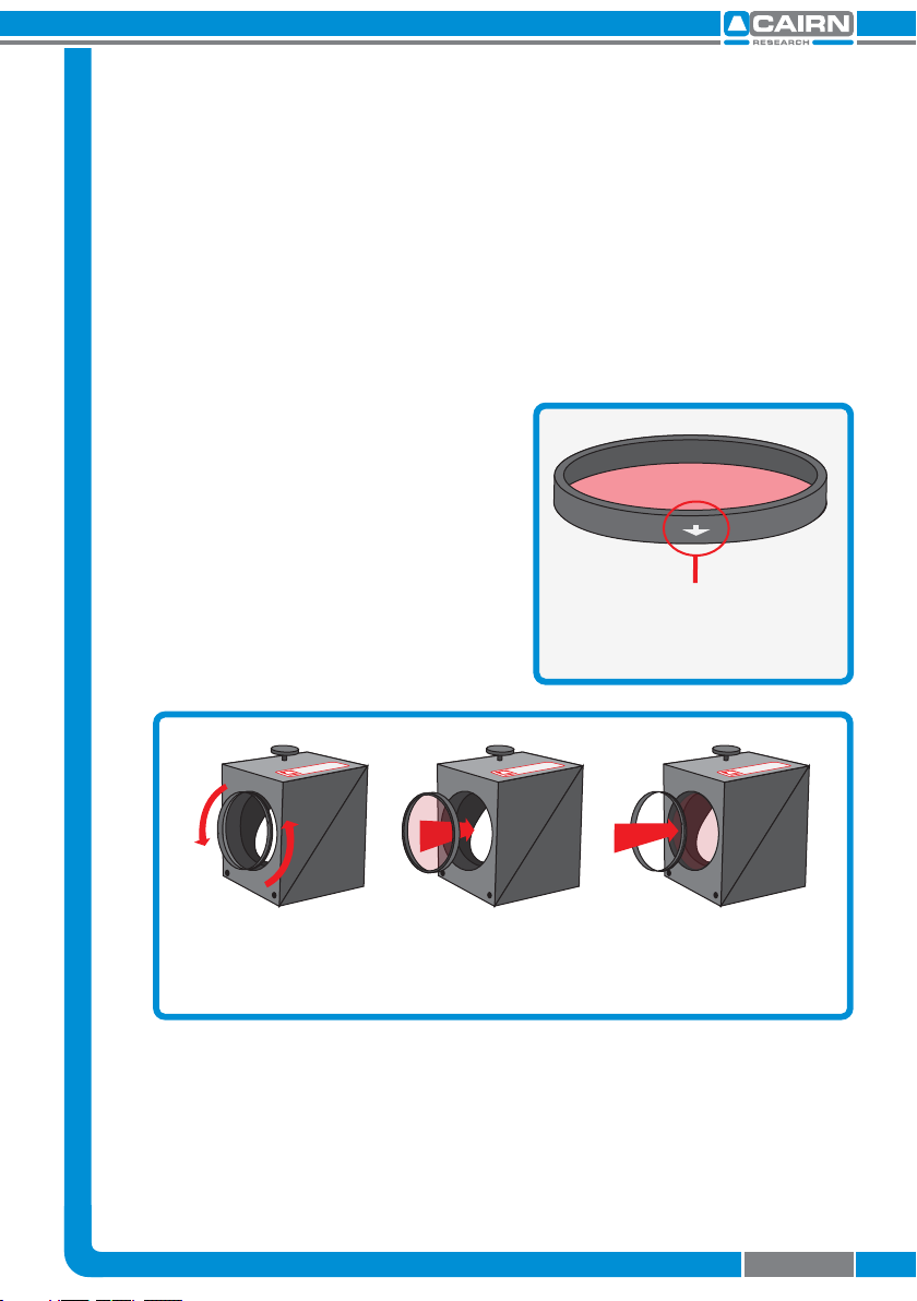
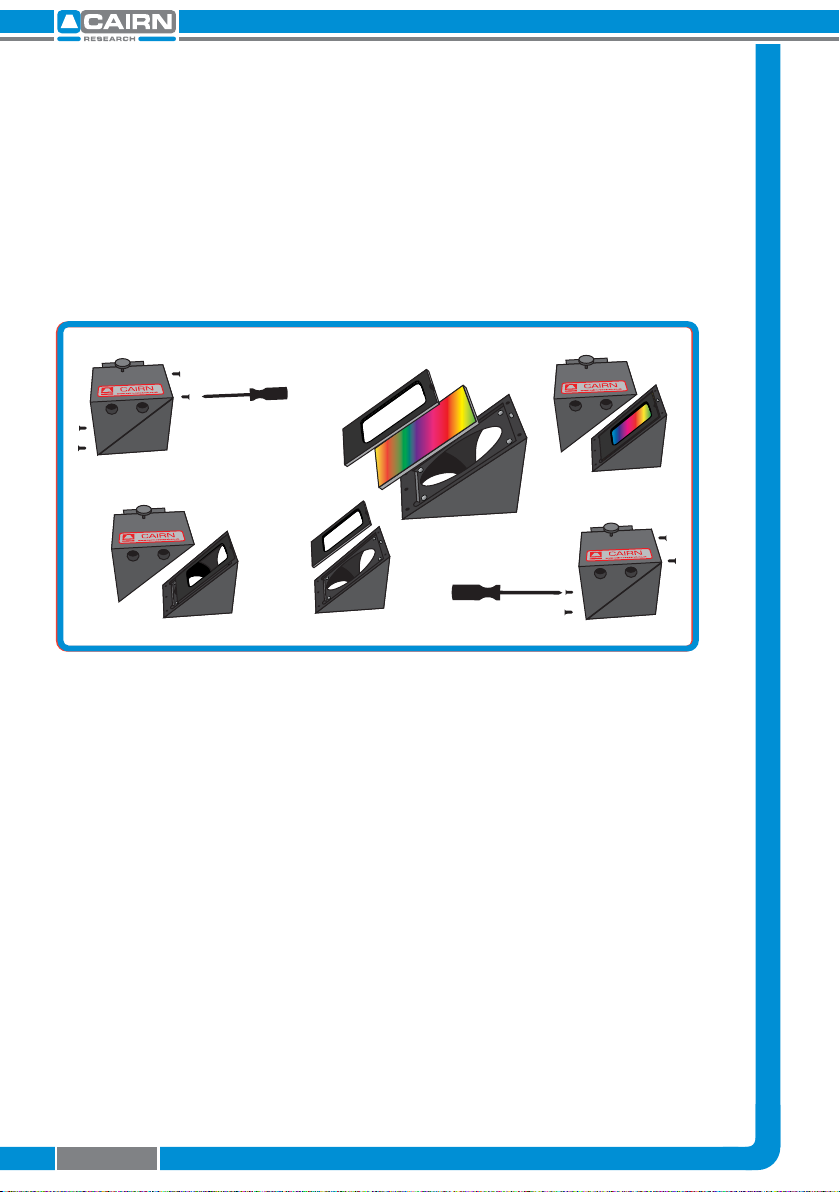
To control the relative intensity of the two
pathways, we recommend using neutral
density ltering in the brighter pathway
using the auxilliary component mounts.
This is required only when one image is
disproportionately brighter than the
other.
This auxilliary position can also be used for corrector lenses to reduce
chromatic abberation and ensure both pathways are focussed on the
camera sensor.
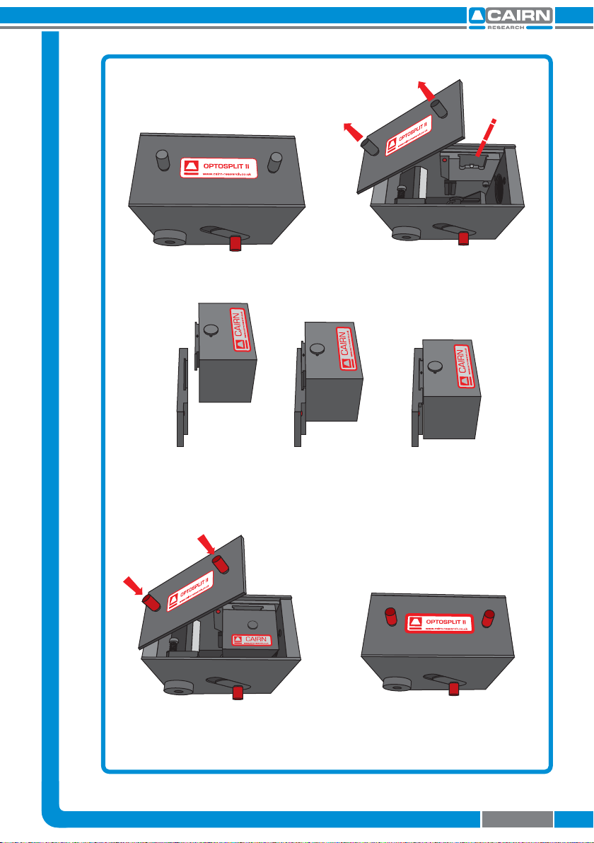
2.5 Installing the Optosplit II in the Light Path
Before installing the Optosplit II unit it is important to rst set up the
microscope, camera, and software to give a clear image of an object of
less than half the size the camera frame. Ideally this should be a real
sample with the appropriate optical properties for the installed lter
set. Failing this, a standard bright eld image can be used, but this may
lead to arbitrary intensity dierences between the spectrally resolved
images.
Firstly the CCD camera should be mounted on the
microscope C-mount output and the port adjusted
to give the sharpest possible image. Once a clear
image can be seen the camera should be switched
o and removed from the microscope.
The Optosplit II should then be tted on to the
microscope with the diaphragm
orientated toward the output of the
microscope. The camera can then be
xed onto the output port of the
Optosplit II, with the top orientated
so that the top of the camera lies
parallel with the top of the Optosplit
II. If you are tting onto a vertical
mount then the tops should still be
orientated in the same direction.*
V1
V2
H2
Auxilliary component mounts.
Top of camera
OPTOSPLIT II
www.cairn-research.co.uk
OPTOSPLIT II
www.cairn-research.co.uk
Page 5

* A 1mm nylon spacer is also included with each unit. This may be
required on the camera output mount, particularly when mounting a
shutter in addition to the OptoSplit.
Having tted the camera to the output port of the
Optosplit II it should be possible to adjust the image
to see a sharp picture of the aperture edges with the
sample in focus. The image should line up with the
edges of the aperture and should not have any
rotation or slant in either direction.
During manufacture the Optosplit II is calibrated
with the two images approximately super imposed,
so when it is rst installed a single central image is
seen on screen.
3 Operation of the Optosplit II
The Optosplit II uses a single control for adjusting image seperation
and allows for dierent sizes of samples to be used. There are
additional controls for rening the ROI, and centering the image.
V1
V2
H2
The image should
not have any slant.
Image.
Image.
Split adjuster
V2 adjuster
H2 adjuster
V1 adjuster
Aux. component
mounts
TRIM
Clamp Screw
Trim Controller
Split adjuster
Page 6

3.1 Adjusting and Locking the Aperture
The Optosplit II is supplied with an adjustable rectangular aperture
that allows the user to determine the ROI both vertically and
horizontally. Once the ROI has been dened, the aperture can be
locked in place using the aperture adjusters. (See diagram below.)
In order to adjust the ROI adjust each of the two levers on the input
port of the Optosplit II until the desired area is dened on the camera.
If you wish to lock the aperture in place then tighten the levers by
rotating them clockwise, and to loosen them rotate anti-clockwise.
3.2 Adjusting the Position of the Images
Once the camera is set up it is generally a good idea to familiarise
yourself with the operation of the alignment adjustments. Please note
that the diagrams overleaf indicate the images for a system using an
appropriately aligned and centred rectangular diaphragm. An image
similar to that shown opposite will be observed when the Optosplit II is
rst used, with the two images being displayed superimposed.
When the camera is mounted correctly, the split adjuster and the
aperture control are the only controls that will be frequently adjusted.
The remaining adjusters on the body of the Optosplit II should remain
untouched unless the lter set has become unaligned.
Aperture adjusters
Aperture
mechanism
Turn the aperture handles
clockwise to lock and unlock
the aperture adjusters
Page 7

Here we see the two superimposed
images. Although your image may be
monochromatic, colours have been
used here to dene the two images.
When the spectrally resolved images
are side by side on the camera chip
you are ready to record. When
carrying out experiments the
aperture should be set to mask the
region of interest tightly so that the
two images are located as closely as
possible on the camera chip.
Turning the Split control
anti-clockwise will seperate the two
images along the horizontal axis.
Only small adjustments will be
required when using the horizontal
image seperation adjustment.
Should the left and right images be
at dierent vertical heights then
adjust the images using the V1 and
V2 adjuster. Turning V1 will alter the
position of the shorter wavelength
image, and V2 will alter the position
of the longer wavelength image.
V1
V2
H2
Split adjuster
V1 adjuster
Page 8

3.3 Focussing the Camera on the Aperture
If the Optosplit II aperture is not in sharp focus, then adjust the ne
focus on the camera as follows:
1. Set an aperture size of less than half the width of the
camera frame.
2. Slacken the two hex screws that retain the output
rotating ring to allow the camera to rotate.
3. Separate the two images slightly with the Split control.
4. Slightly loosen the hex screws on the focussing ring.
Adjust the focus whilst ensuring the optosplit is
secure, and holding the camera, until the apertures
edges are in sharp focus.
5. Then lock o the focussing ring by re-tightening the
hex screws. Ensure the camera is again lined up with
its top orientated the same way as the top of the
Optosplit II and then lock o the output rotating ring.
6. Tighten the two hex screws that lock the camera
rotating ring.
V1
V2
H2
Hex screws
Split control
Focussing ring
Output
rotating
ring
Aperture levers
Page 9

3.4 Centering Images on the Camera
When the Optosplit II is initially installed, or if the lter block goes out
of alignment, the Optosplit II images can show visible aberrations, or in
extreme cases only a single image may be observable for any setting of
the separation control. In these cases the following procedure will
enable the lter set to be recongured.
1. Dene a small area using the Optosplit II aperture and
centre the shorter wavelength image horizontally
using the Split control.
2. Centre the same image vertically using the vertical
oset adjustment marked V1 on the Optosplit II body.
3. The short wavelength is now correctly positioned.
4. To centre the long wavelength pathway, we
superimpose the longer wavelength image on the
shorter wavelength image we have just centred.
Do this using the V2 and H2 adjusters.
5. Centre the image horizontally by smaller adjustments
of H2. Once the image is exactly superimposed on the
long wavelength image in the centre of the eld of
view we can adjust the vertical position of the image.
6. Adjust the vertical position with V2.
7. Recheck image horizontal alignment and repeat
steps 5 & 6 if required.
Note: If the images are superimposed o-centre then image
aberrations can result, so ensure the short wavelength image is
correctly centered before positioning the long wavelength image
Page 10

3.5 Image Optimisation
(Trim Adjustment)
Vignetting is when the image
appears darker towards one
edge. This eect can be easily
corrected by adjusting the trim
control. To adjust the trim
control, loosen the clamp screw
on the underside of the Optosplit
II by a quarter of a turn in order to
free the slider which controls the
trim control. Gently move the
slider until the vignetting is eliminated. If the slider is moved too far
then the vignetting will become apparent on the other image and will
need to be adjusted in the opposite direction until both images are the
same intensity. It is important to remember to re-tighten the clamp
screw once the adjustment is complete.
If the Optosplit II has been congured into single channel (non-split
mode) (see section 3.6) and Trim adjustment is required to compensate
for vignetting being observed, it is likely the slider will need to be at
the extreme of its range of movement to either end.
TRIM
Clamp Screw
Vignetting is a darkening of the image
towards one edge.
Trim Controller
Page 11

3.6 Single channel (non-split) mode
When dual splitting is not required, the OptoSplit II unit can be used in
bypass mode, allowing the unit to remain in situ on the microscope
whilst utilising the full camera chip to generate one image.
There are several ways this can be achieved:
A: Removing the lter cube
Suitable if no emission lters are required in the light path
1. Remove the dichroic mirror cube (see section 2.3)
2. Centre the image using the Split control
3. Open the aperture
4. Adjust the Trim control to remove any vignetting (see section
3.5)
B: Blocking the longer wavelength path
Suitable if only the shortest wavelength channel is required
1. Leave the dichroic mirror cube in place and block the long
wavelength path using the shutter plate provided. Most
dichroic mirror have long-pass characteristics, in which case
the longest wavelength will be the transmitted channel.
(See section 4 for help dierentiating the channels).
2. Centre the image using the Split control
3. Open the aperture
4. Adjust the Trim control to remove any vignetting
C: Blocking the shorter wavelength path
Suitable if only the longest wavelength channel is required
Follow the steps for option B, but block the short wavelength
path (reected channel) with the shutter plate instead.
Page 12

4 Technical Summary
The Optosplit II uses a conventional dichroic mirror to seperate the
light into two dierent spectral bands. This wavelength selection is
usually augmented by the use of bandpass lters as shown below.
The design is loosely based on technology described by Kinosita et al.
(J.Cell Biol. (1991) 115, 67-73), but includes several proprietary features,
most notably:
A rotating mirror cradle to give precise symmetrical control of
the degree of separation whilst maintaining identical path
lengths.
A half-size fully silvered mirror at the output port for
recombining the images.
Fine adjustment controls for camera focus and vertical
alignment.
Optional ROI denition using adjustabe rectangular aperture.
The system is supplied with high grade AR coated achromatic doublet
lenses and dielectrically coated mirrors for maximum throughput.
Dimensions excluding couplings. H55, W110, D110 (mm)
Dimensions including couplings. H55, W261, D110 (mm)
Approximate weight. 1.26 kg
Power consumption. 0
3.6 Single channel (non-split) mode
When dual splitting is not required, the OptoSplit II unit can be used in
bypass mode, allowing the unit to remain in situ on the microscope
whilst utilising the full camera chip to generate one image.
There are several ways this can be achieved:
A: Removing the lter cube
Suitable if no emission lters are required in the light path
1. Remove the dichroic mirror cube (see section 2.3)
2. Centre the image using the Split control
3. Open the aperture
4. Adjust the Trim control to remove any vignetting (see section
3.5)
B: Blocking the longer wavelength path
Suitable if only the shortest wavelength channel is required
1. Leave the dichroic mirror cube in place and block the long
wavelength path using the shutter plate provided. Most
dichroic mirror have long-pass characteristics, in which case
the longest wavelength will be the transmitted channel.
(See section 4 for help dierentiating the channels).
2. Centre the image using the Split control
3. Open the aperture
4. Adjust the Trim control to remove any vignetting
C: Blocking the shorter wavelength path
Suitable if only the longest wavelength channel is required
Follow the steps for option B, but block the short wavelength
path (reected channel) with the shutter plate instead.
Direction
of light
Reected image
Transmitted image
Split control
CCD Sensor
Aperture
Page 13

OPTOSPLIT II
www.cairn-research.co.uk
261mm
110mm
60mm
79mm
55mm
52mm
TRIM
121mm
261mm
110mm
60mm
110mm
52mm
Page 14

5 Technical Support
E-mail: [email protected]o.uk
Web: http://www.cairn-research.co.uk
Address: Cairn Research
Graveney Road
Faversham
Kent
ME13 8UP
Telephone: +44 (0) 1795590140
Fax: +44 (0) 1795594510
Page 15
Page 15
Other manuals for OptoSplit II
2
Table of contents