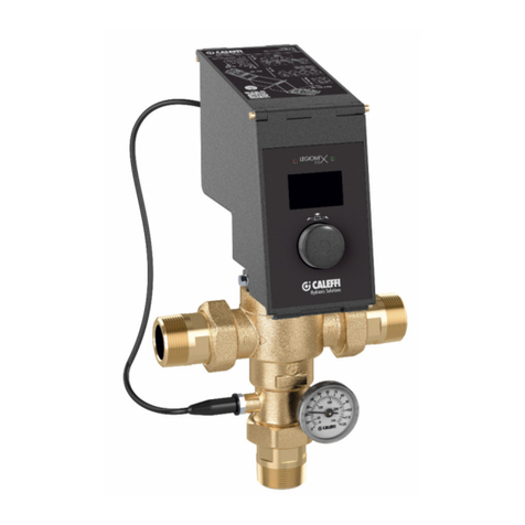
CALEFFI DeltaSol 268050 Guide

Circulation units
for solar thermal systems, with solar regulator DeltaSol® C+
28199
268-269 series
Function
Circulation units ar us d on th primary circuit of
solar th rmal syst ms to control th t mp ratur
in th hot wat r storag . Th pump insid th
units is activat d by th signal arriving from th
r gulator. Mor ov r, saf ty and functional d vic s
for optimum control of th circuit ar fitt d in th
units.
Th y ar availabl with flow and r turn conn ction
or with r turn conn ction only.
Som v rsions ar also compl t with th digital
r gulator D ltaSol®C+ for solar th rmal syst ms,
suitabl for th op ration and control of 9 diff r nt
typ s of solar th rmal syst ms.
1
INDEX
Function
Product range
Technical specifications
Characteristic components
Installation
Filling the system
Commissioning
1
2
3
4
5
6
Components 7
Application diagrams 8
INSTALLATION AND COMMISSIONING MANUAL

NOTICE
The followin instructions must be read and understood before installin , commissionin and
servicin the circulation unit.
Th saf ty symbol is us d in this manual to draw att ntion to th r sp ctiv saf ty instructions.
Th m aning of this symbol is as follows:
N.B! YOUR SAFETY IS INVOLVED. FAILURE IN FOLLOWING THESE INSTRUCTIONS MAY
RESULT IN INJURIES.
- Th circulation unit for solar th rmal syst ms must b install d by a qualifi d t chnician in complianc with
r l vant national and/or local r gulations.
- If th circulation unit is not install d, commission d and s rvic d corr ctly in accordanc with th instructions
giv n in this manual, it might not work prop rly and could put th us r in dang r.
- Mak sur that all conn ction fittings ar wat rtight.
- Wh n r alising hydraulic conn ctions, mak sur that thr ad d conn ctions ar not ov rstr ss d m chanically.
Ov r tim , xc ssiv str ss may caus br akag s with hydraulic l aks and damag to prop rty and/or p rsonal injury.
- Wat r t mp ratur s xc ding 50°C may caus s v r burns.
- Wh n installing, commissioning and s rvicing, tak th n c ssary pr cautions so that th s t mp ratur s will not
b hazardous for p opl .
CAUTION: Risk of electric shock. Remove the power supply before carryin out any work.
Failure in followin these instructions may result in personal injury or dama e to
property.
2
Product range
Cod 268050 Circulation unit with r turn conn ction 1–13 l/min siz 3/4”
Cod 269050 Circulation unit with flow and r turn conn ction 1–13 l/min siz 3/4”
Cod 268250 Circulation unit with r turn conn ction, with r gulator D ltaSol
®
C+ 1–13 l/min siz 3/4”
Cod 269250 Circulation uniti with flow and r turn conn ction, with r gulator D ltaSol
®
C+ 1–13 l/min siz 3/4”
Package content
Th packag contains:
Circulation units
• Th solar circulation unit compl t with front
and r ar insulation.
• Th wall fixing brack t.
Regulator (only for v rsions compl t with)
• Solar r gulator D ltaSol®C+.
• 4 t mp ratur prob s.
Accessories:
• Bag of 2 M5 scr ws, S6 scr w anchors and
wash rs.

3
Technical specifications
Materials
Shut-off valves
Body: brass EN 12165 CW617N
Ch ck valv : brass EN 12164 CW614N
T mp ratur gaug : st l / aluminium
Air se arator device
Body: brass EN 12165 CW617N
Instrument holder
Body: brass EN 12165 CW617N
S als: EPDM
O-Rings: EPDM
Flow meter
Body: brass EN 12165 CW617N
Transpar nt l v l gaug : PSU
Flow indicator: brass EN 12164 CW614N
Hydraulic s als: EPDM
Insulation
Mat rial: EPP
Av rag thickn ss: 30 mm
D nsity: 45 kg/m3
Working t mp ratur rang : -5
–
120°C
Th rmal conductivity: 0,037 W/(m·K) at 10°C
R action to fir (UL 94): class HBF
Performance
M dium: wat r, glycol solutions
Max. p rc ntag of glycol: 50%
Max. working t mp ratur :
- d a rator sid flow: 160°C
- pump sid r turn: 110°C
Max. working pr ssur : 10 bar
Saf ty r li f valv working t mp ratur rang : -30–160°C
Saf ty r li f valv s tting: 6 bar (for oth r s ttings, s 253 s ri s)
Ch ck valv min. op ning pr ssur (∆p): 2 kPa (200 mm w.g.)
Working t mp ratur rang of shut-off and ch ck valv : -30
–
160°C
Working t mp ratur rang of flow m t r : -10
–
110°C
Flow rat adjustm nt: 1–13 l/min
Flow rat indicator accuracy: ±10%
Pr ssur gaug scal : 0–10 bar
T mp ratur gaug scal : 0-160°C
Conn ctions: 3/4” F
Hos conn ction: 3/4” M
Fill/drain conn ctions: with Ø 15 mm hos conn ction
Grundfos Solar 15-65 um
Body: cast iron GG 15/20
El ctric supply: 230 V - 50 Hz
Max. pr ssur : 10 bar
Max. t mp ratur : 110°C
Prot ction class: IP 42
Digital regulator
El ctric supply: 230 V - 50 Hz
Nominal pow r consumption: 1,5 VA (12 V (ac))
4 Pt1000 prob inputs
2 r lay outputs with s miconductor with contact rating: 1 A
2 t mp ratur prob s with working rang : -50
–
200°C
Prob cabl working t mp ratur rang : -50
–
70°C
2 t mp ratur prob s with working rang : -50
–
200°C
Prob cabl working t mp ratur rang : -50
–
180°C
Ambi nt t mp ratur rang : 0
–
40°C
Prot ction class: IP 20
Dim nsions: 172 x 111 x 49 mm
Head available at the circulation unit connections
00
H (mm w.g.)
G (m3/h)
H (kPa)
0
1
2
3
UPS 15-65
6
5
4
3
2
1
60
50
40
30
20
10
0,2 0,4 0,6 0,8 1,0 1,2 1,4 00
H (mm w.g.)
G (m3/h)
H (kPa)
0
1
2
3
UPS 15-65
6
5
4
3
2
1
60
50
40
30
20
10
0,2 0,4 0,6 0,8 1,0 1,2 1,4
Power consum tion
0
P (W)
G (m3/h)
20
30
40
50
60
70
80
0,2 0,4 0,6 0,8 1,0 1,2 1,4
1
2
3
UPS 15-65
268 series Flow rat adjustm nt rang 1
–
13 l/min 269 series Flow rat adjustm nt rang 1
–
13 l/min

4
Characteristic components
1) Grundfos Solar 15-65 circulation pump
2)
Saf ty valv with adjustabl outl t typ 253 s ri s
3) Fill/drain cock with control k y
4) Instrum nt hold r fitting with pr ssur gaug
5) Flow m t r
6) D a rator with air v nt
7) Flow t mp ratur gaug
8) R turn t mp ratur gaug
9) Pr -form d sh ll insulation
10) Shut-off valv with built-in ch ck valv
11) Conn ction kit for xpansion v ss l (optional)
12)
Display with synoptic diagram and t mp ratur indication*
13) R gulating k ys*
14) T mp ratur prob *
15) Stainl ss st l prob pock t cod 257004 (optional)
16) Hos conn ction
* only for v rsions with D ltaSol®C+ r gulator
1
2
3
4
5
8
9
11
10
16
16
a
a
a
a
a
a
a
a
a
a
a
a
aaa
a
a
a
a
a
a
a
a
a
a
a
aa
a
a
a
a
a
a
a
a
a
a
aa
a
a
a
a
a
a
a
a
a
a
aaa
a
a
a
a
a
a
a
a
a
a
a
aa
0
20
40
60
80
100
120
140
160
c
o
n
f
o
r
m
e
n
o
r
m
e
I
S
P
E
S
L
0
2
46
8
10
bar
CL 2.5
1
13
11
9
7
5
3
l/min
10
a
a
a
a
a
a
a
a
a
a
a
a
aaa
a
a
a
a
a
a
a
a
a
a
a
a
a
a
a
a
a
a
a
a
a
a
a
aa
a
a
a
a
a
a
a
a
a
a
aaa
a
a
a
a
a
a
aa
a
a
a
aaa
a
a
a
a
a
a
aa
a
aa
a
a
a
a
a
a
a
a
a
a
a
a
a
a
a
a
a
a
a
a
a
0
20
40
60
80
100
120
140
160 0
20
40
60
80
100
120
140
160
c
o
n
f
o
r
m
e
n
o
r
m
e
I
S
P
E
S
L
0
2
46
8
10
bar
CL 2.5
7
9
16
16
1
13
11
9
7
5
3
l/min
1
2
3
4
11
5
8
6
12
13
75°65°
12°
14
15

5
Installation
• Fix th wall support brack t, using th fixing scr ws suppli d in th pack (1).
• Ins rt th r ar insulation, through th notch provid d (2).
• Ins rt th unit compon nts in th insulation using th sp cial notch s mad in th brack t and th slots in th compon nts. Block th
compon nts on th brack t, pulling th m downwards to that th y click into th ir housing (3).
• Establish th position for installing th xpansion v ss l at a distanc allow d by th l ngth of th fl xibl pip , using th brack t provid d.
Th latt r allows th us of xpansion v ss ls with a maximum capacity of 24 l, s th instructions conc rning th acc ssori s (4).
• Install th pip s of th whol syst m and conn ct th solar unit. S cur th compon nts and th pip s to th r ar insulation.
Fully tight n all th fittings.
• Th unit’s thr ad d fittings ar tight n d and t st d in th ass mbly phas at th factory. How v r, wh n commissioning it is n c ssary to
ch ck th s al of th fittings, p rforming a pr ssur t st.
• Mak th l ctrical conn ctions of th syst m, as sp cifi d in th r gulator instruction manual. Apply th front part of th insulation.
Fillin the system
• Op n th shut-off valv coupl d with th automatic air v nt, install d in th high st point of th solar th rmal syst m (1).
• Op n th shut-off and ch ck valv s, turning th control st ms (2) through 45° (do not r mov th t mp ratur gaug s).
• Fill by m ans of a pump, using th cock (A) locat d at th low st point of th syst m, until air no long r com s out of th air v nt (1). If th
solar th rmal syst m is mad using wat r pr mix d with antifr z , any top-ups must b carri d out using a mixtur with th sam
proportions.
• Clos th shut-off valv of th air v nt (3).
• Clos th cock (A).
a
a
a
a
a
a
a
a
a
a
a
a
aaa
a
a
a
a
a
a
a
a
a
a
a
aa
a
a
a
a
a
a
a
0
20
40
60
80
100
120
140
160 0
20
40
60
80
100
120
140
160
c
o
n
f
o
r
m
e
n
o
r
m
e
I
S
P
E
S
L
0
2
46
8
10
bar
CL2.5
A
1
13
11
9
7
5
3
l/min
1234
12
3

Commissioning
• Clos th flow m t r fil/drain cock (1) and incr as th syst m pr ssur up to th maximum d sign pr ssur , by m ans of th xt rnal filling
pump appli d to th fill/drain cock of th saf ty unit.
Wh n this pr ssur is r ach d (2), clos th fill/drain cock of th saf ty unit using th cap
quipp d with control k y.
• Op n th valv s of th unit (3) and switch on th pump of th solar circulation unit (do not r mov th t mp ratur gaug s).
• L t th wat r circulat for a c rtain tim , th n ch ck th wat r tightn ss.
• Op n th air v nt again, install d in th high st point of th solar th rmal syst m, r p ating th d a ration phas , bri fly activating th
circulation pump.
• R stor th d sir d working pr ssur with th filling pump.
• Th syst m flow rat may b chang d by m ans of th flow m t r (4). This modulation is p rform d by th ball valv with which it is
quipp d (s r sp ctiv charact ristics). To r gulat /limit th flow rat it is r comm nd d to follow th indications of th solar pan l
manufactur r.
• Aft r th first op rating hours, th solar th rmal syst m must b d a rat d again, both in th high st point and on th air s parator (on th
v rsions wh r this is cont mplat d).
Onc d a ration has b n compl t d, ch ck th syst m pr ssur and if n c ssary r stor to th d sir d working pr ssur .
Draining the s stem
• Th draining op ration is n c ssary if th syst m has b n fill d only with wat r and th r is a risk of frost.
• Op n th shut-off and ch ck valv s, turning th ball valv through 45°. Op n th air v nts in th high st point.
• Op n th drain cock at th low st point of th syst m.
Flushing the s stem
•
Clos th flow m t r r gulating ball valv (1). Th n op n th fill/drain cock, by turning it count r-clockwis using th cap with control k y (2).
• By m ans of a (s parat ) xt rnal pump appli d on th fill/drain cock of th saf ty unit (3), l t th m dium flow through th solar pan ls and
th h at xchang circuit until th m dium com s out of th fill/drain cock (4) of th flow m t r.
• Bri fly op n th flow m t r ball valv (4) to xp l all th air from th syst m.
• L av th xt rnal pump running on th syst m for a f w minut s to nsur corr ct flushing.
a
a
a
a
a
a
a
a
a
a
a
a
aaa
a
a
a
a
a
a
a
a
a
a
a
aa
a
a
a
a
a
a
a
0
20
40
60
80
100
120
140
160 0
20
40
60
80
100
120
140
160
c
o
n
f
o
r
m
e
n
o
r
m
e
I
S
P
E
S
L
0
2
46
8
10
bar
CL2.5
1
13
11
9
7
5
3
l/min
12
34
1234
6

Shut-off and check valves
Th shut-off valv s ar quipp d with a built-in ch ck valv ,
position d insid th ball.
1. To allow th passag of th fluid
in both dir ctions, th ball valv s
must b op n d at 45°, using a
9 mm fix d wr nch.
Th ch ck valv is op n d by th
ball, s figur (A).
2. In normal syst m op ration, th
ball valv s must b compl t ly
op n.
Air separator device
Th solar circulation units with flow and r turn conn ction ar
quipp d with an air s parator d vic on th flow lin . Th gas s
s parat d from th th rmal carri r m dium coll ct at th top of th
d a rator.
Th coll ct d gas s must b vacuat d from tim to tim ( v ry
day aft r commissioning and aft rwards, d p nding on th
quantity of air, onc a w k or onc a month) using th manual air
v nt with a suitably siz d scr wdriv r.
To maintain optimal ffici ncy of th solar th rmal syst m,
aft rwards, it is n c ssary to
v nt th syst m v ry six
months by using th d a rator.
A
Full closing and opening of the valve
Th valv can b
compl t ly op n d or
clos d.
A slot on th obturator
st m indicat s th
status of th valv .
Correction for liquids with different density
Th variation in th flow rat r ading r mains within th rang of
accuracy indicat d (±10%), for glycol p rc ntag s up to 50%.
Fully closed
Fully o en
7
Captiv nut
Flow rat adjustm nt
Fitting 1/2” F
Graduation
Fitting 3/4” F
Flow meter
Th flow m t r is a floating gaug flow rat m asurator with a
built-in r gulating ball valv .
It works within th rang of 1–13 l/min.
The flow meter must be fitted in a vertical osition only.
A th rmom tric lab l is plac d on th back of th flow m t r to
signal if th maximum p rmitt d t mp ratur (110°C) has b n
xc d d:
whit color = t mp ratur not xc d d;
dark color = maximum t mp ratur xc d d.
Th lab l r moval mak s th manifactur r warranty on th d vic
xpir .
Th l v l is tak n from th
top dg of th float.
N.B! Us only a
9mm fix d
wr nch to r gulat th flow
m t r.
13
11
9
7
➜
➜
open closed
2
3
0
°
F
1
1
0
°
C
Thermometric
label
AB

Application diagrams
Shut-off valve
Pump
Air vent
Expansion vessel
Temperature gauge
Safety relief valve
Automatic
filling
2
0
20
40
60
80
100
120
140
160 0
20
40
60
80
100
120
140
160
c
o
n
f
o
r
m
e
n
o
r
m
e
I
S
P
E
S
L
0
2
46
8
10
bar
CL2.5
a
a
a
a
a
a
a
a
a
a
a
a
aaa
a
a
a
0
20
40
60
80
100
120
140
160
c
o
n
f
o
r
m
e
n
o
r
m
e
I
S
P
E
S
L
0
2
46
8
10
bar
CL2.5
c
o
n
f
o
r
m
e
n
o
r
m
e
I
S
P
E
S
L
0
2
46
8
10
bar
CL2.5
a
a
a
a
a
a
a
a
a
a
a
a
aaa
a
a
a
0
20
40
60
80
100
120
140
160
c
o
n
f
o
r
m
e
n
o
r
m
e
I
S
P
E
S
L
0
2
46
8
10
bar
CL2.5
c
o
n
f
o
r
m
e
n
o
r
m
e
I
S
P
E
S
L
0
2
46
8
10
bar
CL2.5
1
13
11
9
7
5
3
l/min
1
13
11
9
7
5
3
l/min
1
13
11
9
7
5
3
l/min
a
a
a
a
a
a
Shut-off valve
Pump
Air vent
Expansion vessel
Temperature gauge
Safety relief valve
Automatic
filling
2
a
a
a
a
a
a
a
a
a
a
a
a
aaa
a
a
a
a
a
a
a
a
a
a
a
aa
a
a
0
20
40
60
80
100
120
140
160 0
20
40
60
80
100
120
140
160
c
o
n
f
o
r
m
e
n
o
r
m
e
I
S
P
E
S
L
0
2
46
8
10
bar
CL2.5
0
20
40
60
80
100
120
140
160
c
o
n
f
o
r
m
e
n
o
r
m
e
I
S
P
E
S
L
0
2
46
8
10
bar
CL2.5
c
o
n
f
o
r
m
e
n
o
r
m
e
I
S
P
E
S
L
0
2
46
8
10
bar
CL2.5
0
20
40
60
80
100
120
140
160
c
o
n
f
o
r
m
e
n
o
r
m
e
I
S
P
E
S
L
0
2
46
8
10
bar
CL2.5
c
o
n
f
o
r
m
e
n
o
r
m
e
I
S
P
E
S
L
0
2
46
8
10
bar
CL2.5
1
13
11
9
7
5
3
l/min
1
13
11
9
7
5
3
l/min
1
13
11
9
7
5
3
l/min
a
a
a
a
a
a
a
a
a
8
This manual suits for next models
5
Table of contents
Other CALEFFI Water Pump manuals
Popular Water Pump manuals by other brands

Sealey
Sealey TP6807 quick start guide

Franklin Electric
Franklin Electric MH Series Operating and maintenance manual

Intex
Intex Krystal Clear 604 owner's manual

Grundfos
Grundfos Hydro Multi-B Installation and operating instructions

PIAB
PIAB piPUMP 23 manual

Steinbach
Steinbach CPS Series instruction manual

Pfeiffer Vacuum
Pfeiffer Vacuum UniDry 050-P Service instructions

Pfeiffer Vacuum
Pfeiffer Vacuum OKTA 500 G operating instructions

Waterite
Waterite VELO-FLO Installation and owner's manual

Tuthill
Tuthill KLRC40 Operator's manual

Becker
Becker U 4.630 operating instructions

Grundfos
Grundfos UPMM instructions