manuals.online logo
Brands
  1. Home
  2. •
  3. Brands
  4. •
  5. Calibre
  6. •
  7. Radar Detector
  8. •
  9. Calibre DL/H User manual

Calibre DL/H User manual

Warning LED(s)
1. Consult with vehicle owner about LED location. For best visibili-
ty, choose a mounting location as close to the vehicle gauges
as possible.
2. Check for proper clearance behind the area where the LED(s)
will be installed (approximately 1”) and drill a 3/16” hole in the
chosen location for the LED(s). CALIBRE
DL/H
models require
the mounting of a second LED for rear radar warnings.
3. Route all of the LED wires under the dash per DIAGRAM A1.
FRONT
ALERT REAR
ALERT
GREY LED WIRE GREY LED WIRE
The included CALIBRE Remote Control is used to allow the driver to adjust settings on the
CALIBRE and to mute audio alerts during prolonged encounters. It may be mounted virtually
anywhere inside the vehicle with the included double stick tape or remain unmounted.
DIAGRAM A1
&
Warning Pod(s)
1. Consult with vehicle owner about Pod location. For best visibility,
choose a mounting location as close to the vehicle gauges as
possible.
2. Before mounting the Warning Pod(s), clean both the Pod surface
and desired mounting location on the dash with isopropyl alcohol.
3. Position the Warning Pod(s) on the dash with the provided double
stick “O” ring tape. CALIBRE
DL-P/H
models require the mount-
ing of a second Pod for rear radar warnings.
4. Route the black cable(s) from the Warning Pod(s) through or under
the dash per DIAGRAM B1. DIAGRAM B1
FRONT
WARNING POD REAR
WARNING POD
WHITE
GREY
BLUE
GREY
&
1. Remove the under dash
panel and mount the Interior
Network Module using the
supplied cable ties to the
existing factory wire looms,
brackets, or other support
structures as per DIAGRAM
C1. The Interior Network
Module can be mounted
horizontally or vertically
under the dash.
2. Connect the LED, ignition-
on, and ground wires per the
separate enclosed block
diagram sheet. HORIZONTAL MOUNT VERTICAL MOUNT
INTERIOR NETWORK
MODULE
WIRE TIE
WIRE TIES
WIRE TIE
DIAGRAM C1
INTERIOR NETWORK
MODULE
Interior Network Module
WHITE LED
WIRE
BLUE LED
WIRE
“O” RING
TAPE
“O” RING
TAPE
DL/SL HARDWIRE SERIES
Installation Instructions
& Recommended Procedures
Amplified Speaker
1. Route the amplified speaker cable around a panel
edge and reattach the under dash panel per
DIAGRAM D1.
2. For maximum audio output and concealment,
mount the amplified speaker to the outside of the
under dash panel with the supplied screws per
DIAGRAM D1.
DIAGRAM D1
DASH PANEL
SPEAKER
SCREWS
SPEAKER
CABLE
If the vehicle is not equipped with an under
dash panel (e.g., Porsche), mount the ampli-
fied speaker to existing factory wire looms,
brackets, or support structures with the
supplied cable ties.
NOTE:
FRONT RADAR RECEIVER
(ALL MODELS)
All radar receivers can be mounted behind plastic, rubber, or fiberglass up to 1/4” thick. Do
not mount receivers behind metal, carbon fiber, or chromed plastic.
NOTE:
1. Choose a mounting location in the front of the vehicle that is not obstructed by any metal, carbon fiber, or
chromed plastic. The radar receiver must be mounted horizontally with the arrows pointing forward, towards
the road ahead.
2. Mount the radar receiver to the vehicle's structure using the supplied screws or wire tires (see diagram E1).
3. Connect the radar receiver to the 10’ black radar receiver cable. Align slot on cable plug to the notch on
radar receiver socket, slide the locking ring forward over the socket, and turn ring clockwise 1/4 turn to
engage safety lock (see diagram E2).
4. Route and affix the radar receiver cable along the inner fender in the engine compartment to the firewall
using the provided wire straps.
5. Route the radar receiver cable through a factory rubber grommet on the firewall and into the passenger
compartment (see diagram E3). Connect wires according to the separately enclosed block wiring diagram.
DIAGRAM E1
DIAGRAM E2 DIAGRAM E3
RADAR
RECEIVER
SELF-
TAPPING
SCREWS
FACTORY
GROMMET
FRONT
RADAR
RECEIVER
CABLE
WHITE
GREEN
BROWN
LOCKING RIB
LOCKING
WINDOW
LOCKING
PIN
LOCKING
RING
KEY
GUIDE KEY WAY
LOCKING
PIN
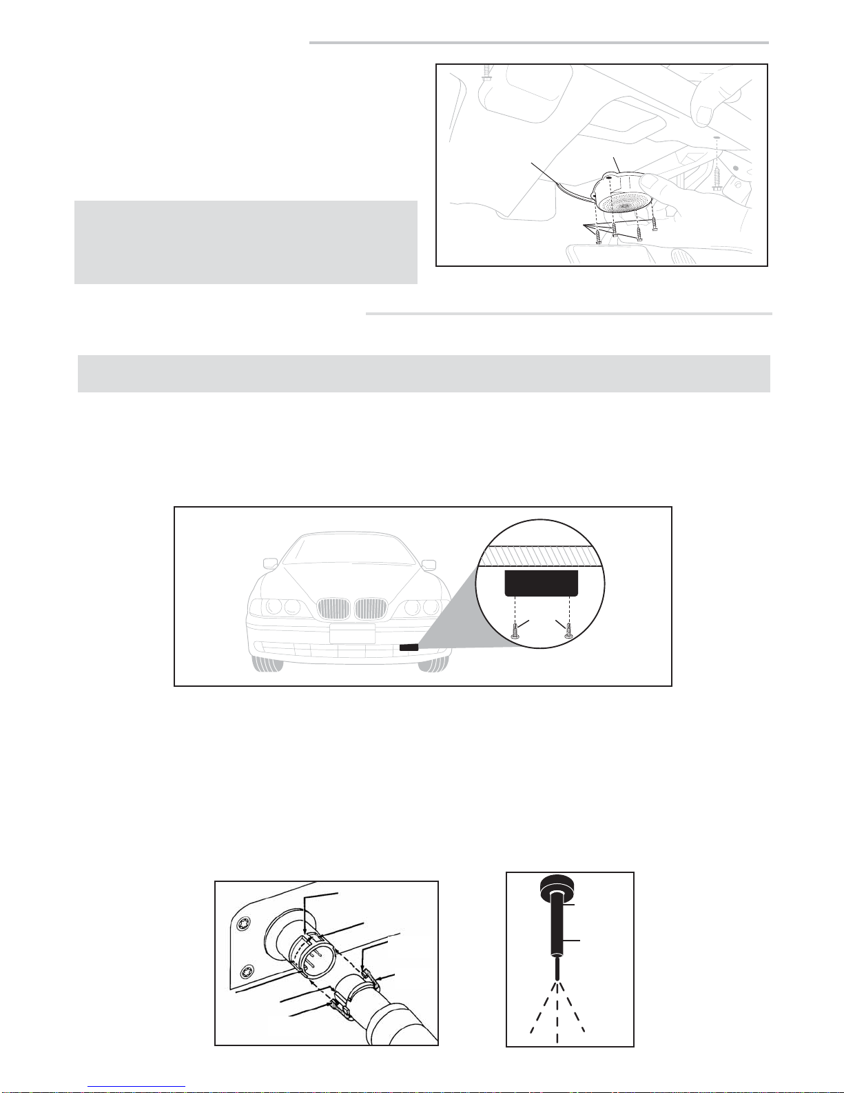
1. Choose a mounting location in the rear of the vehicle that is not
obstructed by any metal, carbon fiber, or chromed plastic. The
radar receiver must be mounted horizontally with the arrows
pointing to the rear, towards the road behind the vehicle.
2. Mount the radar receiver to the vehicle's structure using the
supplied screws or wire tires (see diagram F1).
3. Connect the radar receiver to the 25’ black radar receiver cable.
Align slot on cable plug to the notch on radar receiver socket,
slide the locking ring forward over the socket, and turn ring clock-
wise 1/4 turn to engage safety lock (see diagram F2).
4. Route the rear radar receiver cable into the trunk through a
factory grommet.
5. If a factory grommet is not available, use the provided strain relief:
a. Choose a location in the trunk compartment as close to the
radar receiver as possible.
b. Drill a 1/2” hole into the chosen location for the strain relief.
c. Install the strain relief and tighten the mounting nut securely
(see diagram F3)
d. Route the rear radar receiver cable through the strain relief,
leaving a little slack in the receiver cable.
e. Tighten the waterproof gasket nut to create a water proof seal.
6. Route the rear radar receiver cable through the trunk, into the
passenger compartment along the driver's side, and under the
dash. Connect wires according separately enclosed block
wiring diagram.
All radar receivers can be mounted behind plastic, rubber, or fiberglass up to 1/4” thick. Do not
mount behind metal, carbon fiber, or chromed plastic.
NOTE:
METAL
SUPPORT
SCREWS
REAR RADAR RECEIVER
(BEHIND BUMPER COVER)
RECEIVER
DIAGRAM F1
DIAGRAM F2
DIAGRAM F3
ROUTE THROUGH VEHICLE
MOUNTING NUT
METAL
TRUNK
WATERPROOF
GASKET MATERIAL
TO RADAR DETECTOR
Do not drill into the trunk until you know
what is on both sides of the drilling area.
Watch for cables, spare tires, and gas tank.
CAUTION!
LOCKING RIB
LOCKING
WINDOW
LOCKING
PIN
LOCKING
RING
KEY
GUIDE KEY WAY
LOCKING
PIN
44702 08/10
REAR RADAR RECEIVER
(ALL MODELS)

This manual suits for next models

3

Other Calibre Radar Detector manuals

Calibre Calibre DL User manual

Calibre

Calibre Calibre DL User manual

Calibre K40 User manual

Calibre

Calibre K40 User manual

Calibre Calibre DL User manual

Calibre

Calibre Calibre DL User manual

Popular Radar Detector manuals by other brands

Cobra Pro 9680 Important information

Cobra

Cobra Pro 9680 Important information

Whistler Z-11R+ user manual

Whistler

Whistler Z-11R+ user manual

Neoline X-COP 9000 user manual

Neoline

Neoline X-COP 9000 user manual

Cobra XRS 9500 operating instructions

Cobra

Cobra XRS 9500 operating instructions

Radiodetection RD8100 user guide

Radiodetection

Radiodetection RD8100 user guide

Escort Solo S3 owner's manual

Escort

Escort Solo S3 owner's manual

Whistler XTR-130 owner's manual

Whistler

Whistler XTR-130 owner's manual

RIDGID NaviTrack II quick start guide

RIDGID

RIDGID NaviTrack II quick start guide

Radio Shack 22-1695 owner's manual

Radio Shack

Radio Shack 22-1695 owner's manual

Whistler 948 owner's manual

Whistler

Whistler 948 owner's manual

Blinder M27 X-TREME user manual

Blinder

Blinder M27 X-TREME user manual

Whistler 1640 owner's manual

Whistler

Whistler 1640 owner's manual

Uniden DFR9 Detailed user's manual

Uniden

Uniden DFR9 Detailed user's manual

Snooper Evolution Plus user manual

Snooper

Snooper Evolution Plus user manual

Cobra XRS 9345 operating instructions

Cobra

Cobra XRS 9345 operating instructions

Cobra XRS 9970G operating instructions

Cobra

Cobra XRS 9970G operating instructions

Whistler XTR-220 owner's manual

Whistler

Whistler XTR-220 owner's manual

Cobra SLR 600 operating instructions

Cobra

Cobra SLR 600 operating instructions

manuals.online logo
manuals.online logoBrands
  • About & Mission
  • Contact us
  • Privacy Policy
  • Terms and Conditions

Copyright 2025 Manuals.Online. All Rights Reserved.