California Instruments P Series Installation guide

PGUI or PGUI32
TRAINING MANUAL
P Series, RP Series
Graphical User Interface
Software
1251RP Programmable AC Source
Revision: 1.1
Date: June 24, 1998

PGUI / PGUI32 Training Manual
21.1

PGUI / PGUI32 Training Manual
1.1 3
Table of Contents
1. Introduction.......................................................................................................................................................5
1.1 Program Purpose.........................................................................................................................................5
1.2 Training Manual Purpose............................................................................................................................5
1.3 Requirements...............................................................................................................................................6
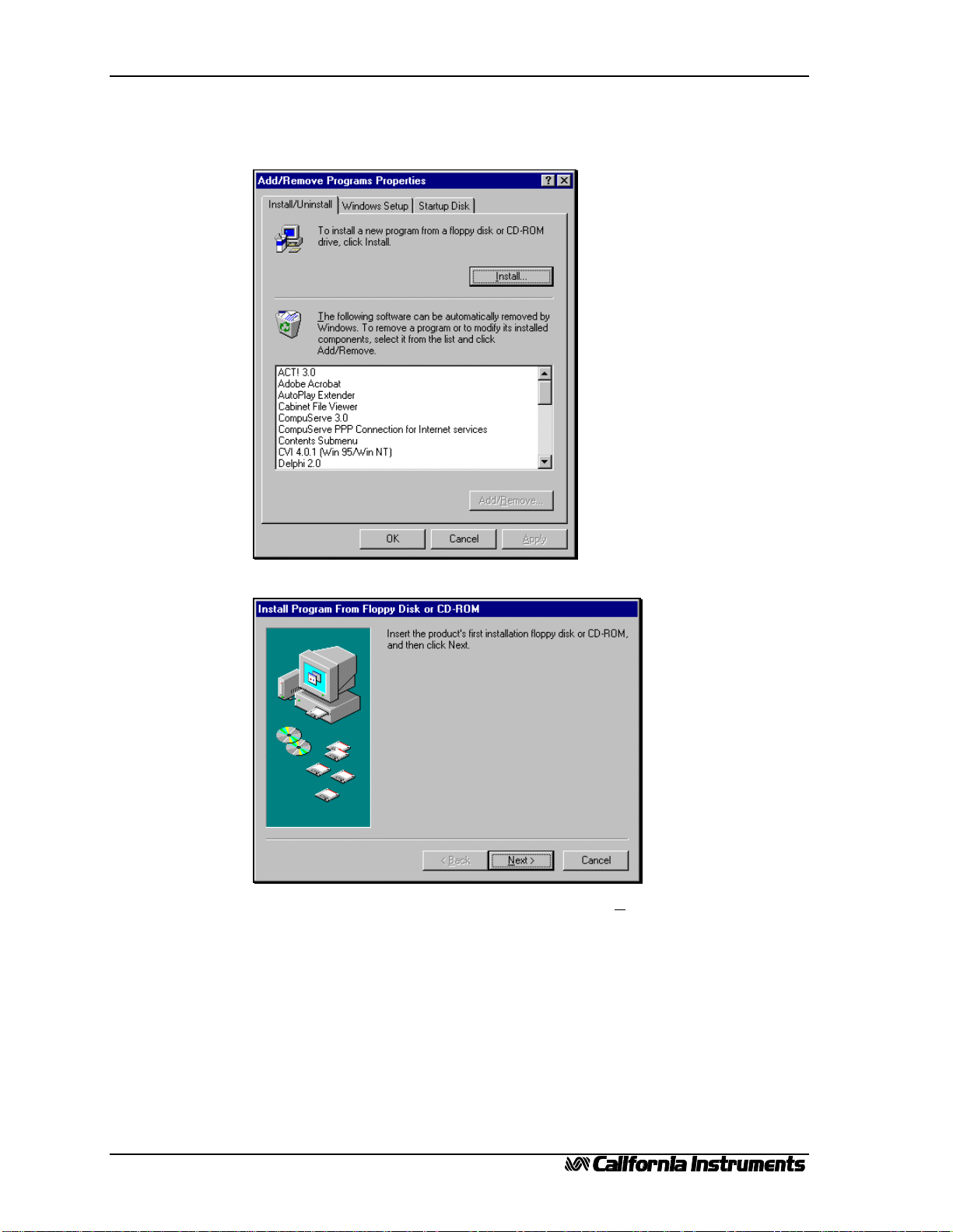
2. PGUI Installation ..............................................................................................................................................9
2.1 Windows 95Installation procedure...........................................................................................................9
2.2 Windows 3.1Installation procedure........................................................................................................13
3. PGUI Main Window.......................................................................................................................................15
3.1 Steady State Control..................................................................................................................................16
3.2 Front Panel Lock.......................................................................................................................................17
3.3 Status Bar..................................................................................................................................................17
3.4 Command Menu........................................................................................................................................18
3.5 Toolbar......................................................................................................................................................18
3.6 Next...........................................................................................................................................................18
4. System Menu...................................................................................................................................................19
4.1 Interface ....................................................................................................................................................19
4.2 Configuration Settings...............................................................................................................................21
4.3 Power-On Settings.....................................................................................................................................22
5. Measurements .................................................................................................................................................23
5.1 Enable and Disable Measurements............................................................................................................23
5.2 Recording Measurement Data to disk. ......................................................................................................24
6. Transient Programming...................................................................................................................................27
6.1 Voltage Transients ....................................................................................................................................27
6.2 Frequency Transients ................................................................................................................................29
6.3 Voltage and Frequency Transient..............................................................................................................30
6.4 Data Entry Mode Options .........................................................................................................................31
6.5 Saving Transient programs........................................................................................................................32
7. AC Source Setup Files ....................................................................................................................................33
7.1 Saving front panel setups ..........................................................................................................................33
7.2 Recalling front panel setups......................................................................................................................34
8. Conclusion ......................................................................................................................................................35

PGUI / PGUI32 Training Manual
41.1

PGUI / PGUI32 Training Manual
1.1 5
1.
Introduction
This training manual was designed to help a new user of California Instruments‘ P or RP Series AC
power sources become familiar with the operation of the PGUI / PGUI32 Graphical User Interface
software. This program is included with the interface option for this product line.
To work through this training manual, it may be useful to have an actual AC source connected to the
PC. This is not required however as the PGUI / PGUI32 will operate in simulation mode in the
absence of a connection to an AC source. In the remainder of this training manual, the term PGUI will
be used to denote both the PGUI (16 bit) and the PGUI32 (32 bit) version of this program.
1.1 Program Purpose
The PGUI can be used to control all aspects of the AC power source over the IEEE-488 bus (RP
Series only) or RS232C (all models). This allows full PC control without the need to use the front
panel of the instrument. The PGUI automatically adjusts to the connected AC Source configuration.
The PGUI is NOT a replacement for a custom Automated Test program that requires the use of
multiple IEEE-488 or VXI based instruments. This program only operates a single AC source and will
ignore all other types of instruments connected to the same bus. It is possible however for other
Windows programs to run at the same time as the PGUI and control other instruments. If your
application requires an integrated test program involving multiple instruments from different vendors,
we suggest you consider developing your own software. Instrument drivers for National Instruments
LabView are available free of charge from California Instruments to support this effort.
1.2 Training Manual Purpose
This training manual serves as an introduction to the use of the PGUI program. It does not replace
the on line help system included in the PGUI program. Not all aspects of the program’s operation are
covered in this training manual.
You can work through this manual at your own pace by following the steps and examples used to
point out the operation of various program aspects. It is important to have the program installed and
available while working through this manual. The presence of an AC source is not required however.
First time users of the PGUI that need to control the AC source from a PC may find it useful to work
through this training manual first. If you have not used the PGUI for a while and need to get back to it
for a new project or requirement, you may also benefit from working through this manual as a
refresher.

PGUI / PGUI32 Training Manual
61.1
1.3 Requirements
In order to use the PGUI program, you will need the following hardware and software items. You
will also have to install the PGUI software and any IEEE-488 interface driver software on your PC if
you have an RP model and intend to use the IEEE-488 interface. All units can be operated over
RS232C using an available PC com port.
•PC running Windows 3.1 or Windows for Workgroups 3.11.
The PGUI is a 16 bit Windows program and will not operate under Windows NTor any other true
32 bit operating system. The PC you plan to use should have enough CPU processing power and
memory (DRAM) to run any of the Windows versions listed above. We recommend at least a 486
class PC with 8 Mbytes of RAM. The PGUI will run on 386 class PC’s with as little as 4 Mbytes of
RAM but performance will be less than satisfactory.
•PC running Windows 95/98™or Windows NT™.
The 16 bit version, PGUI, will operate under Windows 95/98as well. A 32 bit version of this
program is available as well - PGUI32 - and is recommended for users of Windows 95/98. Users of
Windows NT have to use the 32 bit PGUI32. The 16 bit program will not run under NT.
•PC Based IEEE-488 Interface Controller.
RP Series AC sources can be controlled remotely using either the IEEE-488 General Purpose
Instrumentation Bus (GPIB) or an RS232C serial interface.
For IEEE-488 control, you will need to install a suitable National Instruments IEEE controller in
your PC. Other vendor IEEE controller cards have not been tested with the PGUI and may not
function.
One of the following IEEE controller cards is recommended:
National Instruments
•GPIB-PCII/IIA
•AT-GPIB/TNT
•PCMCIA-GPIB
Follow the manufacturer’s instruction for card installation. Make sure to install both the hardware
(controller card) and any software that is supplied with the card. If you do not, you will only be able to
use the PGUI program in its simulation mode.
•PGUI Program.
Make sure you have the latest version of the PGUI for Windows. If not, some of the features
covered in this training manual may not be available to you. You can check your version by selecting
the Help About menu which will show you the program’s release number. The latest version is
available from California Instruments’ website at www.calinst.com. This manual was created using
PGUI version 2.12 / PGUI32 version 1.00.

PGUI / PGUI32 Training Manual
1.1 7
Figure 2Version information PGUI 16 bit
•Supported AC Sources.
Supported models are :
P Series RP Series
1001P 801RP
1251P 1251RP
2001RP
(PGUI32 only)
If you do not have one of these units connected to your PC or have a suitable interface in your PC
yet, you can still proceed with this training session as the PGUI program will operate fully in
simulation mode.
Figure 1Version information PGUI32 32 bit

PGUI / PGUI32 Training Manual
81.1

PGUI / PGUI32 Training Manual
1.1 9
2.
PGUI Installation
This section covers installation of the AC source control software under Window 95. If you are
using Windows 3.1or Windows for Workgroups 3.11, the installation procedure is very similar
except you use the Program Manager’s File, Run menu to start the SETUP program located on the
installation disk.
2.1 Windows 95 Installation procedure
To install the AC source control software under Windows 95, proceed as follows:
1. From the Start menu, select Settings.
1. From the Settings options, select Control Panel
2. In the control panel folder, locate the Add/Remove Programs icon

PGUI / PGUI32 Training Manual
10 1.1
3. Double click on the Add/Remove Programs icon to launch the Windows 95
Add/Remove Programs property dialog.
4. Click on the Install button located in the top right corner of this dialog box.
5. Insert the first installation disk in drive A and click on the Next button at the bottom of
the dialog box.

PGUI / PGUI32 Training Manual
1.1 11
6. The program will locate the SETUP.EXE program on the first distribution disk and ask
for confirmation.
7. Click on Finish to start the installation process.
8. The setup program will now run and display a dialog box that shows the default directory
for the AC source control software which is PGUI on the current drive. At this time you
can accept the default directory by clicking on the OK button or enter a different
directory. If the directory you enter does not already exist, it will be created.
9. The setup program will now run and display a some information on the supported
products and interfaces. If you do not want to install the program at this time, cancel the
setup program by clicking on the Cancel button.

PGUI / PGUI32 Training Manual
12 1.1
10. If you do want to install the program, click on Install System. A dialog box will appear
next that shows the default directory for the AC Source Control software which is PGUI
on the current drive. At this time you can accept the default directory by clicking on the
OK button or enter a different directory. If the directory you enter does not already exist,
it will be created.
11. The setup program will create a program group. The default group name used will be
PGUI. You may also elect to store the AC source control program icon in a different
group.
You may also elect not to add a program icon and group for the AC source control
software. In this case, you will have to start the program from the Windows command
line or a shortcut for it in the Start menu later.
12. Once you click on OK, the install program will proceed to expand and copy all program
and support files to the relevant directories. During this phase, a progress box will be
displayed.

PGUI / PGUI32 Training Manual
1.1 13
13. Upon completion of the installation process, a message appears instructing you to
register your software with California Instruments. Since products are often shipped to a
company address with no reference to the end-user, California Instruments may not have
your exact address or email address. By registering both the AC source control software,
you will be automatically notified of software upgrades.
14. You can now remove the PGUI installation disk.
In Windows 95, the installation program will create a Start menu program group called PGUI and
a program shortcut also called PGUI.
We recommend you keep the distribution disk in a safe place in case you ever need to re-install the
AC source control software.
2.2 Windows 3.1 Installation procedure
The installation under Windows 3.1or Windows for Workgroups 3.11is very similar to the one
for Windows 95. Instead of using the Control Panel, use the Windows 3.1File Manager to run the
setup program located on the distribution disk. In Windows 3.1, the installation program will create a
windows group called PGUI in the Program manager.
See section 2.1 for further instructions.

PGUI / PGUI32 Training Manual
14 1.1

PGUI / PGUI32 Training Manual
1.1 15
3.
PGUI Main Window
The PGUI program is started by double clicking on the PGUI icon under Windows 3.1or selecting
the PGUI program from the Windows 95Start Menu, Programs. Each time the program is started, it
will try to connect to the AC Source if it was connected at the time the program was closed. If not or if
the AC source cannot be found at the same IEEE address or serial port, the PGUI will launch in
simulation mode.
This chapter will familiarize you with the information displayed on the Main program window. The
main window is primarily used to control the steady state output of the AC Source. It also contains all
the menus, the status bar and the toolbar.

PGUI / PGUI32 Training Manual
16 1.1
3.1 Steady State Control
The main window provides a virtual front panel used to control the AC source from the PC. It has
controls for all steady state parameters.
1. Use the Frequency slider to change the frequency between it lowest and
highest value.
2. Position the cursor in the Frequency text box and enter a value that is
greater than the maximum allowed frequency of 500 Hz, for example, type in
800 and press the Enter key. Notice that the value send to the AC Source is 500
Hz which is the upper Limit value. Using this direct data entry method is
sometimes faster and more precise than using the slider control.
3. Notice the operation of the slider controls. There are three ways of operating
them:
3.1. By dragging the slider handle. This sweeps the frequency up or down
in increments that are a function of the speed at which you drag the slider
handle.
3.2. By clicking on the arrows located at the left or right end of the control.
This changes the frequency at 0.1 Hz increments.
3.3. By clicking between the slider handle and the left or right end of the
control. This changes the frequency by 1 Hz at a time.
Note that the PGUI32 uses a different slider control. The operation of it
however is very similar to the one described above.
Set the frequency back to 50.0 Hz.
4. Select the High voltage range. Notice the change in current limit. If this
value was set to its maximum, it will be reduced by a factor of two.
5. Set the voltage range back to Low range and notice that the current limit
value does not change. The PGUI can only ensure you do not exceed hardware
limits of the unit. It does not make a decision on changing user set values other
than that.
6. Switch back to High voltage range and set the voltage to 230 Vrms.
7. Set the current limit to maximum.
8. Finally, close the output relay to apply power to the Unit Under Test.

PGUI / PGUI32 Training Manual
1.1 17
9. The Steady State control panel should now look as shown below.
The Steady State control panel is always available and all other functions of the program can be
accessed from its menu to tool bar.
3.2 Front Panel Lock
The front panel lock check box located in the lower left corner of the Main window is only useful
when an AC source is connected to the PC. In this case, this check box allows you to toggle the unit
between LOCAL and REMOTE modes. It is always recommend to put the AC source in REMOTE
mode when using the PGUI program. This locks the front panel and prevents any one from interfering
with the AC Source’s operation.
The LOCAL mode can be used to release the unit for front panel access. There
are situations in which it may be necessary to use the front panel.
3.3 Status Bar
PGUI status bar - Program and interface status
PGUI32 status bar - Program, error and interface status. Includes date and time readouts.
The status bar is always located at the bottom of the Main window and displays important
information about the condition of the program and the AC source. It also contains a field that displays
the connection method to the AC source as either IEEE-488, RS232C or Simulation. If you are in
simulation mode, all functions of the selected AC source can be simulated.
NOTE: Make sure you are not in simulation mode when you have a unit connected as the program
will appear to be working normally but in reality, you are in simulation mode. If you do not have a unit
connected, you can only work in simulation mode.

PGUI / PGUI32 Training Manual
18 1.1
3.4 Command Menu
The command menu contains all the menus available for the PGUI program. From these menu’s,
you can access all other screens in the PGUI. We will cover the individual menus and their purpose in
the next chapter. For now, suffice it to say you will be using these menu’s frequently.
3.5 Toolbar
A Toolbar is a set of iconized short cuts that allow you to access sub menu’s with a single mouse
click. As you get more familiar with operating the PGUI, you may rely on the Toolbar more and more
as it gets you to the right screen faster. Each Toolbar button has a yellow tooltip that will popup when
you leave the cursor on an icon for more than a second. This tooltip indicates the function of the
Toolbar button your mouse is on.
3.6 Next
This concludes this brief tour of the Main window. Note that this window mainly serves to control
the steady state output of the AC source. In the next chapter we will start exploring some of the
available menus that access more advanced features of the AC source.

PGUI / PGUI32 Training Manual
1.1 19
4.
System Menu
The System menu provides access to some key screens that allow you to configure the PGUI to
work the way you want. This relates in particular to the interface settings when you have an AC source
connected.
4.1 Interface
The Interface dialog is an important screen as it allows you to set the interface parameters to the AC
Source. If these settings are incorrect, you will not be able to successfully use the PGUI program. The
same screen also allows you to select the Simulation mode if you do not have an AC Source connected
to the PC.
Finally, the Interface window also contains an interactive command line which allows you to send
SCPI commands to the AC Source and read back responses to queries. This command line has a drop
down list which contains commonly used SCPI commands so you do not have to memorize their
syntax.
Exercise: 1. Pull down the System menu and select the Interface... sub menu or click on
the IEEE connector symbol in the Toolbar. This will bring up the Interface
window.
2. If you are operating in Simulation mode already, the interface window will
be small and will only show alternative interface types such as IEEE-488 or
RS232C. To display the full size Interface window, you have to select either
IEEE-488 or RS232C.
3. Click on the RS232C option and observe the COM port and baud rate
selections that appear. The bottom portion displays the command line. Note
that no other COM parameters can be set. The serial format is fixed to 1 start
bit, 8 data bits and one stop bit for all P and RP Series instruments.
4. Click on the IEEE-488 Bus option to select the IEEE interface. The Interface
window will now allow you to select the Bus address for the AC Source. If you
have a source connected on either interface, you can click on “Verify
Connection” to establish the connection. This will report the model number
and serial number of the unit found at the specified address or com port.

PGUI / PGUI32 Training Manual
20 1.1
5. The PGUI32 will automatically scan all COM ports when RS232 is selected
or all IEEE addresses when IEEE-488 is selected, looking for a supported AC
source. If found, the com port number or IEEE-488 address will be set for the
user. The 16 bit PGUI does not automatically scan all ports so the user will
have to pre-select the correct port or IEEE-488 address. If the IEEE address or
COM port settings are incorrect, you will not be able to communicate with the
AC source and an error message will appear. Note that the P Series does not
offer an IEEE-488 interface so you have to use RS232C. The RP Series offers
both interfaces.
6. If you have a unit connected, use the Send Command pull down box to send
commands to the AC Source and observe the response to any queries in the
Receive box at the bottom.
7. Once you have established the connection or selected Simulation mode, click
on Close to confirm your settings.
The remainder of this training manual will assume you are in simulation mode. You can continue to
use the actual source connected through IEEE or RS232C if you wish. Most exercises will operate
largely the same.
This manual suits for next models
5
Table of contents