Calorex AW550 Service manual

Page 1 SD092750 ISSUE 34
Please read these instructions carefully as they will enable
you to get maximum efficiency and reliability from your new
Calorex Heat Pump.
This manual should be left with the user of the machine
after installation/commissioning.
HEALTH & SAFETY WARNING
As the Heat Pump embodies electrical and rotational equipment it is recommended that ONLY competent
persons carry out any work on this type of machine (see warranty conditions)
Contents
General Introduction ............................................................................................................................. 2
Installation ............................................................................................................................................. 3
1. Siting .................................................................................................................................................. 3
2. Ducting ............................................................................................................................................... 3
3. Plumbing ........................................................................................................................................... 6
4.0 Electrolytic corrosion in swimming pools ....................................................................................... 9
4.1 Electrical ........................................................................................................................................ 10
Controls and Indication Lamps ........................................................................................................... 20
Variheat Commissioning ..................................................................................................................... 21
Heat Pump Malfunction ....................................................................................................................... 22
User Check List .................................................................................................................................... 22
Datasheet ............................................................................................................................................. 23
Installation Drawings........................................................................................................................... 26
Installation Instructions MODELS R.C.U. 100/200/300 for use with Variheats with A/C feature ......... 28
LPHW fitted to 500/800/1200 ................................................................................................................ 30
Optional Indoor Control Panel ............................................................................................................ 32
Optional Inlet Duct Flanges and/or Filters ......................................................................................... 33
Warranty Conditions ............................................................................................................................ 35
Machine Record Log ........................................................................................................................... 36
Regular Planned Maintenance ........................................................................................................... 37
Owner/Installation Manual
Variheat Models
(AW550/800/1200/1400/1800/4000)
SD092750 iss 34
28/09/12


Page 3 SD092750 ISSUE 34
Installation
1. Siting
2. Ducting
See Figs. 2, 3, 4, and 5.
a) Ensure heat pump on site is as ordered,
i.e. model electrical supply and factory
fitted options.
b) Inspect unit for damage, in paticular inspect
the evaporator (finned side) to ensure that it is
undamaged (minor indentations in the fins do
not affect performance). If severely damaged
endorse delivery note in presence of the driver
and send a recorded delivery letter to the
transport company giving details.
c) Protect the unit if installation is delayed.
d) Provide a firm level base capable of supporting
operational weight of unit. Spread load if on timber
floor.
e) Ensure water cannot collect under the unit. It
is recommended that units are installed on
plinths 100mm above finished floor level and
also to aid condensate drainage.
f) Allow adequate clearance to service panels on
unit; recommend 500mm minimum (see
installation drawings).
g) All Calorex heat pumps are designed to be as
quiet as practicable, however, due
consideration should be given to siting in order
to fully exploit this feature, i.e. orientate inlet/
outlet parallel to occupied premises.
h) Ensure loose debris will not block air filters or
grilles.
IMPORTANT
As Variheat units are handling air at Pool Hall
temperatures, they must be sited in a warm
environment, i.e. pool hall, or insulated plenum. They
must not be sited in cold areas, i.e subject to
ambient air.
The quantity of air flow handled by each Variheat
unit is given on the data sheet together with
the maximum pressure available from
the fan to overcome total ducting resistance to air
flow, i.e. inlet, discharge ducting, grilles, and where
installed, air heater batteries.
It is recommended that a reputable duct work
company is associated with the duct design/
manufacture and selection of grilles for the total
system.
Note:
1. The humidity sensing tube situated by the air inlet
is to be encompassed by or extended to any inlet air
ducting. Refer to installation drawings.
2. All units have discharge ducting spigots as
standard.
3. Inlet ducting spigots are available from stockists.
4. Final connections to Variheat spigots must be
made of flexible ducting (rubber or canvas) to
eliminate transmission of vibration down the duct.
5. Before any discharge ducting is attached remove
plate (if fitted) from machine outlet or fan grille.
6. After completion of installation including all grilles,
ductwork etc., ensure that the air flow through the
machine is as specified in the data sheet ±10%. If
air flow is high, damp outlet to obtain correct airflow.
If airflow is low or high the unit will not function
correctly.
But discharge from each unit must be kept separate and
must not be incorporated into one common duct system,
unless non return dampers are used for each machine.
Minimum Free Air m²
Model Inlet
AW/AC 550/800VH 0,35
AW/AC 1200VH 0,45
AW/AC 1400/1800VH 0,56
AW/AC 4000VH 1,1
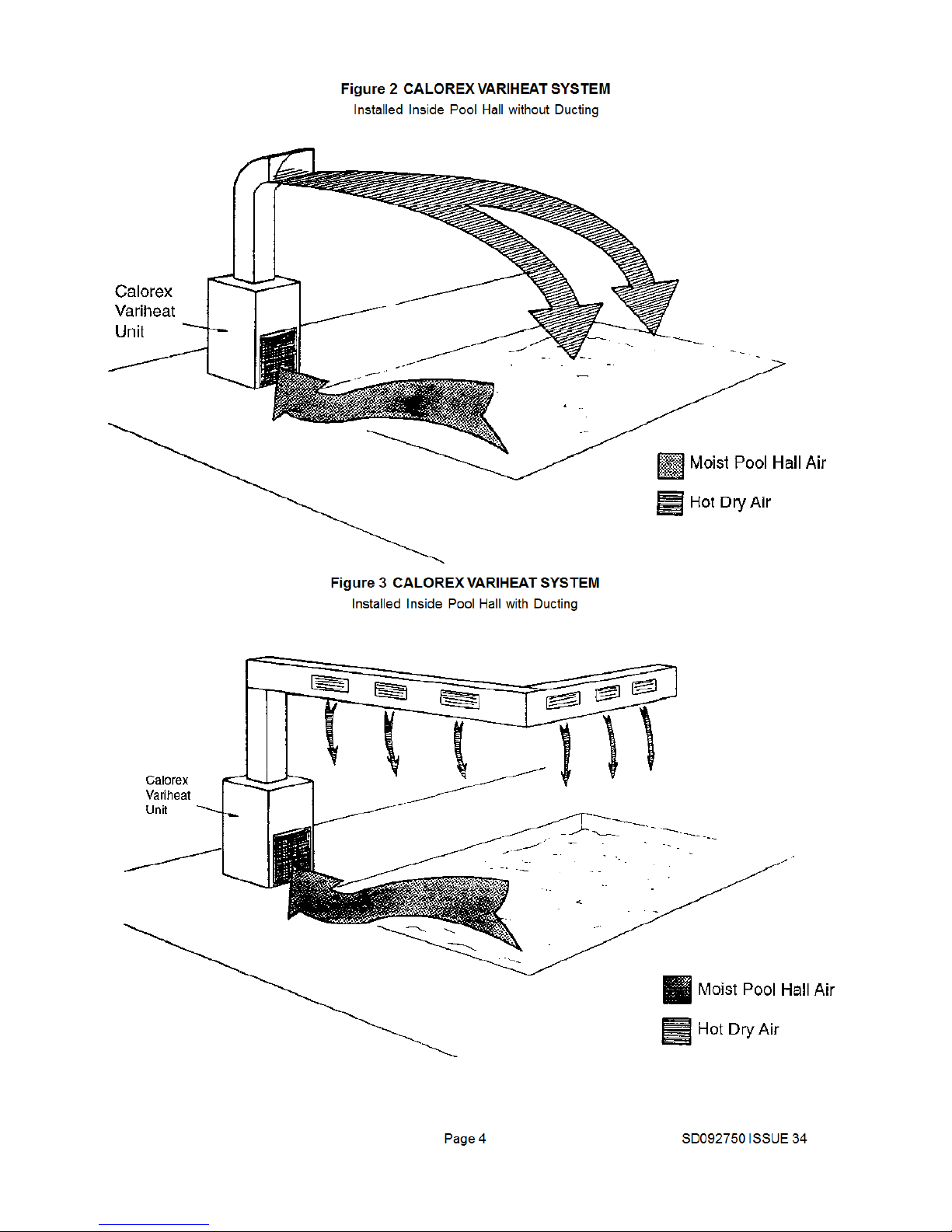
In order that moisture can be removed and
humidity control can be effected within the pool
hall, it is essential that correct air movement and
distribution is achieved.
The Variheat unit must extract the humid air
generated at pool surface and discharge the drier
air to areas which are subject tio condensation
problems (windows etc and, or comfort zones,
spectators, sitting out areas.
This can generally only be achieved by use of
ducting and correct application of grilles/ louvres
to effect air distribution and movement to these
areas.
NOTE: Variheat unit and ducting will be at pool
hall temperature and will require insulation if
exposed to lower air temperatures.
Exhaust from Pool Hall - Humid Air
Should be taken as low as practicable to inlet of
Variheat unit. In many instances siting of Variheat
unit in hall or changing rooms can eliminate use
of duct work to inlet. If duct work is to be fitted, an
inlet duct should be ordered from Calorex
distributer.
Inlet to Pool Hall- Dry Air
Generally achieved by overhead ducting with
suitable grilles to give balance and direction of air
flow. Consideration must be given to duct position
in relation to pool surface, material and finishes
so as not to promote maintenance problems.
Table 1
Required free areas to provide airflow to and from
heat pumps when installed in and enclosed area or
where required to pass air through a wall etc.
Free area is the available area through which air can
pass through a grille or louvres.
Note: If multiple units are installed in an enclosed
area then the inlet free areas required for each unit
can be added together to form one inlet aperture.


Page 6 SD092750 ISSUE 34
3. Plumbing
a) The Calorex Variheat Heat Pump must be
connected after the filter in the return pipe to the
pool. If an existing heater is being retained, then
the Calorex unit should be connected between
the filter and the other heater, see figure 6.
b) Calorex heat pumps have water inlet/oulet
connections as follows:
Models 550,800,1200 1½” BSP parallel, female.
Models 1400, 1800 & 4000 1½” BSP parallel,
male.
c) Suitable breakable couplings should be
installed local to heat pump.
d) If heat pump installed at lower level than pool
water then isolation valves should be fitted.
e) Drain valve or plug should be fitted to lower to
facilitate completedrain down in winter period.
f) Connections on all models from 550 to 1200 are
by parallel male fittings sealed by 'O' ring or
silicone mastic these should be hand tightened
only, otherwise damage may result to the
threads.
Note: Do not route pipes across service panels or
Air In/Outlet
g) The heat exchanger in the Heat Pump will, on
small pools, take the full flow rate of the
recirculating system (see Figure 6). On larger
pools a by-pass or separate auxiliary pump
may be necessary. (bypass 1½ hp or larger
water pumps) see Figures 7 and 8.
h) The condensate drain at the base of the unit
collects the condensation from the evaporator
fins. It is therefore necessary to ensure
that the Calorex is placed on a level plinth so
that the condensate water can run away and not
overflow the edges of the drip-tray inside the
machine.
Models 550,800,1200
drain connection to waste via 22mm push fit
domestic waste system.
Models 1400, 1800 and 4000
drain connection to waste via ¾2 & 1½” BSPM
stubs respectively.
N.B Hose must be a watertight fit.
i) When the pipework installation is complete the
pool pump should be switched on and the
system tested for leaks. Also check the filter
gauge to see that there is not an excessive
increase in back pressure. If everything is then
working normally the water circulating system is
ready to use.
j) Water circuit to and from unit to be capable of
maintaining within specified limits the rate of flow
required by heat pump (see data sheet).
k) All pipework must be adequately supported with
allowance for expansion/ contraction especially with
plastic pipework.
I) It is recommended that when installing water system
the last connections to be made in the system
should be the breakable connections to avoid any
stresses on to the unit connections.
m)To ensure efficient operation of the Heat Pump, an
adequate constant flow of water is required through
the condenser.
This is normally achieved by ensuring that the filter
pump is always operating at the same time as the
Heat Pump but this requires consumption of electricity
which would not normally be used during the filter ‘off
cycle’ period.
To reduce energy consumption the installation of a two
speed or small auxillary water pump (by-passing the
filter) should be considered. This method should only
be used on heavily used pools (4 hours turnover or
less to reduce the risk of overheating due to main
pump heat input.
The circuit can be incorporated in the initial installation
or added to an existing standard circuit.
IMPORTANT
1) The Calorex unit must never be connected in such a
way that the Heat Pump can be switched on without
adequate water flow through the condenser.
Integral interlock terminals provided on all models
(see figure 9).
2) All Pool Purifying Devices and Chemical Injection
Systems to be fitted down stream of heat pump with a
non return valve to prevent concentrated chemicals
back feeding into the heat exchanger. The practice of
dosing chemicals direct into Skimmer Basket, which
results in concentrated corrosive liquids passing over
vulnerable metal components must not be allowed.
3) Water quality must be maintained not only related to
solids, etc, but also pH between 7,4 ±0,4 and, if pool
water is saline at maximum concentration of 6% wt/wt.
4) Maximum pressure of water in heat pump circuit id
3kg/cm².
(140psi) 1400, 1800,4000 models.


Page 10 SD092750 ISSUE 34
To be in accordance with I.E.E. standards latest issue
or local codes of practice, also EMC 2006/108/EC.
Protected supply to incorporate fuses or motor rated
circuit breakers to specified rating, (see Data Sheet).
H.R.C. fuses are recommended. An isolator must be
fitted within 2m and in sight of the machine.†
All units must be correctly earthed/grounded. An earth
leakage trip of the current operating type is
recommended to be fitted to all pool electrics.
Inconsistent Electrical Supply
The following limits of operation must noy be
exceeded if Calorex machines are to be guaranteed
either in performance or warranty terms.
N.B This voltage must be available at the heat pump
whilst running.
† Note the Isolator must have a minimum of 3mm air
gap when turned off.
Voltage Minimum Maximum
Single Phase Machines (U.K) 207V 253V
Three Phase machines (U.K) 360V 440V
Single Phase Machines (60Hz) 187 253
Three Phase machines (60Hz) 187 253
Cycle Frequency 50Hz 47.5Hz 52.5Hz
Cycle Frequency 60Hz 57.0Hz 63.0Hz
INTERLOCK
All units have interlock circuits incorporated in control
circuit brought out to two terminals. These terminals are
shorted out for factory testing.
On site the shorting loop should be removed and two
wires taken to pair of voltage free contacts in water pump
starter/contactor/relay so that Heat Pump cannot operate
unless water pump is operating (see page 18 fig 9).
Note
1200 and 4000 three phase machines are fitted with a
phase rotation relay and will not run if the phases are not
connected in the correct order (phase sequence) or if the
supply voltage is 15% less than the nominal voltage.
(415V for 3~N 50Hz) . The lamp on the phase rotation
relay, situated in the electric box, is illuminated when the
phases are correctly connected and the voltage is
sufficient. The undervoltage protection feature is not
present in phase protection relays fitted in 3~ 60Hz
machines.
4.1 Electrical
(MACHINE WIRING AND SUPPLY)

Page 11 SD092750 ISSUE 34
Locations of Machine Supply Terminal Blocks
1 2 3 4 5 6 7
L1
L2
L3
NPool Pump
Interlock
Flow Switch
or
Soft Start
Pool Pump
Interlock
Flow Switch
or
Soft Start
Soft
Start
Remove Front
Service Panel
(¼ turn fasteners)
14/1800
Mains Terminal and
Earthing Point
(also External Interlock)
see Fig 9
Mains
Supply
In
4000
Mains Terminal and
Earthing Point
(also External Interlock)
see Fig 9
L1
L2
L3
N
1 2 3 4 5 6 7 8 9
AW/AC1400,1800,4000
AW/AC550,800,1200
MAINS IN TERMINAL
BLOCK AND
EARTHING POINT
MAINS
SUPPLY IN
REMOVE
SERVICE
PANEL
(1/4 TURN
FASTENERS)

Page 12 SD092750 ISSUE 34
DELAY
TIMER
LP
SWITCH
CONTROL
FUSE
FAULT LAMP
MAINS
LAMP RUN
CAP
INTERLOCK TERMINALS
LIVE
NEUTRAL
CONTACTOR
SOFT START THERMAL
OVERLOAD & FAULT
LAMP IF FITTED
RELAY/HARD
START CAP
IF FITTED
DEFROST
STAT
DEFROST
LAMP
HP
SWITCH
POOL STAT
POOL PUMP
STARTER OR FLOW
SWITCH
COMPRESSOR
C
S
R
SOFT START
IF FITTED
SOLENOID COIL
FAN MOTOR FAN
CAP
HUMIDISTAT
N/O CLOSES ON
WATER TEMP RISE
L2L1
COMPRESSOR
DELAY
TIMER
HP
SWITCH
FAN FUSE
FAULT
LAMP
MAINS LAMP
INTERLOCK
TERMINALS
FAN
MOTOR
L3 NEUTRAL
CONTACTOR
SOFT START
THERMAL
OVERLOAD
& FAULT
LAMP
DEFROST
STAT'
DEFROST
LAMP
IF FITTED
LP
SWITCH
POOL
STAT
POOL PUMP
STARTER
OR FLOW
SWITCH
SOLENOID
VALVE
FAN
CAP
HUMIDISTAT
CONTACTOR
O/LOAD
SOFT START (IF
FITTED)
L1
L2
L3
11
14
CONTROL FUSES
PHASE
ROTATION
RELAY
N/O CLOSES ON
WATER TEMP RISE
N/O CLOSES ON
WATER TEMP RISE
L2L1
COMPRESSOR
DELAY
TIMER
LP
SWITCH
CONTROL FUSE
FAULT
LAMP
MAINS LAMP
INTERLOCK
TERMINALS
FAN MOTOR
L3 NEUTRAL
CONTACTOR
SOFT START
THERMAL
OVERLOAD
& FAULT
LAMP
DEFROST
STAT'
DEFROST
LAMP
IF FITTED
HP
SWITCH
POOL STAT
POOL PUMP
STARTER
OR
FLOW
SWITCH
SOLENOID VALVE
FAN CAP
HUMIDISTAT
MODEL
550BVH
550BVHF
800BVHF
560BVHF
FUSE
5A
10A
10A
7A
FUSE RATINGS
800BVH 7A
860BVHF 7A
ELECTRICAL CIRCUIT DIAGRAM
AW 550/800 BVH THREE PHASE (3 ~ 50Hz)
ELECTRICAL CIRCUIT DIAGRAM
AW 550/800/1200 AVH SINGLE PHASE (1 ~ N 50Hz)
ELECTRICAL CIRCUIT DIAGRAM
AW 1200 BVH THREE PHASE (3 ~ 50Hz)

Page 13 SD092750 ISSUE 34
FUSE SIZES
TMBLK No. 10 11,12,13 14,15,16
FUSE 3A 3A 16A
MACHINE
OVERLOAD SETTING
1400
1800
COMPRESSOR FAN FAN BRHF
7.6A
9.2A
1.4A
1.4A
1.5A
1.5A
N/O CLOSES ON
WATER TEMP RISE
HP SWITCH
(BREAKS TO 'L' ON
PRESSURE RISING)
C(COM)
C (COM)
H(N/C)
H (N/C)
L(N/O)
L(N/O)
LP SWITCH
(BREAKS TO 'H' ON
PRESSURE FALLING)
FUSES CONTACTORS
OVER
LOADS
FAN
COMPRESSOR
L1
L2
L3
HEATER
DELAY
TIMER
DEFROST
STAT
DEFROST
LIGHT
FAN
AUX
COMPRESSOR
OVERLOAD
CONTROL FUSE
FAULT
LIGHT
MAINS LIGHT
L3 L2 L1
FLOW SWITCH
NEUTRAL
INTERLOCK
TERMINALS
SOLENOID
COIL B
POOL
STAT
HUMIDISTAT
FAN OLOAD
COMP AUX
(NC)
SOLENOID
COIL A
COMP AUX
(NO)
(NO)
(NO)
(NO)
(NO)
(NO)
(NO)
1
3
5
5
3
1 2
4
6
2
4
6
SOFT
START
IF
FITTED
SOFT START THERMAL
O/LOAD AND FAULT
LIGHT IF
FITTED
D171650
D159650
MCB CONTACTS / MCB ALARM CONTACTS / MCB AUX CONTACTS SHOW N W ITH CIRCUIT BREAKER MANUALLY SWITCHED TO THE ON CONDITION.
COMPRESSOR
PROTECTOR
14
13
95
96
96 95
(COM)
2
1
(N/O)
CONTACTORS
FAN
COMPRESSOR
L1
L2
L3
HEATER(S)
DELAY
TIMER
DEFROST
STAT DEFROST
LIGHT
HUMIDISTAT
MCB ALARM
COMPRESSOR
FAN MCB ALARM NC
FAULT
LIGHT
L3 L2 L1
INTERLOCK
TERMINALS
SOLENOID
VALVE
POOL
STAT
SOLENOID
COIL D
1
3(4)
2
COIL C
VALVE
RUN STANDBY
SWITCH
STANDBY
FLOW SWITCH
STARTER OR
INTERLOCK
TERMINALS
FAN
CONTACTOR
SOFT START
IF FITTED
COMP AUX
NC
VALVE
SOLENOID
COMP AUX
NO
COIL B
MCB
AUX
SOFT
START
IF
FITTED
L3
L2
L1
MAINS LIGHT NEUTRAL
CONTROL
MCB
PHASE
ROTATION
RELAY
6(N/O)6(N/C)
4(N/C) 4(N/O)
2(N/O)2(N/C)1 1
33
5 5
A1A2
MCB
6(N/O)6(N/C)
4(N/C) 4(N/O)
2(N/O)2(N/C)1 1
33
5 5
A1A2
6(N/C)
4(N/C)
2(N/C)1
3
5
14(N/O)
(COM)11
21 22
5453
L
C
(N/C)
(N/C)
(N/C)
LP SWITCH
(BREAKS TO 'H' ON
PRESSURE FALLING)
HP SWITCH
(BREAKS TO 'L' ON
PRESSURE RISING)
LH
C
(N/O) (N/C)
(COM)
LH
C
(N/C) (N/O)
(COM)
9
8
7
6
ALL OTHER CONTACTS SHOW N IN DE-ENERGISED STATE BUT WITH REFRIGERATION CIRCUIT FULLY CHARGED.
WHERE CONTACTS ARE MARKED (N/O) OR (N/C) ON CIRCUIT DIAGRAM ABOVE CONDITIONS APPLY.
U
V
W
DESCRIPTION
COMPRESSOR MCB
FAN MCB
'F'FAN MCB
DEVICE
TRIPPING
CURRENT
28.37 AMPS
3.36 AMPS
3.89 AMPS
23.64 AMPS
2.8 AMPS
3.2 AMPS
DEVICE SETTING
VALUE
ELECTRICAL CIRCUIT DIAGRAM
AW 1400/1800 BVH THREE PHASE (3 ~ 50Hz)
ELECTRICAL CIRCUIT DIAGRAM
AW 4000 BVH THREE PHASE 400V 50Hz (3 ~ N)

Page 14 SD092750 ISSUE 34
(N/O) CLOSES ON
WATER TEMP RISE
(COM) 8
(COM) 9
5 (N/O)
6 (N/O)
1 (N/C)
2 (N/C)
3 (N/C)
1
5
2 (N/O)
6 (N/O)
A1 A2
1 3(4)
(N/C)
L H (N/O)
C
(COM)
DEFROST STAT
(BREAKS TO 'H'
ON TEMP FALLING)
3 (N/O)
DEFROST
LAMP
A B
(COM) 7
4 (N/O)
RELAY
2 (N/C)
(COM) 1
AIR STAT
HP SWITCH
(N/C) BREAKS ON
PRESSURE RISING
LP SWITCH
(N/C) BREAKS ON
PRESSURE FALLING
L
C
H
C
CONTACTOR
ALL CONTACTS SHOWN IN DE-ENERGISED STATE BUT WITH REFRIGERATION CIRCUIT FULLY CHARGED
WHERE CONTACTS ARE MARKED (N/O) OR (N/C) ON CIRCUIT DIAGRAM ABOVE CONDITIONS APPLY
COMPRESSOR
C
S
R
DELAY
TIMER
RUN
CAP
POOL STAT
HUMIDISTAT
SOLENOID COIL
INTER
LOCK
FAULT
LAMP
FUSE
FAN
FAN CAP
MAINS LAMP
L N
SOLENOID COIL
SOLENOID COIL
L N
RCU UNIT
L
N
RCU CONTROL UNIT
RCU FUSE
S S OVERLOAD
(IF FITTED)
FLOW SWITCH
SOFT START
(IF FITTED)
B
A
C
M/C FUSE 'F' MODEL
550
800
5A
7A
7A
7A
D272650
D273250
D272750
(N/O) CLOSES ON
WATER TEMP RISE
(COM) 8
(COM) 9
5 (N/O)
6 (N/O)
1 (N/C)
2 (N/C)
3 (N/C)
1
3
5
2
(N/O)
4
(N/O)
6
(N/O)
A1 A2
1 3(4)
LP SWITCH
(N/C) BREAKS ON
PRESSURE FALLING
HP SWITCH
(N/C) BREAKS ON
PRESSURE RISING
(N/C) L H (N/O)
C (COM)
DEFROST STAT
(BREAKS TO 'H'
ON TEMP FALLING)
ALL CONTACTS SHOWN IN DE-ENERGISED STATE BUT WITH REFRIGERATION CIRCUIT FULLY CHARGED
WHERE CONTACTS ARE MARKED (N/O) OR (N/C) ON CIRCUIT DIAGRAM ABOVE CONDITIONS APPLY
3 (N/O)
L
C
C
H
COMPRESSOR
C
S
R
CONTACTOR
DELAY
TIMER
DEFROST
LAMP
POOL STAT
HUMIDISTAT
SOLENOID
COIL
INTER
LOCK
FAULT
LAMP
FUSE
FAN
FAN CAP
MAINS
LAMP
N
A B
(COM) 7
4 (N/O)
RELAY
SOLENOID
COIL
SOLENOID
COIL
L N
RCU UNIT
L
N
RCU CONTROL UNIT
RCU FUSE
2 (N/C)
(COM) 1
AIR STAT
S S OVERLOAD
(IF FITTED)
FLOW SW ITCH
L3 L2 L1
SOFT START
(IF FITTED)
B
A
C
M/C FUSE 'F' MODEL
550
800
5A
7A
7A
7A
(N/O) CLOSES ON
WATER TEMP RISE
(COM) 8
(COM) 9
5 (N/O)
6 (N/O)
1 (N/C)
2 (N/C)
3 (N/C)
5
1
6
(N/O)
2
(N/O)
A2 A1
1 3(4)
(N/C) L H (N/O)
C (COM)
DEFROST STAT
(BREAKS TO 'H'
ON TEMP FALLING)
3 (N/O)
DEFROST
LAMP
A B
(COM) 7
4 (N/O)
RELAY
2 (N/C)
(COM) 1
AIR STAT
HP SWITCH
(N/C) BREAKS ON
PRESSURE RISING
LP SWITCH
(N/C) BREAKS ON
PRESSURE FALLING
C
H
C
L
ALL CONTACTS SHOWN IN DE-ENERGISED STATE BUT WITH REFRIGERATION CIRCUIT FULLY CHARGED
WHERE CONTACTS ARE MARKED (N/O) OR (N/C) ON CIRCUIT DIAGRAM ABOVE CONDITIONS APPLY
CONTACTOR
RCU MODEL CONTROL UNIT
FUSE
RCU100
RCU200/300
5A
7A
COMPRESSOR
C
S
R
DELAY
TIMER
RUN
CAP
POOL
STAT
HUMIDISTAT
SOLENOID
COIL
INTER
LOCK
FAULT
LAMP
FUSE
FAN
FAN CAP
MAINS LAMP
L N
SOLENOID
COIL
SOLENOID
COIL
L N
RCU UNIT
L
N
RCU CONTROL
UNIT
RCU FUSE
S S OVERLOAD
& FAULT LAMP
(IF FITTED)
FLOW SWITCH
SOFT START
HARD START
CAP + RELAY
B
A
C
ELECTRICAL CIRCUIT DIAGRAM
AC 550/800 SINGLE PHASE 230V 50Hz (1 ~ N)
ELECTRICAL CIRCUIT DIAGRAM
AC 550/800 THREE PHASE 400V 50Hz (3 ~ N)
ELECTRICAL CIRCUIT DIAGRAM
AC 1200 SINGLE PHASE 230V 50Hz (1 ~ N)

Page 15 SD092750 ISSUE 34
(N/O) CLOSES ON
WATER TEMP RISE
(COM) 8
(COM) 9
5 (N/O)
6 (N/O)
1 (N/C)
2 (N/C)
3 (N/C)
5
3
1
6
(N/O)
4
(N/O)
2
(N/O)
A1 A2
1 3(4)
(N/C)
L
H
(N/O)
C
(COM)
DEFROST STAT
(BREAKS TO 'H'
ON TEMP FALLING)
ALL CONTACTS SHOWN IN DE-ENERGISED STATE BUT WITH REFRIGERATION CIRCUIT FULLY CHARGED
WHERE CONTACTS ARE MARKED (N/O) OR (N/C) ON CIRCUIT DIAGRAM ABOVE CONDITIONS APPLY
3 (N/O)
CONTACTOR
DEFROST
LAMP
POOL STAT
A B
(COM) 7
4 (N/O)
RELAY
2 (N/C)
(COM) 1
AIR STAT
HP SWITCH
(N/C) BREAKS ON
PRESSURE RISI NG
LP SWITCH
(N/C) BREAKS ON
PRESSURE FALLI NG
C
H
C
L
RCU MODEL CONTROL UNIT
FUSE
RCU100
RCU200/300
5A
7A
COMPRESSOR
C
S
R
DELAY
TIMER
HUMIDISTAT
SOLENOID COIL
INTER
LOCK
FAULT
LAMP
FAN FUSE
FAN
FAN CAP
MAINS LAMP
N
SOLENOID COIL
SOLENOID COIL
L N
RCU UNIT
L
N
RCU CONTROL UNIT
RCU FUSE
S S OVERLOAD
(IF FITTED)
FLOW SWITCH
L3 L2 L1
SOFT START (IF FITTED)
B
A
C
95
96
CONTACTOR
O/LOAD
L1
L2
L3
11
14
CONTROL FUSES
PHASE ROTATION
D273350 D171651
POOL STAT N/O CLOSES
ON WATER TEMP RISE
LP SWITCH
(BREAKS TO 'H' ON
PRESSURE FALLING)
HP SWITCH
(BREAKS TO 'L' ON
PRESSURE RISING)
L H
C
(N/O) (N/C)
(COM)
LH
C
(N/O) (N/C)
(COM)
(COM)
8
(COM)
9
5 (N/O)
6 (N/O)
1 (N/C)
2 (N/C)
3 (N/C)
A B
(COM)
7
4 (N/O)
RELAY
1 (COM)
(N/C) 2
(N/O) 3
L1
L2
L3
TIMER
DELAY
DEFROST
STST
HUMIDISTAT
SOFT START
THERMAL O/LOAD
AND LIGHT
IF FITTED
FLOW SWITCH
DEFROST
LIGHT
INTERLOCK
TERMINALS
FAN O/LOAD
FUSES CONTACTORS O/LOADS
FAN
COMPRESSOR
HEATER
SOLENOID COIL
1 3(4)
FAULT
LIGHT
FAN
AUX
O/LOAD
COMPRESSOR
CONTROL FUSE
MAINS LIGHT
L2 L1
L1 L2
RCU UNIT
L1
RCU CONTROL UNIT
SOLENOID COIL
AIR
STAT
L3 N
COMP AUX
( NC )
COMP AUX
(NO)
SOLENOID COIL
(NO)
(NO)
(NO)
(NO)
(NO)
(NO)
3
1
5
1
3
5 6
4
2
6
4
2
FUSE SIZES
TMBLK No. 10 11,12,13 14,15,16
FUSE 3A 3A 16A
19
7A
MACHINE
OVERLOAD SETTING
1400
1800
COMPRESSOR FAN FAN BRHF
7.6A
9.2A
1.1A
1.1A
1.2A
1.2A
SOFT
START
IF
FITTED
C
B
A
D
FUSE
D159651
(N/O)
11 (COM)
L3
L2
L1
PHASE
ROTATION
14
13
(COM) 8
(COM) 9
5 (N/O)
6 (N/O)
1 (N/C)
2 (N/C)
3 (N/C)
A B
(COM) 7
4 (N/O)
RELAY
1 (COM)
(N/C)
2
(N/O) 3
B
A
L3
L2
L1
TIMER
DELAY
DEFROST
STAT
HUMIDISTAT
THERMAL
O/LOAD
FAULT
LIGHT IF
DEFROST
LIGHT
INTERLOCK TERMINALS
CONTACTORS
FAN
COMPRESSOR
SUMP HEATER(S)
POOL
STAT
COIL D
1 2
FAULT
LIGHT
FAN
MCB
COMPRESSOR
MAINS LIGHT
L2 L1
L1 L2
RCU UNIT
L1
RCU CONTROL UNIT
SOLENOID COIL
AIR
STAT
L3
N
SOLENOID
3(4)
VALVE
MCB ALARM
SOLENOID
VALVE
COIL C
SOFT START
FITTED
&
STARTER OR
FLOW SWITCH
CONTACTOR
INTERLOCK
TERMINALS
STANDBY
RUN
STANDBY
SWITCH
FAN
COMPRESSOR
COMP
AUX
NC
COMP
AUX
NO
SOLENOID
VALVE
COIL E
MCBS
ALARM
CONTROL MCB
RCU MCB
AUX
MCB CONTACTS / MCB ALARM CONTACTS / MCB
AUX CONTACTS SHOWN WITH CIRCUIT BREAKER
MANUALLY SWITCHED TO THE ON CONDITION.
ALL OTHER CONTACTS SHOWN IN
DE-ENERGISED STATE BUT WITH
REFRIGERATION CIRCUIT FULLY CHARGED.
WHERE CONTACTS ARE MARKED (N/O) OR (N/C)
ON CIRCUIT DIAGRAM ABOVE CONDITIONS
APPLY.
U
V
W
9
8
7
6
L
C
N/C
96
95
95
96
N/C N/C
N/C
(COM) 2
(N/O) 1
COMPRESSOR
PROTECTOR
HP SWITCH
(BREAKS TO 'L' ON
PRESSURE RISING)
LP SWITCH
(BREAKS TO 'H' ON
PRESSURE FALLING)
C
(COM)
C
(COM)
H
(N/C)
H
(N/O)
(N/O)
L
(N/C)
L
1
3
5
6
(N/C)
4
(N/C)
2
(N/C)
53
54 22
21
A1
A1A2
A2
6(N/O)
6(N/O)
4(N/O)
4(N/O)
2(N/O)
2(N/O)2 (N/C)
6 (N/C)
4 (N/C)
4 (N/C)
2 (N/C)
6 (N/C)5
5 5
5
3
33
3
1 1
11
14
DESCRIPTION
DEVICE
TRIPPING
CURRENT
DEVICE
SETTING
VALUE
COMPRESSOR
MCB
FAN MCB
28.37 AMPS 23.64 AMPS
3.36 AMPS 2.8 AMPS
'F'FAN MCB 3.89 AMPS 3.2 AMPS
SOFT
START
IF
FITTED
FUSE
ELECTRICAL CIRCUIT DIAGRAM
AC 1200 THREE PHASE 400V 50Hz (3 ~ N)
ELECTRICAL CIRCUIT DIAGRAM
AC 4000 THREE PHASE 400V 50Hz (3 ~ N)
ELECTRICAL CIRCUIT DIAGRAM
AC 14/1800 THREE PHASE 400V 50Hz (3 ~ N)

Page 16 SD092750 ISSUE 34
SUMP HEATER
EXCEPT 550F/800F MACHINES
FITTED WITH SOLER & PALAU FAN
550F/800F WITH
SOLER & PALAU ONLY
FAN
CAPACITOR
FAN
COMPRESSOR
C
S
R
DELAY
TIMER
LP
SWITCH
FAULT
LAMP
MAINS LAMP
RUN
CAP
START CAP
INTERLOCK
TERMINALS
FAN
MOTOR
L2
CONTACTOR
RELAY/HARD
IF FITTED
DEFROST
STAT'
DEFROST
LAMP
HP
SWITCH
POOL STAT
N/O CLOSES ON
WATER TEMP RISE
SOLENOID VALVE
FAN
CAP
HUMIDISTAT
CONTROL FUSE
FAN FUSE
L1
FUSES
CONTACTORS
OVER
LOADS
FAN
COMPRESSOR
R
S
C
HEATER
DELAY
TIMER
DEFROST
STAT
DEFROST
LIGHT
HP
SWITCH
LP
SWITCH
FAN
AUX
N/O
COMPRESSOR
OVERLOAD
CONTROL FUSES
FAULT
LIGHT
MAINS LIGHT
L2 L1
FLOW SWITCH
INTERLOCK
TERMINALS
SOLENOID
COIL B
POOL STAT
N/O CLOSES ON
WATER TEMP RISE
HUMIDISTAT
FAN OLOAD
COMP AUX
(NC)
SOLENOID
COIL A
COMP AUX
(NO)
RUN CAP
START CAP
SOFT START
THERMAL O/LOAD
AND FAULT LIGHT
IF FITTED
ELECTRICAL CIRCUIT DIAGRAM
AW550/800/1200 SINGLE PHASE 220V 60Hz (1 ~ )
ELECTRICAL CIRCUIT DIAGRAM
AW1400/1800 SINGLE PHASE 220V 60Hz (1 ~ )

Page 17 SD092750 ISSUE 34
FUSES CONTACTORS
OVER
LOADS
FAN
COMPRESSOR
C
S
R
HEATER
DELAY
TIMER
DEFROST
STAT
DEFROST
LIGHT
HP
SWITCH
LP
SWITCH
FAN
AUX
(N/O)
COMPRESSOR
OVERLOAD
CONTROL FUSES
FAULT
LIGHT
MAINS LIGHT
L3 L2 L1
FLOW SW ITCH
INTERLOCK
TERMINALS
SOLENOID
COIL B
POOL STAT
N/O CLOSES ON
WATER TEMP RISE
HUMIDISTAT
FAN OLOAD
COMP AUX
(NC)
SOLENOID
COIL A
COMP AUX
(NO)
SOFT START
THERMAL O/LOAD
& FAULT LIGHT
(IF FITTED)
D162350
M2
M1
14
13
33
34
96 95
2
1
CONTACTORS
FAN
COMPRESSOR
L1
L2
L3
HEATER(S)
DELAY
TIMER
DEFROST
STAT DEFROST
LIGHT
HUMIDISTAT
FAN MCB ALARM NC
FAULT
LIGHT
L3 L2 L1
INTERLOCK
TERMINALS
SOLENOID
VALVE
POOL
STAT
SOLENOID
COIL D
1
3(4)
2
COIL C
VALVE
RUN STANDBY
SWITCH
STANDBY
FLOW SWITCH
STARTER OR
INTERLOCK
TERMINALS
SOFT START
IF FITTED
COMP AUX
NC
VALVE
SOLENOID
COMP AUX
NO
COIL B
MCB
SOFT
START
IF
FITTED
14
11
L3
L2
L1
MOTOR PROTECTOR
T1 T2
CONTROL
MCB PHASE
ROTATION
LP SW ITCH
(BREAKS TO 'H' ON
PRESSURE FALLING)
HP SW ITCH
(BREAKS TO 'L' ON
PRESSURE RISING)
L H
C
(N/O) (N/C)
(COM)
LH
C
(N/C) (N/O)
(COM)
7
6
5
4
N/C
L
C
6(N/C)
4(N/C)
2(N/C) 2(N/O)
4(N/O)
6(N/O)55
3 3
11
A2 A1
6(N/C)
4(N/C)
2(N/C) 2(N/O)
4(N/O)
6(N/O)55
3 3
11
A2 A1
MAINS
LIGHT
FAN
CONTACTOR
AUX
COMPRESSOR
MCB AUX
N/C
N/C
MCB CONTACTS / MCB ALARM CONTACTS / MCB AUX CONTACTS SHOWN WITH CIRCUIT BREAKER MANUALLY
SWITCHED TO THE ON CONDITION.
ALL OTHER CONTACTS SHOWN IN DE-ENERGISED STATE BUT WITH REFRIGERATION CIRCUIT FULLY CHARGED.
WHERE CONTACTS ARE MARKED (N/O) OR (N/C) ON CIRCUIT DIAGRAM ABOVE CONDITIONS APPLY.
21 22
1413
(N/O)
(COM)
6(N/C)
4(N/C)
2(N/C)1
3
5
(N/O)
(COM)
DESCRIPTION
COMPRESSOR MCB
FAN MCB
'F'FAN MCB
DEVICE
TRIPPING
CURRENT
DEVICE
SETTING
VALUE
48.67 AMPS 40.50 AMPS
5.88 AMPS 4.9 AMPS
6.51 AMPS 5.40 AMPS
ELECTRICAL CIRCUIT DIAGRAM
AW 1400/1800 THREE PHASE 230V 60Hz (3 ~ )
ELECTRICAL CIRCUIT DIAGRAM
AW 4000 THREE PHASE 230V 60Hz (3 ~ )

Page 18 SD092750 ISSUE 34
CONTROL FUSE
C
S
R
TIMER
DELAY
DEFROST
STAT
HUMIDISTAT
SOFT START
THERMAL
O/LOAD
AND LIGHT
IF FITTED
FLOW
SWITCH
DEFROST
LAMP
INTERLOCK
TERMINALS
FAN O/LOAD
FUSES CONTACTORS O/LOADS
FAN
COMPRESSOR
HEATER
POOL STAT
N/O CLOSES ON
WATER TEMP RISE
SOLENOID COIL
1 3(4)
HP
SWITCH
LP
SWITCH
FAULT
LAMP
FAN
AUX
O/LOAD
COMPRESSOR
CONTROL FUSE
MAINS LAMP
L2 L1
A B
2 3
5
6
8 9
RELAY
L1 L2
RCU UNIT
L1
RCU CONTROL UNIT
SOLENOID COIL
3
2
AIR STAT 1
L3
COMP AUX ( NC )
COMP AUX
(NO)
SOLENOID COIL
C
B
A
D
FUSE F1
L2
FUSE F2
COMPRESSOR
C
S
R
HEATER
CONTACTOR
CONTACTOR
COIL
DELAY
TIMER
RUN CAP
DEFROST
LAMP
POOL STAT
N/O CLOSES ON
WATER TEMP
RISE
DEFROST
STAT
HUMIDISTAT
SOLENOID COIL
INTER
LOCK
FAULT
LAMP
LP
SWITCH
HP
SWITCH
CONTROL FUSE
FAN FUSE
FAN
FAN
CAP
MAINS LAMP
L1 L2
A B
2 3
5
6
8 9
RELAY
SOLENOID COIL
SOLENOID COIL
L1 L2
RCU UNIT
L1
L2
RCU CONTROL UNIT
RCU FUSE (F1) RCU FUSE (F2)
3(4)
2
1 AIR
STAT
B
A
C
1
3
5R
S
C
TIMER
DELAY
DEFROST
STAT
THERMAL
O/LOAD
FAULT
LIGHT IF
INTERLOCK TERMINALS
FUSES CONTACTORS O/LOADS
FAN
COMPRESSOR
HEATER(S)
POOL
STAT COIL C
1 2
LP SWITCH
BREAKS TO 'H' ON
PRESSURE FALLING
FAULT
LIGHT
COMPRESSOR
MAINS LIGHT
L2 L1 L3
SOLENOID
3(4)
VALVE
O/LOAD
SOFT START
FITTED
&
STARTER OR
FLOW SWITCH
TRANSFORMER
TRANSFORMER
FUSES
CONTROL
FUSES
415V - 240V 50Hz
460V - 265V 60Hz
FUSE SIZES
TMBLK No. 11,12,21,22 13,14,15 16,17,18
FUSE 3A 10A 35A
OVERLOAD SETTING
COMPRESSOR FAN
20.4A 3.2A
COMP AUX
(N/C)
DEFROST
LIGHT
SOLENOID
VALVE
COIL D
HUMIDISTAT
1(N/O)
RUN
STANDBY
STANDBY SWITCH
FAN
AUX
FAN O/LOAD
(N/C)L H(N/O)
C(COM)
C(COM)
H(N/C)
(N/O)L
HP
SWITCH
BREAKS TO 'L' ON
PRESSURE RISING
13149695
(N/C) (N/C)
(N/C)
95 96
ALL CONTACTS SHOWN IN DE-ENERGISED STATE BUT WITH REFRIGERATION
CIRCUIT FULLY CHARGED.
WHERE CONTACTS ARE MARKED (N/O) OR (N/C) ON CCT DIAGRAM,
ABOVE CONDITION APPLIES.
D320950
2(N/O) 2
44(N/O)
6(N/O) 6
A1A2
1
3
5
2(N/O) 2
44(N/O)
6(N/O) 6
A1A2
(N/C)
C
L
(COM)2
21 22
4
5
6
7
ELECTRICAL CIRCUIT DIAGRAM
AW 4000 THREE PHASE 460V 60Hz (3 ~ )
ELECTRICAL CIRCUIT DIAGRAM
AW 1400/1800 THREE PHASE 230V 60Hz (3 ~ )
ELECTRICAL CIRCUIT DIAGRAM
AC 550/800/1200 SINGLE PHASE 220V 60Hz (1 ~ )

Page 19 SD092750 ISSUE 34
MOTOR
PROTECTOR
T1 T2
M2
M1
RCU MCB
A B
2 3
5
6
8 9
RELAY
L1 L2
RCU UNIT
L1
RCU CONTROL UNIT
SOLENOID
COIL
3
2
AIR
STAT
1
L3
FUSE F2
B
A
FUSE F1
(N/O)
11 (COM)
L3
L2
L1
PHASE
ROTATION
14
13
L3
L2
L1
TIMER
DELAY
DEFROST
STAT
HUMIDISTAT
THERMAL
O/LOAD
FAULT
LIGHT
IF
DEFROST
LIGHT
INTERLOCK
TERMINALS
CONTACTORS
FAN
COMPRESSOR
SUMP HEATER(S)
POOL
STAT
COIL
D
1 2
FAULT
LIGHT
FAN
MCB
COMPRESSOR
MAINS LIGHT
L2 L1 L3
SOLENOID
3(4)
VALVE
MCB AUX
SOLENOID
VALVE
COIL
C
SOFT START
FITTED
&
STARTER OR
FLOW
SWITCH
CONTACTOR
INTERLOCK
TERMINALS
STANDBY
RUN
STANDBY
SWITCH
FAN
COMPRESSOR
COMP
AUX
NC
COMP
AUX
NO
SOLENOID
VALVE COIL
E
MCBS
ALARM
CONTROL
MCB
RCU MCB
AUX
MCB CONTACTS / MCB ALARM CONTACTS / MCB AUX CONTACTS SHOWN
WITH CIRCUIT BREAKER MANUALLY SWITCHED TO THE ON CONDITION.
ALL OTHER CONTACTS SHOWN IN DE-ENERGISED STATE BUT WITH
REFRIGERATION CIRCUIT FULLY CHARGED.
WHERE CONTACTS ARE MARKED (N/O) OR (N/C) ON CIRCUIT DIAGRAM
ABOVE CONDITIONS APPLY.
7
6
5
4
L
C
N/C
96
95
33
34
N/C N/C
N/C
(COM) 2
(N/O) 1
COMPRESSOR
PROTECTOR
HP SWITCH
(BREAKS TO 'L' ON
PRESSURE
RISING)
LP SWITCH
(BREAKS TO 'H' ON
PRESSURE
FALLING)
C (COM)
C (COM)
H (N/C)
H (N/O)
(N/O) L
(N/C) L
1
3
56 (N/C)
4 (N/C)
2 (N/C)
13
14 22
21
A1
A1A2
A2
6(N/O)
6(N/O)
4(N/O)
4(N/O)
2(N/O)
2(N/O)2 (N/C)
6 (N/C)
4 (N/C)
4 (N/C)
2 (N/C)
6 (N/C)5
5 5
5
3
33
3
1 1
11
14
SOFT
START
IF
FITTED
D321050
R
S
C
TIMER
DELAY
DEFROST
STAT
HUMIDISTAT
THERMAL
O/LOAD
FAULT
LIGHT IF
DEFROST
LIGHT
INTERLOCK TERMINALS
FUSES CONTACTORS O/LOADS
FAN
COMPRESSOR
COMPRESSOR SUMP HEATER
POOL
STAT
COIL C
1 2
FAULT
LIGHT
FAN
O/LOAD
COMPRESSOR
MAINS LIGHT
L2 L1
A B
2 3
5
6
8 9
RELAY
RCU UNIT
RCU CONTROL UNIT
SOLENOID COIL
3
2
AIR
STAT
1
L3
SOLENOID
3(4)
VALVE
O/LOAD
SOLENOID
VALVE
COIL D
COIL E
VALVE
PUMP DOWN
SOFT START
FITTED
&
STARTER
FLOW SWITCH
OR
INTERLOCK
TERMINALS
STANDBY
1
(N/O)
RUN
STANDBY
SWITCH
RUN
EXTERNAL RCU FUSES EXTERNAL RCU CONTACTOR AND OVERLOAD
RCU
FAULT
LAMP
EXTERNAL
RCU
O'LOAD
TRANSFORMER
TRANSFORMER
FUSES
CONTROL
FUSES
415V - 240V 50Hz
460V - 265V 60Hz
FUSE SIZES
TMBLK No. 11,12,23,24 13,14,15 16,17,18
FUSE 3A 10A 35A
25,26,27
5A
OVERLOAD SETTING
COMPRESSOR FAN
20.4A 3.6A
RCU
2.2A
HP
SWITCH
BREAKS TO 'L'
ON
PRESSURE
RISING (N/C)H
C(COM)
L(N/O)
L(N/C)(N/O)H
LP
SWITCH
BREAKS TO 'H'
ON
PRESSURE
FALLING
C(COM)
(N/C)
C
L
7
6
(N/C)
(N/C)
95
95
96
96
4 5
5
(COM)
4
(N/O)
2
(COM)
A1
A1A2
A2
1
1
3
3
5
5 6(N/O)
6(N/O)
4(N/O)
4(N/O)
2(N/O)
2(N/O) 2
2
4
4
6
6
2(N/O)
4(N/O)
6(N/O)5
3
1
A1 A2
6
4
2
(N/C)
9695
ALL CONTACTS SHOWN IN DE-ENERGISED STATE BUT WITH REFRIGERATION
CIRCUIT FULLY CHARGED.
WHERE CONTACTS ARE MARKED (N/O) OR (N/C) ON CIRCUIT DIAGRAM,
ABOVE CONDITION APPLIES.
B
A
FUSE
STANDBY
D162351
ELECTRICAL CIRCUIT DIAGRAM
AC 4000 THREE PHASE 460V 60Hz (3 ~ )
ELECTRICAL CIRCUIT DIAGRAM
AC 4000 THREE PHASE 230V 60Hz (3 ~ )
This manual suits for next models
5
Table of contents