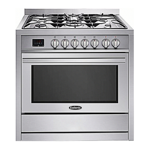
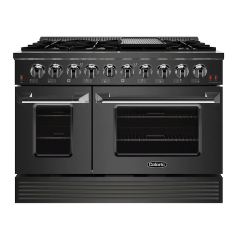
Caloric CSG7103 User manual

Please Read Manual Before
Operating Range
• Safety
• Installation
• Use
Installer
Leavethismanualandotherliteraturewithconsumerfor
futureuse.
Customer
Keeptheseinstructionsforfuturereference.Ifappliance
changesownership,be sure this manual accompanies
range.
Gas Range
Owner's Manual
Model CSG7103
Sealed Surface Burners
Electronic Oven Control
with Self-Cleaning Oven

2
Contents Model Identification
Completeenclosed registration card andpromptly return.
If registration card is missing, call Consumer Affairs
Departmentat1-800-843-0304 inside U.S.A.
319-622-5511outside U.S.A. When contacting Caloric
Sales Co. L.P., provide productinformationlocated on
rating plate. Rating plate is located on the oven frame.
Recordthefollowing:
ModelNumber: ______________________________
ManufacturingNumber: ________________________
Serialor S/N Number: _________________________
Dateofpurchase: ____________________________
Dealer’sname and address: ____________________
__________________________________________
__________________________________________
ImportantSafetyInformation........................................ 3
Installation................................................................... 6
ConvertingforUse with LP/Propane ............................ 9
ConvertingforUsewithNatural Gas .......................... 11
OperatingSurfaceBurners ........................................ 16
UtensilRecommendations ........................................ 17
DisplayandFeatures ................................................ 18
ServiceCodesand Tones .......................................... 18
Setting Clock and Timer ............................................ 19
AdjustingFactorySet Baking Temperature................ 19
Baking & Broiling ...................................................... 20
Self-Clean ................................................................. 22
UserMaintenance ..................................................... 23
CookingGuidelines ................................................... 24
Cleaning.................................................................... 26
BeforeCallingfor Service........................................... 27
Warranty ................................................................... 28
Recognize Safety Symbols, Words,
Labels DANGER
!
DANGER—ImmediatehazardswhichWILL result in
severepersonalinjuryordeath.
WARNING
!
WARNING—Hazards or unsafe practices whichCOULD
resultinseverepersonalinjury or death.
CAUTION
!
CAUTION—Hazardsor unsafe practiceswhich COULD
resultin minor personal injury or productor
propertydamage.
What You Need to Know about Safety
Instructions
Warning and Important Safety Instructions appearing in this
manual are not meant to cover all possible conditions and
situations that may occur. Common sense, caution, and care
must be exercised when installing, maintaining, or operating
range.
Always contact your dealer, distributor, service agent, or
manufacturer about problems or conditions you do not
understand.
Parts and Accessories
Purchasereplacement parts and additionalaccessories
(e.g.,oven racks, cooktop modules)over the phone. To
order accessories for your Caloric Sales Co. L.P.
product,call 1-800-843-0304 inside U.S.A.or
319-622-5511outsideU.S.A.
Service
Keep a copy of sales receipt for future reference or in
case warranty service is required. Any questions or to
locateanauthorizedservicer, call 1-800-NAT-LSVC
(1-800-628-5782)insideU.S.A.319-622-5511outside
U.S.A. Warranty service must be performed by an
authorizedservicer. Caloric Salesalso recommends
contactingan authorized servicer if serviceis required
afterwarrantyexpires.
Asure™ Extended Service Plan
CaloricSales Co. L.P.offerslong-term service protection
for this new range. Asure™ Extended Service Plan is
specially designed to supplement Caloric Sales’ strong
warranty. This plan coversparts,labor,andtravel
charges.Call1-800-528-2682forinformation.

3
IMPORTANTSAFETYINFORMATION
CAUTION
!
Do not obstruct the flow of combustion or
ventilationair.
WARNING
!
To avoiddeath,personalinjury or property damage,
information in this manual must be followed exactly.
Do not store or use gasoline or other flammable
vapors and liquids in the vicinity of this or any other
appliance.
WHAT TO DO IF YOU SMELL GAS
• Do not try to light any appliance.
• Do not touch any electrical switch; do not use
anyphonein your building.
• Immediatelycall your gas supplier from a
neighbor’sphone.Followthegas supplier’s in-
structions.
• If you cannot reach your gas supplier, call the
fire department.
Installationandservicemustbe performed by a
qualifiedinstaller,serviceagencyorthegassupplier.
WARNING
!
To reduce risk of the appliance tipping, it must
be secured by a properly installed anti-tip
bracket(s). To make sure bracket has been
installed properly, remove the storage drawer
and look under the range with a flashlight.
Bracket(s) must be engaged in the rear corner of
the range.
• ALL RANGES CAN TIP
• INJURY TO PERSONS
COULD RESULT
• INSTALL ANTI-TIP
BRACKET(S) PACKED
WITH RANGE
• SEE INSTALLATION
INSTRUCTIONS
WARNING
!
To avoid personal injury, do not sit, stand or lean on
ovendooror ovendrawer.
WARNING
!
To avoid risk of electrical shock, personal injury, or
death,make sure your range has been properly
groundedand always disconnect it frommain power
supplybeforeany servicing.
California Safe Drinking Water and
Toxic Enforcement Act(Proposition 65)
TheGovernorofCaliforniaisrequiredtopublisha list of
substances known to the state of California to cause
cancerorreproductiveharmandrequiresbusinessesto
warn customers of potential exposures to such
substances.
Someappliances contain or produce a chemical or
chemicals which can cause death or serious illness and
which are known to the State of California to cause
cancer, birth defects, or other reproductive harm. To
reduce the risk from substances in the fuel or from fuel
combustion, or that may be released during the self-
cleaning cycle, make sure this appliance is installed,
operated,andmaintainedaccordingtothemanufacturer’s
instructions.
SAVETHESEINSTRUCTIONS

4
IMPORTANTSAFETYINFORMATION
SURFACE COOKING UNITS
1. UseProperPanSize—Thisappliance is equipped
withoneormoresurface burners of different sizes.
Selectutensilshaving flat bottoms large enough to
coverthesurfaceburnerflame.The use of undersized
utensils will expose a portion of the burner flame to
direct contact and may result in ignition of clothing.
Properrelationshipof utensil to burner will also
improveefficiency.
2. NeverLeaveSurfaceBurnersUnattended—Boilover
causes smoking and greasy spillovers that may
ignite.
3. ProtectiveLiners—Donot use aluminum foil to line
surface unit drip bowls or oven bottom, except as
suggestedinmanual.Improperinstallation of these
liners may result in a risk of electric shock, or fire.
4. GlazedCookingUtensils—Only certain types of
glass, ceramic, earthware, or other glazed utensils
aresuitableforrangetopservicewithout breaking due
tosuddenchangeintemperature.
5. UtensilHandlesShouldbeTurned Inward and Not
ExtendOverAdjacentSurfaceBurners—Toreduce
the risk of burns, ignition of flammable materials, and
spillage due to unintentional contact with the utensil,
the handle of a utensil should be positioned so that it
isturnedinward, and does not extend over adjacent
surfaceunits.
ALL APPLIANCES
1. ProperInstallation—Be sure your appliance is
properlyinstalledandgroundedbyaqualified
technician.
2. NeverUseApplianceforWarmingorHeatingthe
Room.
3. Do NotLeaveChildrenAlone—Childrenshouldnot be
aloneorunattendedintheareawheretheappliance
is in use. They should never be allowed to sit or stand
on any part of the appliance.
4. WearProperApparel—Loosefittingor hanging
garmentsshouldneverbewornwhile using appliance.
5. UserServicing—Donotrepairorreplaceanypartof
theapplianceunless specifically recommended in the
manual.Allotherservicingshould be referred to a
qualifiedtechnician.
6. StorageinoronAppliance—Flammablematerials
shouldnot be stored in oven ornear surface units.
7. DoNotUse Water on Grease Fires—Smother fireor
flame,or use dry chemical or foam-typeextinguisher.
8. UseOnlyDry Potholders—Moist or damp potholders
on hot surfaces may result in burns from steam. Do
not let potholder touch elements. Do not use a towel
or other bulky cloth.
SAVE THESE INSTRUCTIONS
SELF-CLEANING OVEN
1. DoNotClean Door Gasket—The door gasket is
essential for a good seal. Care should be taken not to
rub,damage,or move the gasket.
2. DoNotUse Oven Cleaners—No commercialoven
cleanerorovenlinerprotectivecoatingofanykind
should be used in or around any part of the liner.
3. Clean Only Parts Listed in Manual.
4. BeforeSelf-Cleaningthe Oven—Removebroilerpan,
ovenracks, and other utensils.
5. Removeallitemsfromrangetopand backguard.
OVEN
1. UseCareWhen Opening Door—Let hot air or steam
escapebeforeremoving or replacingfood.
2. DoNotHeat Unopened Food Containers—Build-upof
pressure may cause container to burst and result in
injury.
3. KeepOvenVents Ducts Unobstructed.
4. PlacementofOvenRacks—Alwaysplace oven racks
in desired location while oven is cool. If rack is
removedwhileovenishot,donotletpotholder
contacthotheating element in oven.
VENTILATION HOOD
1. CleanVentilation Hood Frequently—Grease should
not be allowed to accumulate on hood or filter.
2. Whenflamingfoods under hood, turn fanon.

5
In Case of Fire
Fires can occur as a result of over cooking or excessive
grease. Though a fire is unlikely, if one occurs, proceed
as follows:
Surface Fire
1. Smotherthefire with a nonflammable lid or baking
soda, or use a Class ABC or BC extinguisher. Not
water. Not salt. Not flour.
2. As soon as it is safe to do so, turn the surface
burnercontrols to
OFF
.
• Asan added precaution, turn off gas supplyand
power at main circuit breaker or fuse box.
Oven Fires
1. If you see smoke from oven, do not open oven door.
2. Turnovenoff.
3. As an added precaution, turn off gas supply and
power at main circuit breaker or fuse box.
4. Turn on vent to remove smoke.
5. Allow food or grease to burn itself out in oven.
6. If smoke and fire persist, call fire department.
7. If there is any damage to components, call repair
service before using range.
Precautions
• Do not cook food directly on rangetop surface, always
usecookware.
• Do not mix household cleaning products. Chemical
mixturesmay interact with objectionable or even
hazardousresults.
• Oven door contains a glass window. While this glass is
built to be sturdy and resistant, it is glass and should
be treated with care.
• Donot lift or move range bygrasping oven door.This
can result in window glass breaking or shattering.
• Do not put plastic items on warm cooking areas. They
may stick and melt.
• Do not slide rough metal objects across rangetop
surface. Scratching or metal marking can result.
• Do not use damp sponge or dishcloth to clean rangetop
when range is hot. Steam from sponge or dishcloth can
burn.
• Do not leave fat heating unless you remain nearby. Fat
can ignite if overheated by spilling onto hot surfaces.
• Do not allow pots to boil dry as this can cause damage
to cooking surface and pan.
• Do not use rangetop surface as a cutting board.
Delayed Ignition
Surface Burners
Burnershould ignite within 4 seconds. Ifburner does not
ignite within 4 seconds turn control knob to
OFF
position
andfollowdirectionsin“Placing Grates and Burner Caps”
and“BeforeCallingforService”section. Try burner again.
If burner still does not ignite in 4 seconds, contact an
authorizedservicer.
Bake Burner Flame
Allownomorethan40–60secondsbeforeburnerignites
and heat is felt. To check for heat, open oven door to first
stopandplace hand over oven door.Ifheat is not felt,
pressOVENCANCELonovencontrol.Ifburner
repeatedlyfails to ignite, contact an authorizedservicer.
Broiler Flame
Allownomorethan40–60secondsbeforeburnerignites
and flame is seen. If burner does not ignite press OVEN
CANCELonovencontrol.Ifburnerrepeatedlyfailsto
ignitewithin40–60 seconds contact an authorized
servicer.
Radiantscreenstyle broiler flame should appear hazyor
fuzzy. Haze should be no more than 3/8inch thick. The
radiantscreenshouldbeginto glow red or orange within
1–2minutes.
IMPORTANTSAFETYINFORMATION
SAVE THESE INSTRUCTIONS

6
Minimum Clearances to Combustible
Surfaces
• Minimum clearance to rear wall is 0 inches.
• Minimum clearance to a vertical right or left side wall
extendingabovecooking surface is 3 inches.
• Minimumclearanceto countertop/cabinet on each side
is 0 inches.
• Minimumof30 inches between top of cookingsurface
andbottomof an unprotected wood or metalcabinet.
• 24inchesbetweencookingsurfaceandprotectedwood
ormetalcabinet above range. Cabinet bottom must be
protected by at least ¼ inch thick millboard with not
less than No. 28 MSG sheet steel, .015 inch thick
stainless steel, .024 inch thick aluminum, or .020 inch
thick copper.
A
B
C
D
EF
G
H
J
A—30inches minimum
B— 0 inches
C—30 inches unprotected/24 inches protected minimum
D—13 inches
E—0 inches
F—25 inches maximum
G—36 inches maximum
H—3 inches minimum (Both sides of range)
J—18 inches minimum
Minimum Clearances to Combustible Surfaces
Packing Material
Remove protective packing material from range. Tape
residue can be cleaned with a soft cloth and alcohol.
Range Location
Choose a location based on following factors.
• Draftscausedby home heating and air conditioning and
opendoorsorwindowscandisruptventilationair
pattern.Rangeshouldnotbe installed near windows or
doors.
• Makesurethere is adequate space for proper
installation.
• Carefullyreadallinstructionsbeforebeginning
installation.
Cabinet Opening
WARNING
!
To avoid risk ofburns or fire by reachingover burners,
cabinetstorage space located above range shouldbe
avoided.
Range should extend approximately 2 inches from
cabinet front to oven door handle. Use dimensions in
figurebelowandshownin
SpecialCountertopConditions
sectiontopreparecabinetopening.
A
C
B
D
A—301/8to 30¼ inches
B—36 inches standard
C—35 inches standard
D—23 inches standard
Standard Cabinet and Countertop Height
Installation

7
Special Countertop Conditions
Countertops such as ceramic tile tops cause cabinet and
countertoptobehigherthan36inches. Followinstructions
belowwhencountertopishigherthan 36 inches.
1. Raiselevelinglegstomaximum level.
2. Measurefromfloor to side trim. Ifmeasurement is
less than height of countertop floor must be shimmed.
3. Shim floor using a piece of plywood same size as
rangeopening. Secureplywoodtofloor. Plywood
must be as secure as original flooring.
4. Install anti-tip bracket(s) and slide range into place.
Electrical Connection Requirements
WARNING
!
To avoid the risk of serious electrical shock or property
damage,do not cut or remove thethird (ground) prong
fromthe power plug. A 3-wire grounded conductor
system must be used. Relying on the flexible
connector, hard piping or any other part of the gas
supply line as a ground may cause fire, electrical
shockand/or erratic control operation.
Rangemust be electrically groundedin accordance with
local codes or in the absence of local codes, with the
NationalElectrical Code, ANSI/NFPA No. 70-Latest
Edition.
In Canada, electrical connections are to made in
accordancewith CSA C22.1 CanadianElectrical Code.
All electrical connections are to be made in accordance
withCSA standards Z240.6.1 electrical requirementsfor
mobilehomes.
Usea 120 volt, 60 hertz, 3-prongreceptacle protected by
a 15 amp circuit breaker or time delay fuse. A qualified
electricianshouldconfirm the outlet is properly grounded.
Ifa 2-prong outlet is encountered,range owner must
replace outlet before using range. Do not cut off cord, use
plugadapteror extension cord, or remove groundingplug.
Grounded Plug and Receptacle
Electrical Connection Clearance
Electrical connection must be located in the area shown.
Electricalconnectionmustnotinterferewithgasconnection.
A
B
C
D
A
A—2 inches (Both sides)
B—19½ inches
C—12 inches
D—6 inches
ElectricalConnectionClearance
Gas Connection Requirements
Before connecting this appliance to the gas supply piping
system,confirm installationmeetstherequirementsoflocal
codes, or in the absence of local codes, with the National
FuelGasCode,ANSIZ223.1-LatestEdition.
When installed in mobile housing, installation is to be in
accordancewithCSAstandardZ241.1gasequipped
mobilehousing.
Theinstallationofappliancesdesigned for manufactured
(mobile)homeinstallation must conform with
ManufacturedHomeConstructionandSafetyStandard,
Title 24 CFR, Part 3280, or when such standard is not
applicable,theStandardforManufactured Home
Installation,ANSI225.1/NFPA501A-Latest Edition, or with
localcodesorthestandard CAN/CSA-z240MH, “Mobile
Homes”,andwithlocalcodes where applicable.
The installation of appliances is to be in accordance with
CAN1-B149.1orB149.2installationcodeforgasburning
appliances and equipment and/or local codes. Part 1 and/
or local codes.
Installation (cont.)
• Referto National Fuel Gas Code orlocal codes for
supply pipe size requirements to assure sufficient gas
supply to unit.

8
Pressure Regulator Location
Remove rear cover to expose pressure regulator.
Regulator Cover
Oven Shutoff Valve
Gasvalve to oven is turned onat factory, but could
accidentlybeturnedoffduringinstallation.Verify valve is
turnedon.
H
RA A
G
H
RA A
G
On
Off
Check Oven ShutoffValve
Gas Supply Location
Gas supply must be located in the area shown. Gas
connection must not interfere with the electrical
connection.
A
BCD
A
B
A—26 inches
B—20 inches
C—2¼ inches
D—4 inches
Gas Supply Location
Gas Supply Pressure
CAUTION
!
To avoidproperty damage, maximum gassupply
pressure must not exceed 14" WCP.
• Applianceandindividual shutoff valve mustbe
disconnected from the gas supply piping system during
any pressure testing of that system at test pressures in
excess of ½ psig (3.5kPa) (14" WCP).
• Appliance must be isolated from gas supply piping
systembyclosingmanualshutoff valve during any
pressure testing of the gas supply piping system at
test pressures equal to or less than ½ psig (3.5kPa)
(14"WCP).
• Gassupplypressure for checking regulator setting
must be at least 1" WCP above manifold pressure
shownonratinglabel.
Installation (cont.)

9
Thisrangearrives from factoryadjusted for use with
natural gas. If using LP/Propane gas is desired, range
mustbeconverted.See“Type1”or“Type 2” regulator.
Converting Type 1 Pressure Regulator for Use with
LP/Propane
1. Removepressureregulatorcapwitha wrench.
2. Removeplasticinsertfrompressureregulatorcap.
• Plastic insert fits tightly in cap.
3. Reverseplasticinsert and carefully push plastic
insert firmly into hole in pressure regulator cap.
• Capmustshow“LPG10”or “LP10”.
A
B
C
A—Cap
B—Plastic Insert (LP setting)
C—Spring Location
Type 1 Pressure Regulator
4. Placepressureregulatorcaponpressureregulator
andtighten.
• Insertshouldnot disturb spring in body ofregulator.
Converting Type 2 Pressure Regulator for Use with
LP/Propane
1. Removepressureregulatorcapwitha wrench.
2. Reversepressureregulatorcap.
• Cap must show “LP”.
3. Placepressureregulatorcaponpressureregulator
andtighten.
Cap
LP
Type 2 Pressure Regulator
WARNING
!
To avoid electric shock that can cause personal injury
or death, disconnect main electrical supply to range
beforeservicing.
Converting for Use With LP/Propane Gas

10
Converting Surface Burners for Use with LP/Propane
1. Remove4burnercontrolknobs from range.
• Exposes 2 screws on burner control panel.
2. Remove2screwsfromburnercontrol panel.
• Paneldropsslightlyafterscrews are removed.
3. Graspbottomof burner control panel, gently liftand
pulloutpanel until clear of burner valve stems.
• Afterburnercontrolpanelclearsvalvestems,
continueto roll panel until free fromrange. Set
aside. See
Pivot Point
in figure.
• Gasvalveand orifice hood arevisibleafterburner
controlpanelisremoved.
AB
C
D
A—Burner Control Knob
B—Pivot Point
C—Burner Control Panel
D—Screw
Burner Control Panel
4. Whilefacingrange front, turn orificehoods
counterclockwise 1½ to 2 turns or until snug.
• Use½ inch open end or 90° offsetopen end
wrench.
• Donotovertightenorificehoods.Iforificehoods are
overtightened,gas supply can be cutoff or orifice
hoods can strip.
5. Openairshutter fully.
A
B
Open Fully
A—Orifice Hood
B—Air Shutter
Converting Surface Burners for Use with LP\Propane
andairshutter.
3. Turnorificehood clockwise until snug.
• Donotovertightenorificehoods.Orificehoodscan
strip.Supportorifice fitting with wrench to avoid
damage to gas supply tubing.
4. Replacecoverplateand storage drawer.
A
B
C
A—Air Shutter Screw
B—Orifice Hood
C—Air Shutter
Converting Oven Burner
6. Reassembleburnercontrolpanelafteradjustingair
shutter.
• See
Adjusting Surface Burner Flame
section.
Converting Oven Burner for Use with LP/Propane
1. Removestoragedrawer.
• See
RemovingStorageDrawer
section.
2. Locateandremove2screwsattachingZ-shaped
coverplate.
• Coverplatelocatedincenter, rear of storage drawer
cavity.
• Removingcoverplate exposes ovenburnerorifice
Converting for Use With LP/Propane(cont.)

11
Converting Broiler Burner for Use with LP/Propane
1. Locate orifice spud attached adjacent to pressure
regulatorandremovefor later use.
• Orificespudused for LP/Propane gas is silverand
is stamped “58”.
2. Openovendoor and locate broilerburneronoven
ceiling.
• Removeovendoor to make conversioneasier.See
RemovingOvenDoor
section.
3. Remove2screwssecuringfrontof burner to oven
ceilingandremove broiler.
• Becarefulnottodamageignitorwhileremoving
broiler.
4. Unscrewnaturalgasburnerspudstamped“52”
with 5/16 inch socket wrench and replace with
LP/Propaneburnerspudstamped“58”.
• Attachunusedburnerspudnearregulator for future
use.
5. Reinstallbroilerand,ifnecessary, oven door.
A
B
C
A—Screw
B—Broiler
C—Spud/Orifice
Converting Broiler Burner
Converting Type 1 Pressure Regulator for Use with
Natural Gas
1. Removepressureregulatorcapwitha wrench.
2. Removeplasticinsertfrompressureregulatorcap.
• Plastic insert fits tightly in cap.
3. Reverse plastic insert and carefully push plastic insert
firmlyinto hole in pressure regulator cap.
• Insertmust show “NAT” or be blank.
4. Placepressureregulatorcaponpressureregulator
andtighten.
• Insertshouldnot disturb spring in body ofregulator.
Converting Type 2 Pressure Regulator for Use with
Natural Gas
1. Removepressureregulatorcapwitha wrench.
2. Reversepressureregulatorcap.
• Insert shows “NAT” or is blank.
3. Placepressureregulatorcaponpressureregulator
andtighten.
Converting Surface Burners for Use with Natural Gas
1. Remove4burnercontrolknobs from range.
• Exposes 2 screws on burner control panel.
2. Remove2screwsfromburnercontrol panel.
• Paneldropsslightlyafterscrews are removed.
3. Graspbottomof burner control panel, gently liftand
pulloutpanel until clear of burner valve stems.
• Afterburnercontrolpanelclearsvalvestems,
continueto roll panel until free fromrange. Set
aside.
• Gasvalveand orifice hood arevisibleafterburner
controlpanelare removed.
4. Whilefacingrange front, turn orifice hoods clockwise
1½ to 2 turns.
• Use½ inch, 90° offsetopen end wrench.
5. Reassembleburnercontrolpanelafteradjustingair
flowtosurfaceburnerflame.
• See
Adjusting Surface Burner Flame
section.
Converting Oven Burner for Use with Natural Gas
1. Removestoragedrawer.
•
RemovingStorageDrawer
section.
2. Locateandremove2screwsattachingZ-shaped
coverplate.
• Coverplatelocatedincenter,rear of storage
drawercavity.
• Removingcoverplate exposes ovenburnerorifice
andairshutter.
3. Turnorificehood counterclockwise 2 full turns.
Supportorificefittingwithwrenchtoavoiddamage
to gas supply tubing.
4. Replacecoverplateand storage drawer.
Converting Broiler Burner for Use with Natural Gas
1. Locateorificespud attached adjacent to pressure
regulatorandremovefor later use.
• Orifice spud used for natural gas is brass colored
and is stamped “52”.
2. Openovendoor and locate broilerburneronoven
ceiling.
• Removeovendoor to makeconversioneasier.
See
RemovingOvenDoor
section.
3. Remove2screwssecuringfrontof burner to oven
ceilingandremove broiler.
• Becarefulnot to damage ignitor as youremove
broiler.
4. UnscrewLP/propaneburnerspud stamped “58”
with 5/16 inch socket wrench and replace with natural
gasburnerspudstamped“52”. Attach unused burner
spudnearregulatorforfutureuse.
5. Reinstallbroilerand,ifnecessary, oven door.
Converting for Use with Natural Gas

12
WARNING
!
To avoidpropertydamage or serious personal injury,
never use a lighted match to test for gas leaks.
1. Mix container with soapy water
2. Place soap suds on connection.
• Bubbles appear if leak is present.
3. Ifbubblesappear, shut offgassupplyvalve.
4. Tighten joint if leak is at factory fitting.
• If leak is not at factory fitting, unscrew, apply more
joint compound, and tighten to correct leak.
5. Retestconnectionfor leak after tightening.
• Retest any connections that were disturbed.
Test for Gas Leaks
Gas Connection
Connectgassupply to regulator using hard pipeorflexible
connector(Checklocalcodes).Pressure regulator
supplied with this appliance has a ½ inch NPT female
connection.Ifgasunionisused,removestoragedrawer,
slide range into place, and connect union.
• Referto National Fuel Gas Code orlocal codes for
supply pipe size requirements to assure sufficient gas
supply to unit.
• A manual shutoff, not supplied with range, must be
installed in an accessible location outside of range.
• Use joint compound that is resistant to action of
propanegason all male pipe threads.
• Usesuppliedpressureregulatoronly.
• Donotovertighten gas fitting when attaching to
pressureregulator. Overtightening may crackregulator.
• Supportpressureregulatorwithwrenchwheninstalling
gas fitting.
WARNING
!
To avoidproperty damage or personal injury, onlyuse
a new flexible connector that is AGA/CGA design
certified.
• Do not use an old connector.
• Do not reuse a connector after moving appliance.
A
B
C
D
A—Regulator
B—Adaptor
C—FlexibleConnector
D—Manual Shut OffValve
FlexibleConnection
ABC
DE
F
A—Union
B—Manual Shut OffValve
C—Reducing Elbow (3/4-inch to 1/2-inch)
D—3/4-inch Stub
E—1/2-inchNipple
F—Regulator
Hardpipe Connection
Testing for Gas Leaks
After final gas connection is made, turn on manual gas
valve and test all connections in gas supply piping and
range for gas leaks. Leak testing of the appliance shall be
conductedaccordingto the manufacturer’s instructions.
Gas Connection

13
Seal Openings
Openingsin wall behind the rangeor on floor underrange
must be sealed before sliding range into position.
Anti-tip Bracket Installation
To reducerisk of range tipping, secure rangewith a
properlyinstalledanti-tip bracket.
1. Measure 31/2inches from back wall on right and left
sideof cabinet cutout. Mark measurements on floor
and draw a straight line connecting marks.
2. Position anti-tip bracket.
• Ifrange is installed besidecabinet(s), place anti-tip
bracketwith back edge on line drawnon floor and
side of bracket against cabinet.
• If range is not installed beside cabinet(s), position
rangewhere it will be installed. Draw aline along
sideofrangeonfloorfromfronttoback. Remove
range.Placeanti-tip bracket with back edge over
line drawn 31/2inches from back wall and side of
bracketoverlinedrawnalongsideofrangeonfloor.
• Anti-tip bracket can be installed on either right or
left side.
or
31/2"
Anti-tipBracketInstallation
3. Mark 2 hole locations in anti-tip bracket.
4. Drill 2 holes.
• If drilling into wood, use a 3/32 inch drill bit.
• If drilling into concrete, use a 3/16 inch masonry drill
bit and insert plastic anchors.
5. Secure bracket to floor using screws supplied.
6. Sliderangeinto position.
7. Removerangestorage drawer andconfirmanti-tip
bracketisengagedwithrangelevelinglegafterrange
is in place.
Place Range
Pluginrange.Sliderange into place. Carefully level range
usinglegsprovided. Range must be level tocookand
bakeuniformly.
• Placea level on top oven rackor on top of rangewhen
leveling.
• Leveling legs must be extended out ¼ inch to engage
anti-tipbracket.
Removal and Reinstallation of Range
1. Unplugrangecord.
2. Turnoffgas valve and disconnect gas supply.
3. Removerangeand place aside.
4. Removeanti-tipbracketandreinstall anti-tip bracket
intonewlocationusinginstructions provided with
bracket.
5. To reinstall range, follow instructions in
Installation
section of this manual.
• Donotreuseaflexibleconnectoraftermoving
appliance.
Place Grates and Burner Caps
Placeburnercaponburner base and grate on rangetop.
A
B
C
A—Burner grate
B—Burner cap
C—Burner base
Place Grates and Burner Caps
Pegs in the burner base fit into recess in underside of
burnercap. To make sure cap is properly aligned and
leveled,moveburner cap around onburnerbase.Burner
capmust be correctly seated on burnerbase for proper
operationof burner.
Make sure proper cap size is on each burner base.
Burnerdoesnot burn properly if wrong sizeburnercap is
placedonburnerbase.
Turnonburnerstocheckforproperoperation.See
OperatingSurfaceBurners
sectionforburneroperating
instructions.
Anti-Tip and Burner Installation

14
Adjusting Air Shutter
1. Remove4burnercontrolknobs from range.
• Exposes 2 screws on burner control panel.
2. Remove2screwsfromburnercontrol panel.
• Paneldropsslightlyafterscrews are removed.
3. Graspbottomof burner control panel, gently liftand
pulloutpanel until clear of burner valve stems.
• Afterburnercontrolpanelclearsvalvestems,
continueto roll panel until free fromrange. Set
aside. See
Pivot Point
in figure.
• Gasvalveand orifice hood arevisibleafterburner
controlpanelisremoved.
AB
C
D
A—Burner Control Knob
B—Pivot Point
C—Burner Control Panel
D—Screw
Burner Control Panel
4. Slide air shutter open or closed depending on
appearanceofburnerflame.
• If flame is yellow and does not hold its shape, open
airshutter.
• If flame is blowing or noisy, close air shutter.
5. Reassembleburnercontrolpanel.
Open Close
AdjustingAir Shutter
Correct
Not centered Too small Too large
Burner Caps
Test and Adjust Surface Burner Flame
WARNING
!
To avoid electric shock that can cause personal injury
or death, disconnect main electrical supply to range
beforeservicing.
Turn on burner. See
Operating Surface Burners
section
forburneroperatinginstructions.Surfaceburner should
ignitewithin4 seconds. Properly adjusted surface burner
flames are clean and blue with a distinct inner cone
approximately ¼ inch to ½ inch long. Some yellow tipping
ontheflameisnormalwhenburningLP/Propane.
See Adjusting Air Shutter section,
• Ifburnerflame is blowing or noisy, reduce airflowto
burner.
• Ifburnerflame does not hold its shape, increase airflow
toburner.
A
Burner
A—¼ inch to ½ inch long
Surface Burner Flame
Burner Installation (cont.)

15
Test and Adjust Oven Burner Flame
Properlyadjustedovenburnerflamesarebluewitha
distinct deep blue inner cone approximately ½ inch long.
Whenusingnatural gas, flame should not haveanyyellow
flamewhenburning.Someyellowtipping when burning
LP/Propanegasis normal.
1/2"
ProperlyAdjusted Flame
Flameshouldnot be visible in the oven cavity when
burningandshould not extend into the oven cavity beyond
theremovableovenbottom.
Removing Oven Bottom
CAUTION
!
To avoidrisk of cuts, wear protective gloveswhen
removingovenbottom.Sharp edges around oven
bottom can cut.
1. Pullovenbottom forward and lift out.
2. Replaceovenbottom. Oven bottom hastabs in rear
that fit into oven floor slots.
BurnerArea
Adjust Oven Burner Flame
1. Removestoragedrawer.
• See
RemovingStorageDrawer
section.
2. Locateandremove2screwsattachingZ-shaped
coverplate.
• Coverplatelocatedincenter, rear of storage drawer
cavity.
• Removingcoverplate exposes ovenburnerorifice
andairshutter.
3. Loosen air shutter lock screw and open or close air
shutter.
• Ifburnerflame is blowing or noisy, reduce airflowto
burner.
• If burner flame is yellow and does not hold its
shape,increaseairflowtoburner.
• Some yellow tipping on the flame is normal when
burningLP/Propane.
• Tightenair shutter lock screw after adjusting.
4. Replacecoverplateand storage drawer.
A
B
C
A—Air Shutter Screw
B—Orifice Hood
C—Air Shutter
Adjusting Oven Burner Flame
Broiler Flame
Radiant Screen Style
Broilerflame should appear hazy or fuzzy.Haze should
be no more than 3/8inch thick. The radiant screen should
begintoglow red or orange within 1–2minutes.
Because broiler has a fixed orifice it can not be adjusted.
Broilerdoesnot have an air shutter.
Burner Installation (cont.)

16
Adjusting Burner Flame Size
• Whileturningthe burner control knob, watch theburner
flame.
• Flame size should match the size of the pan. Do not
allow the flame to extend up the sides of the pan.
Flames that extend up the sides of the pan can ignite
clothing, make handle hot, or burn.
Adjusting Burner Flame Size
Operating Surface Burner during a Power
Failure
Although the system that lights the burners is electric,
surfaceburnerscanbeignitedduringapowerfailure.
Never attempt to light bake or broil burners during
power failure.
1. Holdmatchat base of desired burner.
2. Push in burner control knob and turn to
LITE
position.
3. Aftergasignites,removematch from burner and turn
burnercontrol knob to desired setting.
Operating Surface Burners
WARNING
!
To avoidrisk of serious personalinjury, property
damage,orfire, do not leave burners unattended while
inoperation. Grease and spilloversmay ignite causing
afire.
1. Pushburner knob in andturn control knob
counterclockwise to
LITE
position.
• Burnershouldignite within 4 seconds. If burner
does not ignite within 4 seconds turn control knob
to
OFF
position and follow directions in “Placing
GratesandBurnerCaps”and“Before Calling for
Service”section.Tryburneragain.Ifburnerstill
does not ignite in 4 seconds, contact an authorized
servicer.
Burner Knob
2. After gas ignites, turn control to desired setting.
• Each control knob can be set to any required
cookingtemperature.Burnersettingsdonothave
distinct clicks.
• Use
HI
tobring food to boiling temperatures. When
foodisboiling temperature setting should be
reduced.
• Afterlightingburnerdonotoperateburnerforlong
periodsoftime without cookware on the grate.The
finish on the grate can chip without cookware to
absorbheat.
3. Turncontrolknob to
OFF
positionwhen finished
Canning
Canningrequiressustained, high heat. While canning can
be done on the gas range, these precautions must be
taken:
• Canningutensilmustnotoverhangthemetalburner
grate by more than one inch on either side.
• Burner flames must be adjusted to canning utensil size.
• Canning must be done on front elements only. By
canningonrearelement,damage to range backguard is
possible.
• Removeheat-susceptibleitemsfromareaof canning
utensilandrangetop.
O
F
F
H
I
L
I
T
E
G
A
S
O
N

17
Flat Bottom Pan Test
To avoid pan wobbling, use a pan with a flat bottom. To
determine if pan has a flat bottom:
1. Rotate a ruler along bottom of pan. If pan is not flat,
gapsbetween bottom of panand edge of ruleroccur.
2. A small groove or mark on a pan does not effect
cooking times. However, if a pan has a gap, formed
rings, or an uneven bottom, it does not cook
efficiently and in some cases may not boil liquid.
Flat Pan Test
Cooking Utensils
• Use proper pan size. Do not use a pan that has a
smaller bottom than surface burner. Do not use utensils
thatoverhanggrate by more than 1 inch.
More than 1 inch
overhang
Does not cover burner
Use Proper Pan Size
• Use care when using glazed cooking utensils. Some
glass,earthenware,or other glazed utensils break due
tosuddentemperaturechanges.
• Select utensils without broken or loose handles.
• Handlesshould not be heavy enough totilt pan.
• Do not use stove top grills on your range. Stove top grills
causeincompletecombustion and can create levels of
carbonmonoxideabove allowable standards.
• Do not use a wok with a ring stand. Use flat bottom
wok.
Woks
Utensil Recommendations
Utensil Material Characteristic
Type Temperature
Response Uses
Aluminum Heats and
cools quickly Frying, braising,
roasting
Cast Iron Heats and
cools slowly Low heat
cooking, frying
Copper Clad /
Tin Lined Heats and
cools quickly Gourmet
cooking, wine
sauces, egg
dishes
Enamelware Depends on
base metal Low heat
cooking
Ceramic (Glass) Heats and
cools slowly Low heat
cooking
Stainless Steel Heats and
cools at
moderate rate
Soups, sauces,
vegetables,
general cooking

18
TIMER
CLOCK
++
MINS
HRS MINS
OVEN LIGHT
SURFACE
HRS
Display and Features
Item Description
TIMER Pad Selects timer feature. Timer can be set up to 11 hours, 59 minutes. Timer does not control
oven operation.
TIMER
pad has light that flashes when timer is being set and glows when timer is counting
down. Timer light allows user to identify timer mode quickly and easily.
CLOCK Pad Pad is pressed to set clock and turn clock display on and off.
HRS Pad Pads increase or decrease time by hours.
MIN Pad Pads increase or decrease time by minutes.
Temperature knob Controls oven temperature, self-clean, and broil. Push-to-turn knob prevents accidentally
turning oven on.
OVEN light Glows when oven is on. Light flashes after self-clean cycle turns off as a reminder to turn
temperature knob to
OFF
.
LOCKED light Glows when oven door is locked and oven is set for self-cleaning. After self-clean cycle,
light flashes. Unlatch oven door and turn temperature knob to
OFF
.
PREHEATED light Glows when oven reaches selected temperature.
Time display Shows the time-of-day and timer minutes. Will not display AM, PM, or military time.
Other Features
12-hour automatic
cancel This safety feature prevents oven from continuing to heat if it has been left on for over 12
hours. This feature can be turned on or off while the temperature knob is in OFF position.
To operate oven for more than 12 hours press and hold the MINS+ and – pads for
approximately 4 seconds. Display will change from time-of-day to show ‘OFF’ and then
return to time display.
To set oven to shut off after 12 hours press and hold the MINS + and – pads for
approximately 4 seconds. Display will change from time-of-day to show ‘ON’ and then
return to time display.
Service codes
and tones Range control is equipped with a self-diagnostic system. This alerts you if there is an error
or problem in the control. If electronic range conrol sounds a series of short, rapid beeps
for over 16 seconds and display shows an F-code, disconnect electrical supply to range
and contact an authorized servicer.
F2—High oven temperature
F3—Temperature sensor
F4—Temperature sensor
FFF—Control failure

19
Adjusting Oven Temperature
Your new range is calibrated at the factory for
temperature.However, due toindividualvariancesand
preferences, it may be necessary to adjust individual
ovensoncethey have been installed.
When first using oven, follow recipe times and
temperatures.Beforeadjustingovenbakingtemperature,
test a recipe by using a temperature set higher or lower
thantherecommended temperature. The baking results
should help you to decide how much adjustment is
needed.
NOTE:Removealuminumfoilfromoven—itwillalteroven
performance. Check for blocked heat vents. If it still
appearsthe oven is not performing as expected,a
calibrationmay be done.
An accurate digital thermometer is necessary to
calibrateoven.Storepurchasedoventhermometersdo
notmeasureoven temperature accurately.
To change oven temperature throughovencontrol:
1. Turnoventemperature knob to OFF.
2. Press and hold HRS+ and HRS- pads for
approximately 5 seconds. A double digit number will
display.
3. Immediately, press either HRS+ or HRS- pad.
Setting the Clock and Timer
TIMER
CLOCK
++
MINS
HRS MINS
HRS
Setting Electronic Clock
When power is connected or restored, display flashes
until pad is pressed or temperature knob is turned.
Reset clock.
1. Verify display is flashing.
• Ifdisplaydoes not flash, press
CLOCK
padrepeat-
edly until display flashes.
2. Press
HRS
+ or - pad to set hours and
MINS
+ or -
pad to set minutes.
3. Press
CLOCK
padtosave time-of-day.
• Clocksavestime-of-dayapproximately60 seconds
after time is entered if
CLOCK
pad is not pressed.
Turning Off/On Clock Display
Press
CLOCK
pad until display is blank. Clock retains
time while not displayed. To turn on display, press
CLOCK
pad until time-of-day displays and is not flashing.
Setting Electronic Timer
The minute timer is a timer only. Electronic timer does
not control bake, broil, or self-clean function. Timer can
be set up to 11 hours and 59 minutes.
1. Press
TIMER
pad.
2. Press
HRS
+ or - pad to set hours and
MINS
+ or -
pad to set minutes.
• Timerbeginscountingdownautomaticallyafter
time is entered.
• To view clock while timer counts down, press
CLOCK
pad.Toviewtimeragain,press
TIMER
pad.
3. Press
TIMER
pad again to cancel.
Resetting and Canceling Timer
To reset or cancel timer, display must show remaining
time. If display does not show remaining time, press
TIMER
pad.
To reset the time when remaining time is displayed,
press the
HRS
+ or - pad to set hours and
MINS
+ or -
pad to set minutes until new time displays.
To cancel remaining time or signal after time elapses,
press
TIMER
pad. Signal sounds until canceled.
• HRS+increasesoventemperatureby5°F.
• HRS-decreasesoventemperatureby5°F.
• Oventemperaturecanbechangedupto35°F.
Whentemperature is adjusted cooler “-” showsin
displayfollowedbyoffsettemperature.
• Foreachcalibration,oventemperatureshouldonly
beadjusted by 5 degrees. This willprevent drastic
changes in baking results.
• Aftera few seconds control saves newsetting and
returnstopreviousdisplay.
• Controlwillretainoffsetthroughapowerfailure.
• Ifoven is still not generating desiredbaking results,
anotherovencalibration may be performed.

20
• Stagger pans placed on different racks so one is not
directlyoverthe other.
PanPlacement
CAUTION
!
To reduceriskof food poisoning due to bacterial
growthandproductionoftoxins,neverholdmeat,
milk, fish or eggs for more than 2 hours before
cooking.
Remove Items Stored in Oven
Remove any pans and other cooking utensils stored in
oven.
Remove Items Stored in Oven
WARNING
!
To avoiddamagingovenliner or creating fire, do not
lineoven bottom or ovenracks with foil oraluminum
liners.
Oven Rack Placement
Positionovenrack before turning oven on.
1. Pull rack forward to stop position.
2. Raise front edge of rack and pull until rack is out of
oven.
3. Place rack in new rack position.
• Curvededgeof rack must be toward rear of oven.
Aluminum Foil
When placed on the oven bottom or racks, aluminum foil
not only creates a hazard, but also affects cooking
performance.Tominimize spills in the oven, place a
shallowpan or cookie sheet underneath fooditems that
may drip or spill. Pan should not touch the oven walls,
backordoor.
Baking and Broiling
Broiling Tips
• Removeexcess fat from meat beforebroiling. Cut
edgesof meat to preventcurling.
• Place food on a cold ungreased broiling pan. If pan is
hot, food sticks.
• All food except fish should be turned at least one time.
Begin broiling with skin side down.
• Season meat after it has browned.
• Broilingdoesnotrequirepreheating.
• Begin cooking using suggested rack levels in
Broiling
Guide
section to test broiler results. If food is not brown
enough, cook on a higher rack position. If food is too
brown, cook on a lower rack position.
Table of contents
Languages:
Other Caloric Range manuals

Caloric
Caloric CSG3601 User manual

Caloric
Caloric CSG7601 User manual

Caloric
Caloric rks396 Instruction Manual

Caloric
Caloric EST399 User manual

Caloric
Caloric RLN330UW User manual

Caloric
Caloric CPR SERIES User manual

Caloric
Caloric ETR666 Operating instructions

Caloric
Caloric CSR 6203 User manual

Caloric
Caloric RLS112 User manual

Caloric
Caloric CDR365-SS Manual
Popular Range manuals by other brands

Eltac
Eltac EK 18 instruction manual

Electrolux
Electrolux C970-4407 Factory parts catalog

Inoksan
Inoksan 7 KG 10/S instruction manual

KitchenAid
KitchenAid KFED500ESS User instructions

Frigidaire
Frigidaire FGGF3031KQ - 30' Gas Range Gallery Mono... Product specifications

DeDietrich
DeDietrich EMIC800X manual