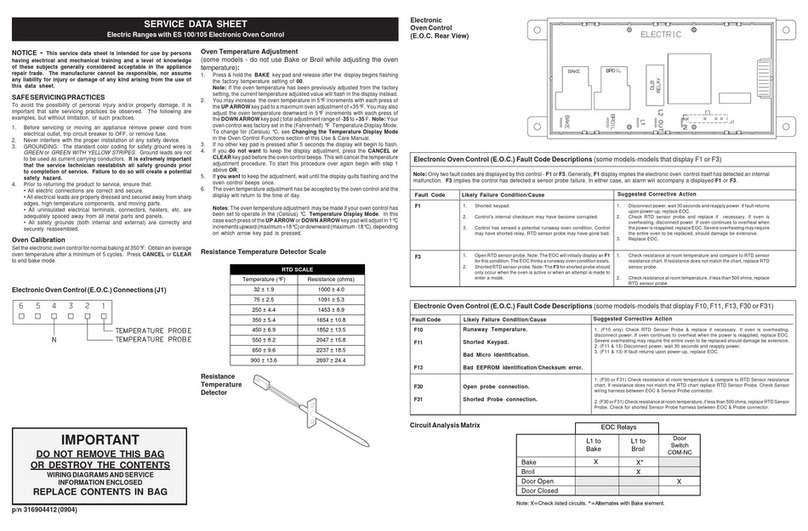
Caloric CSR 6203 User manual

Please Read Manual Before
Operating Range
• Safety
• Installation
• Use
Important
Save for local electrical inspector’s use.
Installer
Leavethismanualandotherliteraturewithconsumerfor
futureuse.
Customer
Keeptheseinstructionsforfuturereference.Ifappliance
changesownership,be sure this manual accompanies
range.
Electric Range
Owner's Manual
Model CSR 6203
Coiltop Range
with Self-Cleaning Oven

2
Contents
Model Identification
Completeenclosedregistrationcardandpromptlyreturn.
If registration card is missing, call Consumer Affairs
Departmentat1-800-843-0304insideU.S.A.
319-622-5511outsideU.S.A.WhencontactingCaloric
SalesCo.L.P.,provideproductinformationlocated on
ratingplate. Rating plate is located onthe oven frame.
Recordthefollowing:
ModelNumber: ______________________________
ManufacturingNumber: ________________________
SerialorS/N Number: _________________________
Dateofpurchase:_____________________________
Dealer’snameandaddress: ____________________
__________________________________________
__________________________________________
ImportantSafetyInformation........................................ 3
Installation................................................................... 6
UserMaintenance ..................................................... 11
OperatingSurfaceElements ..................................... 12
UtensilRecommendations ........................................ 13
DisplayandFeatures ................................................ 14
ServiceTones............................................................ 14
Setting Clock and Timer ............................................ 15
AdjustingFactorySet Baking Temperature................ 15
BakingandBroiling ................................................... 16
Self-Clean ................................................................. 18
CookingGuide .......................................................... 19
Cleaning.................................................................... 21
BeforeCallingfor Service........................................... 22
Warranty ................................................................... 24
What You Need to Know about Safety
Instructions
Warning and Important Safety Instructions appearing in this
manual are not meant to cover all possible conditions and
situations that may occur. Common sense, caution, and care
must be exercised when installing, maintaining, or operating
range.
Always contact your dealer, distributor, service agent, or
manufacturer about problems or conditions you do not
understand.
Parts and Accessories
Purchasereplacement parts and additionalaccessories
(e.g., cooktop accessories, grates, cleaning products)
overthe phone. To order accessories foryour Caloric
SalesCo. L.P. product, call1-800-843-0304 inside
U.S.A.or 319-622-5511 outside U.S.A.
Service
Keepa copy of sales receipt forfuture reference or in
case warranty service is required. Any questions or to
locateanauthorizedservicer,call1-800-NAT-LSVC
(1-800-628-5782)insideU.S.A. 319-622-5511outside
U.S.A.Warranty service must beperformed by an
authorizedservicer.Caloricalsorecommendscontacting
anauthorizedservicerifserviceis required after warranty
expires.
Asure™ Extended Service Plan
CaloricSalesCo. L.P.offerslong-term serviceprotection
forthis new range. Asure™ ExtendedService Plan is
specially designed to supplement Caloric Sales’ strong
warranty.Thisplancoversparts,labor, and travel
charges.Call1-800-528-2682 forinformation.
Recognize Safety Symbols, Words,
Labels DANGER
!
DANGER—ImmediatehazardswhichWILL result in
severepersonalinjuryordeath.
WARNING
!
WARNING—Hazardsor unsafe practices which COULD
resultinseverepersonalinjury or death.
CAUTION
!
CAUTION—Hazardsor unsafe practiceswhich COULD
resultin minor personal injury or productor
propertydamage.

3
IMPORTANTSAFETYINFORMATION
• ALL RANGES CAN TIP
• INJURY TO PERSONS
COULDRESULT
• INSTALLANTI-TIP
BRACKET(S) PACKED
WITHRANGE
• SEEINSTALLATION
INSTRUCTIONS
WARNING
!
To avoid risk of the appliance tipping, it must be
secured by a properly installed anti-tip
bracket(s). To make sure bracket has been
installed properly, remove the storage drawer or
panel and look under the range with a flashlight.
Bracket(s) must be engaged in the rear corner of
the range.
WARNING
!
To avoid personal injury, do not sit, stand or lean on
ovendooror ovendrawer.
WARNING
!
To avoid risk of electrical shock, personal injury, or
death,make sure your range has been properly
groundedand always disconnect it frommain power
supplybeforeservicing.
CAUTION
!
DONOTTOUCHSURFACE UNITSORAREAS
NEARUNITS—Surface units may behot though they
are dark in color. Areas near surface units may
becomehot enough to causeburns. During and after
use, do not touch, or let clothing touch or other
flammable materials contact surface units or areas
near surface units until they have had enough time to
cool. These areas include the rangetop and
backguard.
CAUTION
!
DONOTTOUCHHEATINGELEMENTSOR
INTERIORSURFACES OF OVEN—Ovenheating
elements may be hot though they are dark in color.
Interiorsurfacesof an oven may become hotenough
to cause burns. During and after use, do not touch, or
let clothing or other flammable materials touch heating
elementsor interior surfaces of oven untilthey have
had enough time to cool. Other range surfaces that
may become hot enough to cause burns are the oven
doorandoven vent.
SAVE THESE INSTRUCTIONS
California Safe Drinking Water and
ToxicEnforcement Act (Proposition65)
TheGovernorofCaliforniaisrequiredtopublisha list of
substances known to the state of California to cause
cancerorreproductiveharmandrequiresbusinessesto
warn customers of potential exposures to such
substances.
Someappliances contain or produce a chemical or
chemicals which can cause death or serious illness and
which are known to the State of California to cause
cancer, birthdefects,orotherreproductiveharm.To
reduce the risk from substances that may be released
during the self-cleaning cycle, make sure this appliance
isinstalled, operated, and maintainedaccording to the
manufacturer’sinstructions.

4
SURFACE COOKING UNITS
1. UseProperPanSize—Thisappliance is equipped
with one or more surface units of different size. Select
utensilshavingflatbottomslarge enough to cover the
surfaceunitheatingelement.Theuseofundersized
utensils will expose a portion of the heating area to
direct contact and may result in ignition of clothing.
Useofoversized utensils concentrates heat on
cookingsurface and can cause damage torange.
Properrelationshipof utensil to surface element
improvesefficiency.
2. NeverLeaveSurface UnitsUnattended—Boilover
causes smoking and greasy spillovers that may
ignite.
3. Make Sure Reflector Pans or Drip Bowls Are in
Place—Absenceofthese pans or bowls during
cooking may subject wiring or components
underneathtodamage.
4. ProtectiveLiners—Donot use aluminum foil to line
surfaceunitdripbowlsorovenbottom.Improper
installation of these liners may result in a risk of
electrical shock, or fire.
5. GlazedCookingUtensils—Only certain types of
glass, ceramic, earthware, or other glazed utensils
aresuitableforrangetopservicewithout breaking due
tosuddenchangeintemperature.
6. UtensilHandlesShouldBeTurnedInward and Not
ExtendOverAdjacentSurfaceUnits—To reduce the
riskof burns, ignition of flammable materials,and
spillage due to unintentional contact with the utensil,
the handle of a utensil should be positioned so that it
isturnedinward, and does not extend over adjacent
surfaceunits.
7. DoNotSoakRemovableHeating Elements—Heating
elementsshouldneverbeimmersedinwater.
IMPORTANT SAFETY INFORMATION
SAVE THESE INSTRUCTIONS
ALL APPLIANCES
1. ProperInstallation—Besure your appliance is
properlyinstalledand grounded by a qualified
technician.
2. NeverUseYour Appliance for WarmingorHeating
the Room.
3. Do Not Leave Children Alone—Children should not
bealone or unattended inthe area where the
appliance is in use. They should never be allowed to
sit or stand on any part of the appliance.
4. WearProperApparel—Loose-fittingorhanging
garmentsshould never be worn while usingthe
appliance.
5. UserServicing—Donot repair or replace any partof
theappliance unless specifically recommended in
the manual. All other servicing should be referred to a
qualifiedtechnician.
6. StorageInor On Appliance—Flammable materials
should not be stored in an oven or near surface units.
7. Do Not Use Water on Grease Fires—Smother fire or
flame, or use dry chemical or foam-type extinguisher.
8. UseOnlyDry Potholders—Moist or damp potholders
on hot surfaces may result in burns from steam. Do
not let potholder touch elements. Do not use a towel
or other bulky cloth.

5
OVENS
1. UseCareWhen Opening Door—Let hot air or steam
escapebeforeremoving or replacingfood.
2. DoNotHeat Unopened Food Containers—Build-upof
pressure may cause container to burst and result in
injury.
3. KeepOvenVentDuctsUnobstructed.
4. PlacementofOvenRacks—Alwaysplace oven racks
in desired location while oven is cool. If rack is
removedwhileovenishot,donotletpotholder
contacthotheating element in oven.
SELF-CLEANING OVENS
1. DoNotClean Door Gasket—The door gasket is
essential for a good seal. Care should be taken not
torub, damage, or move the gasket.
2. DoNotUse Oven Cleaners—No commercialoven
cleanerorovenlinerprotectivecoatingofanykind
should be used in or around any part of the liner.
3. Clean Only Parts Listed in Manual.
4. BeforeSelf-Cleaningthe Oven—Removebroilerpan,
ovenracks, and other utensils.
5. RemoveAllItemsfromRangetopand Backguard.
VENTILATION HOODS
1. CleanVentilatingHoodsFrequently—Greaseshould
not be allowed to accumulate on hood or filter.
2. Whenflamingfoods under the hood, turn thefanon.
IMPORTANT SAFETY INFORMATION
SAVE THESE INSTRUCTIONS
In Case of Fire
Fires can occur as a result of over cooking or excessive
grease. Though a fire is unlikely, if one occurs, proceed
as follows:
Surface Element Fire
1. Smotherthefire with a nonflammable lid orbaking
soda, or use a Class ABC or BC extinguisher. Not
water. Not salt. Not flour.
2. As soon as it is safe to do so, turn the surface
controls to
OFF
. Turn off power at main circuit
breakerorfusebox.
Oven Fires
1. Ifyousee smoke from your oven, do not openoven.
2. Turn oven controlto
OFF
.
3. Asanadded precaution, turn off power atmain
circuit breaker or fuse box.
4. Turnonventtoremove smoke.
5. Allowfoodor grease to burn itself outin oven.
6. Ifsmoke and fire persist,call fire department.
7. If there is any damage to components, call an
authorizedservicerbefore using range.
Precautions
• Donot cook food directlyon rangetop surface, always
usecookware.
• Donotmix household cleaning products. Chemical
mixturesmayinteract with objectionable or even
hazardousresults.
• Oven door contains a glass window. While this glass is
built to be sturdy and resistant, it is glass and should
betreated with care.
• Donotliftormoverangebygraspingovendoor. This
can result in glass window breaking or shattering.
• Do not put plastic items on warm cooking areas. They
may melt and stick.
• Do not slide rough metal objects across rangetop
surface. Scratching or metal marking can result.
• Donot leave fat heating unless youremain nearby. Fat
canignite if overheated by spilling ontohot surfaces.
• Do not allow pots to boil dry as this can cause damage
tocooking surface and pan.
• Do not use rangetop surface as a cutting board.
• Do not use range for storage or as a display counter.

6
Installation
Packing Material
Removeprotectivepackingmaterialsfromrange.Tape
residue can be cleaned with a soft cloth and alcohol.
Range Location
Underwriter’sLaboratories, Inc. specifies range can be
installed flush against right and left base cabinets, and
rearvertical wall. Range can also be installedflush
againstleft or right vertical wall extending above36 inch
standardcountertopheight.
Cabinet Opening
WARNING
!
Toavoid risk of burns orfire by reaching over
elements,cabinet storage space located above range
shouldbeavoided. If cabinet storage is provided,
install a range hood that projects horizontally a
minimum of 5 inches beyond the cabinet bottom to
reduce the risk.
CAUTION
!
Do not store items of interest to children in cabinets
abovearange or behind the backguard ofarange.
Children climbing on the range to reach items could be
seriouslyinjured.
Rangeshould extend approximately 2inches from
cabinetfront to oven door handle. Usingdimensions,
preparecabinetopening.
A
C
B
D
A—301/8to 30¼ inches
B—36 inches standard
C—35 inches standard
D—23 inches standard
Standard Cabinet and Countertop Height
Minimum Clearances to Combustible
Surfaces
Usingdimensions,prepare cabinet opening.
• Minimum clearance to rear wall is 0 inches.
• Minimum clearance to a vertical right or left side wall
is 0 inches.
• Minimum clearance to countertop/cabinet on each side
is 0 inches.
• Minimum of 30 inches between top of cooking surface
and bottom of an unprotected wood or metal cabinet.
• Minimumof 24 inches between cooking surface and
protectedwoodor metal cabinet above range. Cabinet
bottom must be protected by at least ¼ inch thick
millboard with not less than No. 28 MSG sheet steel,
.015 inch thick stainless steel, .024 inch thick
aluminum, or .020 inch thick copper.
A
B
C
D
E
A—30 inches minimum
B—30 inches unprotected / 24 inches protected minimum
C—13 inches maximum
D—25 inches maximum
E—36 inches maximum
Minimum Clearances to Combustible Surfaces

7
Irregular Cabinet and Countertop Heights
Countertops such as ceramic tile tops cause cabinet and
countertoptobehigherthan36inches. Follow instructions
belowwhencountertopishigherthan 36 inches.
1. Raiselevelinglegs to maximum height.
2. Measurefromfloor to rangetop. If measurement is
less than height of countertop, floor must be
shimmed.
3. Shim floor using a piece of plywood same size as
rangeopening.Secure plywood to floor. Plywood
must be as secure as original flooring.
4. Install anti-tip bracket and slide range into place.
Line Voltage Requirements
Linevoltagemustnotexceedrated voltage.Seeratingplate
attachedto range for kilowatt rating. Linevoltage less than
ratedvoltagewillresult in slow heating.Wiringsystemmust
conform to Underwriters Laboratories, Inc. standards and
National Electrical Code. Installation must conform to all
local, municipal and state building codes, and local utility
regulations. Range must be connected only to a supply
circuitas specified on rating plate wiringdiagram of range.
This range requires 3 wires, 120/240 VAC, 40 Amp
minimum, 60 Hertz, single phase electrical supply (refer
to rating label). Wiring system and grounding must
conformwith the latest editionof Underwriters
Laboratories, Inc. Standards, the National Electric Code,
ANSI/NFPA 70, or the Canadian Electrical Code, CAS
C22.1. Installation must conform to all local, municipal
and state building codes, and local utility regulations.
Connectrangeto power supply with MAXIMUM RATED
VOLTAGE listed on the ratingplate. Line voltage must not
exceedratedvoltage.
Power Supply Location
Shadedarea shows range clearance for electrical
connection.
B
C
D
C
AA
Power Supply Location
Power Cord Requirements
Power cord is not supplied with range. Power cord must
be U.L. Listed and meet NEC and Mobile Home
ManufacturersAssociation Standards. Cord mustbe
rated at a minimum 250V 40 AMP, equipped with a plug
configurationin accordance with NEMA. Conductors
must end with closed loop (ring) terminals at the range.
• Three-conductorcordplugNEMA 10-50P allowed for
residential.
• Four-conductorcordplugNEMA14-50P required for
most mobile home installations but can be used for
residential.
NOTE: Only a power cord suitable for use with ranges
maybe used. For installation ina mobile home, or
area where local codes do not permit grounding
throughtheneutralterminal,a4-wirecordmustbe
used.
Range Terminal Block
Connection block is located at bottom rear of range
behindrearcoverpanel.Removerear cover screw.
Directly below terminal block is a hole for a power supply
service cord. Power cord is not supplied with range.
Installing Power Cord
Installation (cont.)
A—3 inches
B—6 inches
C—6 inches
D—3 inches

8
Installing 3-Wire Power Cord
Refertopowercordinstructionsifavailableforadditional
information.
1. Removewirecoveron rearofrange.
2. Place strain relief (winged clamp) in cord access hole
belowterminalblock.
• Strain relief is supplied with cord. Place wings
throughhole, entering from bottom. Screw holes in
clamp should be below mounting panel. Place cord
throughstrainrelief.
3. Attachneutral(center) or white wire to centerterminal
on terminal block.
4. Attach power lead, red wire or black wire, to left side
power terminal.
5. Attach power lead, red wire or black wire, to the right
sidepowerterminal.
6. Afterwireshave been placed on terminals, attachwith
hexnutsprovided.
• Firmly tighten to ensure proper electrical
connection.
7. Placescrewthrough strain relief and tighten.
8. Replacerearwirecover.
Wires from power cord
Wires from range
(Number of wires on each terminal can vary)
AA
B
A— Power lead terminal (Connect black or red insulated wire
and secure with brass nut.)
B— Neutral terminal (Connect insulated white insulated wire and
secure with brass nut.)
3-Wire Power Cord
Range has been grounded at the factory to the center
(nickel plated) terminal of the terminal block in
accordance with the National Electrical Code (section
2560). When a separate ground is required by local code,
disconnect the grounding strap from the terminal block.
Groundframeby connecting a grounding wire torange
frameusing only the grounding screw removed from the
groundingstrap.
Power lead connect wire
with black or red insulation
and brass terminal
Power terminals
(240 V)
Ground
strap
Neutral terminal connect wire
with white insulation
RangeTerminal Block
Terminal block is approved for copper wire connection
only, NOT aluminum wiring. If aluminum house wiring
is to be connected, the following procedure is suggested.
1. Connectlengthofcopperbuildingwiretorange
terminal block with ring terminals.
2. Splicecopperwires to aluminum wiring using
connectorswhicharedesigncertifiedbyUnderwriter’s
Laboratoriesandrecognizedforjoiningcopper to
aluminum.Followtheconnectormanufacturer’s
recommendedprocedure.
3. Wire used, location and enclosure of splices must
conform to local codes.
Installation(cont.)

9
Installing 4-Wire Power Cord
WARNING
!
To avoid the risk of severe electrical shock or death,
groundwire must be attached to frame ofrange, using
groundscrew provided. Ground wire must notcontact
anyother terminal.
1. Removerearwirecover on back ofrange.
2. Place strain relief (winged clamp) in cord access hole
belowterminalblock.
• Strain relief is supplied with cord. Place wings
throughholeenteringfrombottom.
• Screwholes in clamp shouldbe below mounting
panel.
3. Removegreengroundscrew(retainforuseinstep8)
andunscrewbrassnuton center terminal. Remove
groundingstrap.
Green ground
screw
Center terminal
nut
Grounding
strap
Wires from range
(Number of wires on each terminal can vary)
Terminal Block Grounding Strap, Screw and Center Nut
4. Placecordthrough strain relief.
5. Attach cord neutral (center) or white wire to center
terminal on terminal block. Secure with hex nuts
provided.
6. Attach power lead, red wire or black wire to left
terminal.Securewithhexnuts provided.
7. Attach power lead, red wire or black wire to right
terminal.Securewithhexnuts provided.
Wires from power cord
AA
B
Wires from range
(Number of wires on each terminal can vary)
A— Power lead terminal (Connect black or red insulated wire
and secure with brass nut.)
B— Neutral terminal (Connect insulated white insulated wire and
secure with brass nut.)
Installing 4-Wire Power Cord
8. Positiongroundingstrapdownandawayfrom
terminalblock. Attach green orbare wire and
groundingstraptobackofrangeusinggreenground
screwpreviouslyremovedinstep3.
Wires from power cord
A
Wires from range
(Number of wires on each terminal can var
y
)
A— Ground screw (Connect green insulated wire and secure
with screw.)
Position Grounding Strap
9. Firmlytightenall connections to ensureproper
electricalconnection.
10. Place screw through strain relief,tighten,andreplace
rearwire cover.
Installation(cont.)

10
Converting 3-Wire to 4-Wire Power Cord
1. Removerearwirecover.
2. Removebottomstrainreliefscrewandretainfor
furtheruse.
3. Removescrew/hexnutsfromterminal block and
retainforfurtheruse.
4. Removeall3-wireorcableleadsfromtheterminal
blockandproceedtoremove the power cord from the
range by pulling in a downward motion so the cord is
removedfromstrain relief.
5. To installthe 4-wire cord, pleasefollow step 3 through
step 9 of
Installing4-Wire Power Cord
section.
Anti-tip Bracket Installation
To reduce risk of range tipping, secure range with a
properlyinstalled anti-tip bracket.
1. Measure 31/2inches from back wall on right and left
side of cabinet cutout. Mark measurements on floor
and draw a straight line connecting marks.
2. Position anti-tip bracket.
• If range is installed beside cabinet(s), place anti-tip
bracket with back edge on line drawn on floor and
side of bracket against cabinet.
• If range is not installed beside cabinet(s), position
range where it will be installed. Draw a line along
sideof range on floorfrom front to back.Remove
range. Place anti-tip bracket with back edge over
line drawn 31/2inches from back wall and side of
bracketoverline drawn along side of rangeonfloor.
• Anti-tip bracket can be installed on either right or
left side.
or
3 1/2"
Anti-tipBracketInstallation
3. Mark 2 hole locations in anti-tip bracket.
4. Drill 2 holes.
• If drilling into wood, use a 3/32-inch drill bit.
• If drilling into concrete, use a 3/16-inch masonry drill
bit and insert plastic anchors.
5. Secure bracket to floor using screws supplied. Slide
rangeinto position.
6. Removerangestoragedrawerorlowerpaneland
confirmanti-tip bracket is engaged with range
levelingleg after sliding range intoposition.
Place and Level Range
CAUTION
!
Toavoiddamagingovendoor,donotlift or move range
byoven door handle. Glass can break.
1. Carefullylevelrangeusinglegs provided. Range must
belevel to cook and bake uniformly.
• Placealevel on top oven rack oronrange top when
leveling.
• Leveling legs must extended at least ¼ inch to
engageanti-tipbracket.
2. Pluginrange cord.
3. Sliderangeinto position
4. Removerangestoragedrawer orlowerpaneland
confirmanti-tipbracketisengagedwithrangeleveling
legaftersliding range into position.
Removal and Reinstallation of Range
1. Disconnectpowertorange.
2. Sliderangeforward.
3. Unplugrangecordandplacerangeaside.
4. Removeanti-tipbracket.
5. Install anti-tip bracket into new location using
instructionsprovidedwith bracket or see
Anti-tip
Bracket Installation
section in this manual.
6. To reinstallrange, follow instructions in
Installation
section of this manual.
Installation(cont.)

11
Removing Oven Door
CAUTION
!
To avoid personalinjuryorpropertydamage,handle
ovendoorwithcare.
• Do not lift door by handle.
• Dooris heavy and can be damagedif dropped.
• Avoidplacing hands in hingearea when door is
removed.Hinge can snap closedand pinch hands.
• Do not scratch or chip glass, or twist door.
Glass may break suddenly.
• Replacedoor glass if damaged.
1. Opendoorfully.
2. Removescrews.
• Oven doors are attached with a screw on each side
ofloweroven door.
3. Close door to first stop, grasp door firmly on each
side, and lift upward until door is off hinges.
• Do not lift door by handle. Glass can break.
• Only push hinges closed after oven door is
removedif necessary. Use bothhands when
closing hinge. Hinge snaps closed.
Removing Oven Door
Removing Storage Drawer (Some Models)
1. Slide drawer out until it stops.
2. Graspdrawersides near back.
3. Liftupand out. Reverse to reinstall.
Removing Storage Drawer
Replacing Oven Light
WARNING
!
To avoid risk of burns or electrical shock, disconnect
electricalsupply to oven beforechanging light bulb.
• Weargloves to protect handsfrom accidental bulb
breakage
• Before replacing light bulb make sure bulb is cool.
• Donot operate oven without bulb andcover in place.
1. Disconnect electrical supply.
2. Removeovendoorif desired.
3. Unscrewlightbulb cover located in rear ofoven
cavity. Then turn light bulb counterclockwise to
remove.
4. Replacelightbulb with 120-volt, 40-watt appliance
bulb.
• Do not overtighten bulb or it may be difficult to
removelater.
5. Replacelightbulbcoverand oven door before use.
6. Reconnectpowersupply.
Removing Oven Light Bulb
User Maintenance

12
Operating Surface Elements
Hot Zones
Shadedareas can become hot while cooking,baking,
broiling,orself-cleaning.
A
D
B
B
B
B
C
RangeAreas
A—Range Control Panel
B—Surface Elements (Coil)
C—Oven Window
D—Storage Drawer or Panel
Surface Element Settings
LO—Usetopreparefoodatlessthanboilingtemperatures
or to simmer.
MED—Useto maintain boiling of largeramounts of food,
lowtemperature frying and tomaintain correct pressure
in a pressure cooker.
HI—Useto bring food to boilingtemperatures. When food
is boiling temperature setting should be reduced to LO
throughMED.
Operating Surface Elements
WARNING
!
To avoid risk of serious personal injury, property
damage,or fire, do not leavesurface elements
unattendedwhileinoperation.Grease and spillovers
can ignite causing a fire.
1. Push in and turn surface element control to desired
setting.
• Someranges have two indicatorlights, one for
elements on right side and one for elements on left
side of range. When either front or rear element is
on,corresponding indicator light glows.
• Someranges have one indicatorunder clock.
When any element is on, indicator light glows.
• Coiltopranges can have one indicator light.The
indicator light will turn on when the surface element
control knob is turned from the
OFF
position. The
light will continue to glow during element use, and
will shut off when the control knob is turned to the
OFF
position.
• Element will cycle on and off to maintain desired
heat setting.
2. When finished cooking, turn control to
OFF
position.
Surface Element Control Knob
HI
OFF
LO
MED
HI
OFF
LO
MED

13
For best cooking results, use a pan with a flat bottom.
Determine if pan has a flat bottom.
1. Rotate a ruler along bottom of pan. If pan is not flat,
gapsbetween bottom of panand edge of ruleroccur.
2. A small groove or mark on a pan does not affect
cooking times. However, if a pan has a gap, formed
rings, or an uneven bottom, it does not cook
efficiently and in some cases may not boil liquid.
Use Flat Bottom Pans
Cooking Utensils
• Use proper pan size. Do not use a pan that has a
bottom smaller than element. Do not use utensils that
overhangelement by more than 1inch.
More than
1 inch overhang
Correct Size
Use Proper Pan Size
• Select utensils without broken or loose handles.
Handles should not be heavy enough to tilt pan.
• Do not use a wok with a ring stand. Use flat bottom
wok.
Use Flat Wok
Utensil Recommendations
Canning
Caloricmanufacturesa special canning element that
enablescanningwithout causing damage to the range.
Inmany types of ranges, heatgenerated by canning
cookwareoverheatsaregularelementandcancause
failureofthe heating element and possible damagetothe
backguard.Thishazard can be prevented by usingthe
canningelement.
Utensil Material Characteristic
Type Temperature
Response Uses
Aluminum Heats quickly Frying, braising,
roasting
Copper Clad /
Tin Lined Heats and cools
quickly Gourmet cooking,
wine sauces,
egg dishes
Stainless Steel Heats and cools at
moderate rate Soups, sauces,
vegetables, general
Cast Iron Heats and cools
slowly Low heat cooking
and frying
Enamelware Varies with metal
base Low heat cooking
Ceramic (Glass) Heats and cools
slowly Low heat cooking

14
TIMER
CLOCK
++
MINS
HRS MINS
OVEN LIGHT
SURFACE
HRS
Display and Features
Item Description
TIMER Pad Selects timer feature. Timer can be set up to 11 hours, 59 minutes. Timer does not control
oven operation.
TIMER
pad has light that flashes when timer is being set and glows when timer is counting
down. Timer light allows user to identify timer mode quickly and easily.
CLOCK Pad Pad is pressed to set clock and turn clock display on and off.
HRS Pad Pads increase or decrease time by hours.
MIN Pad Pads increase or decrease time by minutes.
Temperature knob Controls oven temperature, self-clean, and broil. Push-to-turn knob prevents accidentally
turning oven on.
OVEN light Glows when oven is on. Light flashes after self-clean cycle turns off as a reminder to turn
temperature knob to
OFF
.
LOCKED light Glows when oven door is locked and oven is set for self-cleaning. After self-clean cycle,
light flashes. Unlatch oven door and turn temperature knob to
OFF
.
PREHEATED light Glows when oven reaches selected temperature.
Time display Shows the time-of-day and timer minutes. Will not display AM, PM, or military time.
Other Features
12-hour automatic
cancel This safety feature prevents oven from continuing to heat if it has been left on for over 12
hours. This feature can be turned on or off while the temperature knob is in OFF position.
To operate oven for more than 12 hours press and hold the MINS + and – pads for
approximately 4 seconds. Display will change from time-of-day to show ‘OFF’ and then
return to time display.
To set oven to shut off after 12 hours press and hold the MINS + and – pads for
approximately 4 seconds. Display will change from time-of-day to show ‘ON’ and then
return to time display.
Service codes
and tones Range control is equipped with a self-diagnostic system. This alerts you if there is an error
or problem in the control. If electronic range conrol sounds a series of short, rapid beeps
for over 16 seconds and display shows an F-code, disconnect electrical supply to range
and contact an authorized servicer.
F2—High oven temperature
F3—Temperature sensor
F4—Temperature sensor
FFF—Control failure

15
TIMER
CLOCK
++
MINS
HRS MINS
HRS
Setting Electronic Clock
Whenpower is connected or restored,display flashes
until pad is pressed or temperature knob is turned. Clock
is a twelve hour clock that does not display AM, PM, or
military time. To set clock to proper time of day:
1. Verify display is flashing.
• If display does not flash, press
CLOCK
pad
repeatedlyuntildisplay flashes.
2. Press
HRS
+ or - pad to set hours and
MINS
+ or -
pad to set minutes.
3. Press
CLOCK
padtosavetime-of-day.
• Clocksavestime-of-dayapproximately60 seconds
after time is entered if
CLOCK
pad is not pressed.
Turning Off/On Clock Display
Press
CLOCK
pad until display is blank. Clock retains
time while not displayed. To turn on display, press
CLOCK
pad until time-of-day displays and is not flashing.
Setting Electronic Timer
The minute timer is a timer only. Electronic timer does not
control bake, broil, or self-clean function. Timer can be set
up to 11 hours and 59 minutes.
1. Press
TIMER
pad.
2. Press
HRS
+ or - pad to set hours and
MINS
+ or -
pad to set minutes.
• Timerbeginscountingdownautomaticallyafter
time is entered.
• To view clock while timer counts down, press
CLOCK
pad.Toviewtimer again, press
TIMER
pad.
3. Press
TIMER
pad again to cancel.
Resetting and Canceling Timer
To reset or cancel timer, display must show remaining
time. If display does not show remaining time, press
TIMER
pad.
To reset the time when remaining time is displayed, press
the
HRS
+ or - pad to set hours and
MINS
+ or - pad to
set minutes until new time displays.
To cancel remaining time or signal after time elapses,
press
TIMER
pad. Signal sounds until canceled.
Setting Clock and Timer
Adjusting Factory Set Baking Temperature
Your new rangeoveniscalibrated at the factory for
temperature.Dueto individual variances andpreferences,
it may be necessary to adjust individual ovens once they
havebeeninstalled.
Whenfirstusing oven, follow recipe times and
temperatures.Beforeadjustingoven baking temperature,
test a recipe by using a temperature set higher or lower
thantherecommendedtemperature.Thebakingresults
should help you to decide how much adjustment is
needed.
Priorto adjusting baking temperature, check forblocked
heatvents.Removealuminumfoilfrom oven—it will alter
oventemperature.Ifitstillappearsovenisnotperforming
as expected, a calibration may be done. An accurate
digitalthermometer is necessary to calibratethe oven.
Storepurchasedoventhermometersdonot measure oven
temperatureaccurately.
1. Turn oven temperatureknobto
OFF
.
2. Press and hold
HRS
+ and
HRS
- pad for
approximately 5 seconds. A double digit number will
display.
3. Immediately, press either
HRS
+ or
HRS
- pad.
•
HRS
+increasesoven temperature by 5°F.
•
HRS
-decreasesoventemperatureby 5°F.
• Oventemperaturecanbechangedupto35°F.
Whentemperature is adjusted cooler “-” showsin
displayfollowedbyoffsettemperature.
• Foreachcalibration,oventemperatureshouldonly
beadjusted by 5 degrees. This willprevent drastic
changes in baking results.
• Aftera few seconds control saves newsetting and
returnstopreviousdisplay.
• Controlwillretain offset through a power failure.
• If oven is still not generating desired baking results,
anotherovencalibrationmaybeperformed.

16
CAUTION
!
To reduce riskoffood poisoning due to bacterial
growthandproductionoftoxins,neverholdmeat,
milk, fish or eggs for more than 2 hours before
cooking.
Remove Items Stored in Oven
Removeanypans and other cooking utensils storedin
oven.
Remove Items Stored in Oven
Baking and Broiling
WARNING
!
Toavoid damaging oven liner or creatingfire,donot
lineoven bottom or oven racks with foilor aluminum
liners.
Oven Rack Placement
Positionovenrack before turning oven on.
1. Pull rack forward to stop position.
2. Raise front edge of rack and pull until rack is out of
oven.
3. Place rack in new rack position.
• Curvededgeof rack must be toward rear of oven.
Oven Rack Placement
Pan Placement
• Keep pans and baking sheets 2 inches from oven walls.
• Stagger pans placed on different racks so one is not
directlyoverthe other.
PanPlacement

17
WARNING
!
To avoid risk of fire, do not line the broiler grid with foil.
• Foil may trap grease on top of grid close to burner
causing a fire.
• Neverleaveoven unattended whilebroiling.
Overcookingmay result in a fire.
Broiling Tips
• Removeexcess fat from meat before broiling.Cut
edgesof meat to prevent curling.
• Place food on a cold ungreased broiling pan. If pan is
hot, food sticks.
• All food except fish should be turned at least one time.
Begin broiling with skin side down.
• Season meat after it has browned.
• Broilingdoesnotrequirepreheating.
• Begin cooking using suggested rack levels in
Broiling
Guide
section to test broiler results. If food is not brown
enough, cook on a higher rack position. If food is too
brown, cook on a lower rack position.
1. Centerfoodonbroilinggrid and pan, and place in
oven.
• Openovendoortofirststopwhenbroiling.
A
B
A—Broiler Grid
B—Broiler Pan
Broiler Pan and Grid
2. Turnoventemperatureknobto
BROIL
.
• Ovenindicator light glows.
• Ifself-cleanlever is moved to lock position while
broilingandoven door is closed,
LOCKED
light
flashesandovendoesnotheat.Moveleverto
unlockedpositionto resume broiling.
3. Afterbroiling,remove food andturnoventemperature
knobto
OFF
.
Baking and Broiling(cont.)
Baking
Preheatapproximately15-20minutesbeforeplacing
delicate foods such as light cakes and muffins inside
oven.
1. Openovendoortoconfirmnothingisstoredin oven
cavity and set racks to proper height.
2. Topreheatoven, turn oven temperature knob to
desiredtemperature.
• Oven indicator light glows if knob is set to any
positionbut
OFF
.
• When
ovenreachesdesiredtemperature,
PREHEATED
light glows and oven beeps 6 times.
ThePREHEAT light willremain on during the
baking cycle.
3. Placefoodinoven.
• Ifself-cleanlever is moved to lock position while
baking,
LOCKED
lightflashes and oven does not
heat.Movelever to unlocked position to resume
baking.
4. Aftercookingtimeelapses,remove food and turn
oventemperatureknobto
OFF
.
Temperature Knob
Aluminum Foil
When placed on the oven bottom or racks, aluminum foil
not only creates a hazard, but also affects cooking
performance.To minimize spills in the oven, placea
shallowpan or cookie sheet underneath fooditems that
may drip or spill. The pan or cookie sheet must not touch
theoven walls, door, orback.

18
WARNING
!
Toavoid risk of personalinjury, do nottouch oven
ventsorareasaroundvents during self-cleaning.
These areas can become hot enough to cause burns.
To avoid risk of smoke damage or fire, clean excess
spillsfromoven interior.
CAUTION
!
To avoid fireorsmokedamage,removeanyflammable
materials from storage drawer. Items like plastic
containers and paper manuals can melt or burn.
Prepare for Self-clean
• A small amount of smoke is normal when cleaning.
Excess smoke may indicate a faulty gasket or too
muchfood residue has been left inoven. Move birds
and small animals susceptible to fumes or smoke to
anotherroom.
• Oven should be cleaned before it gets too dirty. Wipe
uplargespills before self-cleaning.
• Do not use cleaning cycle if oven light cover is not
properlyin place.
• Removeovenracks and all cooking utensils fromoven.
• Removeitemsfrom range top and backguard. These
areas can become hot during self-cleaning cycle.
Self-Clean Cycle
Self-cleaning
1. Prepareovenfor self-cleaning.
• Removeoven racks and all cookingutensils from
oven.
• Cleanexcess spills from oveninterior.
• Removeitemsfromrangetopandbackguard.
Theseareascan become hot during self-cleaning
cycle.
2. Withovendoorclosed, move oven doorleverlocated
aboveovendoortorighttolockovendoor.
• Ifoven is too hot before startingself-clean cycle,
ovenleverwillnotmove to locked position. Allow
ovento cool before starting cycle.
Lock Oven Door
3. Turnoventemperatureknobto
CLEAN
position.
• Ifoventemperatureknobis set before oven door
leverismoved,
LOCKED
lightflashes.Moveoven
doorlever to locked position.
•
LOCKED
and
OVEN
indicator light glows.
• Self-clean cycle lasts for approximately 4 hours—
3 ½ hour heat cycle for the self clean and ½
hour cool down. After self-clean cycle,
OVEN
and
LOCKED
lights flash. Turn temperature knobto
OFF
positionand move oven door lever to unlocked
position.
• Donotforce door lever open. If doorleveris forced,
lock can be damaged.
Interrupt Self-Clean Cycle
1. Turnoventemperatureknobto
OFF
position.
2. Whenovenhas cooled to a safe temperature,
LOCKED
lightflashes. Door can be unlocked and
opened.
• Donotforce door lever open. If door lever isforced,
lock can be damaged.
After Self-cleaning Cycle
Turnoventemperatureknobto
OFF
positionwhen
finished.Afterovenhascooled
LOCKED
lightflashes.
Doorcanbeunlockedand opened. Ash and other residue
can be wiped up with a damp cloth or sponge.

19
Baking Guidelines
Follow these recommendations only as a guide for times and temperatures. Times, rack position, and temperatures
may vary depending on conditions and food type. For best results, always check food at minimum time.
Food Oven Temperature
(°Fahrenheit) Cooking Time
(Minutes)
Angel Food Cake 350 28–50
Biscuits 350–375 8–16
Muffins 375–400 17–23
Cookies 325–350 7–18
Cupcakes 325–375 15–20
Brownies 325–350 25–35
Layer Cakes 325–350 20–30
Pound Cake 325 40–60
Fresh Pies 375–425 35–50
Nut Bread 350 45–55
Poultry Roasting Guidelines
Follow these recommendations only as a guide for times and temperatures. Times, rack position, and temperatures
may vary depending on conditions and food type. For best results, always check food at minimum time.
Food Oven temperature
(°Fahrenheit) Cooking time
(Hours)
Whole Chicken (4 lbs to 5 lbs) 375 1½–1¾
Whole Chicken (Over 5 lbs) 375 1¾–2
Turkey (6 lbs to 8 lbs) 325 3½–4
Turkey (8 lbs to 12 lbs) 325 4–4½
Turkey (12 lbs to 16 lbs) 325 5½
Turkey (16 lbs to 20 lbs) 325 5½–7
Turkey (20 lbs to 22 lbs) 325 7–8½
Duck (3 lbs to 5 lbs) 325 1½–2
CookingGuide

20
Beef and Pork Roasting Guidelines
Follow these recommendations only as a guide for times and temperatures. Times, rack position, and temperatures
may vary depending on conditions and food type. For best results, always check food at minimum time.
Food Oven Temperature
(°Fahrenheit) Cooking time
(Minutes per pound)
Beef Roast (Rare) 325 20–25
Beef Roast (Medium) 325 26–30
Beef Roast (Well) 325 33–35
Rolled Roast (Rare) 325 32–36
Rolled Roast (Medium) 325 36–40
Rolled Roast (Well) 325 43–45
Fresh Whole Ham 325 22–28
Pork Loin 325 35–40
Pork Shoulder, Butt 325 40–45
Pork Picnic Shoulder 325 35–40
Mild Cured Ham Picnic, Shoulder 350 30–35
Broiling Guidelines
Follow these recommendations only as a guide for times and temperatures. Times, rack position, and temperatures
may vary depending on conditions and food type. For best results, always check food at minimum time.
Food Thickness
(Doneness) Rack position
(1=Highest 5=Lowest) Cooking time
(Minutes)
Beef Steak 1" (med.) 3 14–16
Beef Steak 1" (well) 3 23
Beef Steak 1½" (med.) 3 23–28
Beef Steak 1½" (well) 3 33
Beef ground (¾"–1") 4 12–17
Fish Fillets and Steaks 4 15–20
Pork Chops or Steak 1" 3 15–16
Pork Chops or Steak 1½" 3 23–28
Bacon 4 12–17
Ham Slice (pre-cooked) ½" 3 20–25
Ham Slice (pre-cooked) 1" 3 25–30
Cooking Guide(cont.)
Table of contents
Other Caloric Range manuals

Caloric
Caloric Electric Range and Microwave Cooking Center User manual

Caloric
Caloric CSG7601 User manual

Caloric
Caloric CPR SERIES User manual

Caloric
Caloric ETR666 Operating instructions

Caloric
Caloric CPR SERIES User manual

Caloric
Caloric EST399 User manual

Caloric
Caloric CER365-SS User manual

Caloric
Caloric CDR365-SS Manual

Caloric
Caloric CST 6003 User manual

Caloric
Caloric CSG3601 User manual
Popular Range manuals by other brands

Eltac
Eltac EK 18 instruction manual

Electrolux
Electrolux C970-4407 Factory parts catalog

Inoksan
Inoksan 7 KG 10/S instruction manual

KitchenAid
KitchenAid KFED500ESS User instructions

Frigidaire
Frigidaire FGGF3031KQ - 30' Gas Range Gallery Mono... Product specifications

DeDietrich
DeDietrich EMIC800X manual