Table of Contents
Introduction*.................................................................................................................................*3!
Symbols!........................................................................................................................................................!3!
Starter*f*MKII+*Components*...................................................................................................*4!
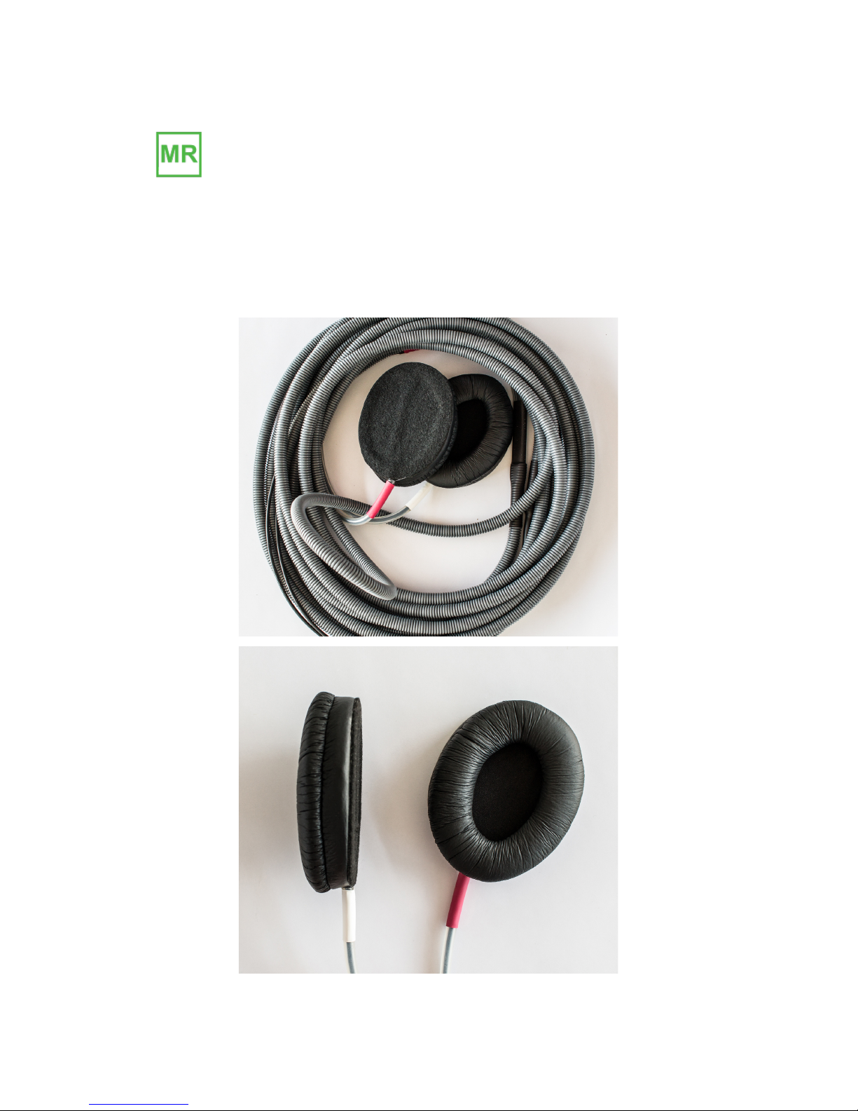
Headphones!................................................................................................................................................!5!
Amplifier!......................................................................................................................................................!7!
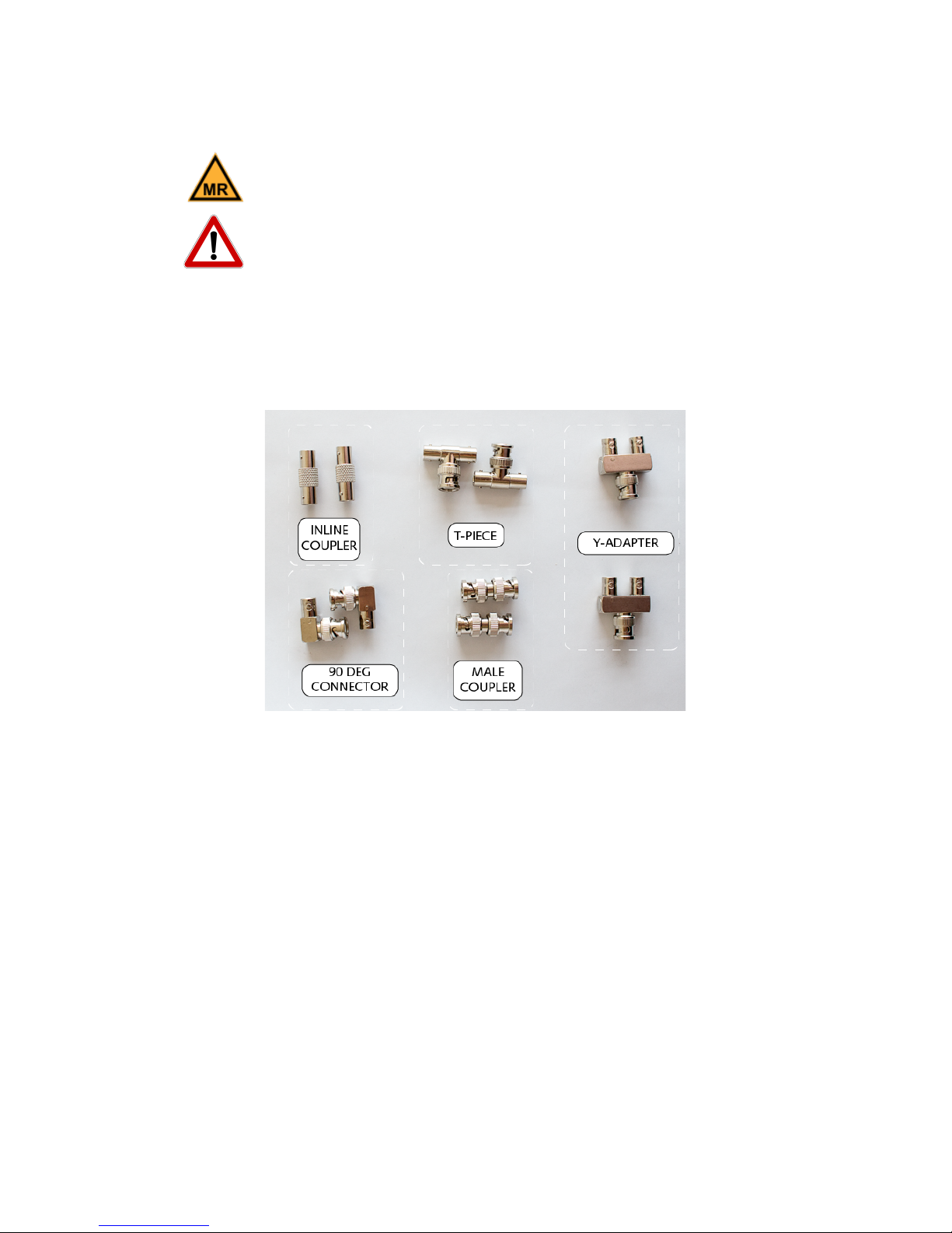
BNC!Connectors!........................................................................................................................................!8!
RF!Filter!Elements!...................................................................................................................................!9!
Technologist!Microphone!..................................................................................................................!10!
Filter!Box!...................................................................................................................................................!10!
Desktop!Speakers!..................................................................................................................................!11!
Analogue!to!Digital!Converter!.........................................................................................................!12!
Cables!.........................................................................................................................................................!13!
Memory!Foam!Cushions!.....................................................................................................................!15!
Control*Room*Assembly*........................................................................................................*16!
Starter!f!MKII+!Amplifier!Setup!......................................................................................................!16!
Connect!Headphone!Cable!................................................................................................................!16!
Connecting!to!the!Filter!Box!.............................................................................................................!17!
Connecting!the!Desktop!Monitor!Speakers!...............................................................................!18!
Connecting!the!Microphone!.............................................................................................................!20!
Connecting!Patient!Microphone!(optional)!...............................................................................!20!
Analogue!Audio!Setup!.........................................................................................................................!21!
AudioFile!Setup!......................................................................................................................................!22!
MRI*Room*Assembly*...............................................................................................................*24!
Headphones!.............................................................................................................................................!24!
Filter!Elements!.......................................................................................................................................!24!
Starter*f*MKII+*Amplifier*Quick*Reference*Sheet*.........................................................*26!
The!Amplifier!..........................................................................................................................................!26!
Technologist!Microphone!..................................................................................................................!28!
Getting!Started!........................................................................................................................................!29!
Safety*Warnings*........................................................................................................................*32!
Life!support!applications!...................................................................................................................!32!
Magnetic!fields!........................................................................................................................................!32!
Servicing!....................................................................................................................................................!32!
Cleaning*.......................................................................................................................................*32!
Dimensions*................................................................................................................................*33!
Safety*Conformance*................................................................................................................*33!
Contact*.........................................................................................................................................*33!