Electrified Locks, Relays and Timers
CX-DESPK15-54I and CX-DESPK15-55I External
15 Watt Speaker Station
INSTALLATION INSTRUCTIONS
THIS PACKAGE INCLUDES:
1 - Speaker Assembly
1 - Translucent/Black Trim
1 - Mounting Box Assembly
1 - Parts Kit
1. GENERAL DESCRIPTION
Camden Door Controls CX-DESPK15 15-watt speaker station is designed
for industrial and commercial applications, where both audio and visual
indication is required. The 15-watt speaker can provide amplied audio
messages where ambient noise may be present.
Note: only 12 VDC is provided for the amplied 15-watt speaker station.
Camden Aura™ PCB provides an added benet of an illuminated
enclosure. It oers eld selectable red/green/blue illumination, activated
directly by the switch or remotely by a relay* such as our CX-33 or EMF-2,
a time-clock or access control system. User selectable features include a 3
Amp Form ‘C’ relay, and piezo for audible annunciation, as well as control
over the idle and active LED colors. Another exclusive is the ability to plug
in a TX-9 RF transmitter, thereby requiring only 2 conductors be run for
power (no batteries required). The box is made of impact and ame-re-
sistant black ABS. The illumination is provided by an array of super-bright
and energy ecient LED’s, which can be powered by 12 or 24 volts AC/DC.
Page 1 of 4
2. APPLICATION
Camden remote speaker station is ideal for applications that require
a visual and audio capabilities such as a remote speaker station for
delayed egress locks, door chimes or paging systems. It can be surface
(CX-DESPK15-54i) or ush mounted(CX-DESPK15-55i). Camden remote
speaker station is designed to be wired to delayed egress maglocks, door
chimes and other low voltage systems..
3. SPECIFICATIONS
Voltage 8-24V DC, 5mA
Maximum Audio 15 Watt (82dB at 3 feet (0.9 m))
Output Impedance 8Ω
Voltage 12V or 24V AC/DC
Output Voltage 3 Volts DC for TX-9 (only)
Current Draw 250 mA @ 12V DC/110 mA @ 24V DC
Contact Rating 3A @ 30V DC
Lumina Red 14.8 lumens, 1600mW
AuraTM PCB
Lumina Green 3.8 lumens, 330mW
Sounder 3200 ± 300Hz @ 85 dB
Relay Contact 1 x Form C
4. FRONT AND SIDE (CX-DESPK15-54I)
PROPRIETARY AND CONFIDENTIAL
THE INFORMATION CONTAINED IN THIS
DRAWING IS THE SOLE PROPERTY OF
CAMDEN DOOR CONTROLS. ANY
REPRODUCTION IN PART OR AS A
WHOLE WITHOUT THE WRITTEN
PERMISSION OF CAMDEN DOOR
CONTROLS IS PROHIBITED.
5502 Timberlea Blvd.
Mississauga, ON Canada L4W 2T7
Tel: (905) 366-3377
www.camdencontrols.com
CX-DESPK15
2D Assembled
51
4''
[134mm] 21
4''
[58mm]
51
4''
5. FRONT AND SIDE (CX-DESPK15-55I)
65
8''
[168mm]
7
16''
[11mm]
1
13
16 ''
[46mm]
51
8''
[130mm]
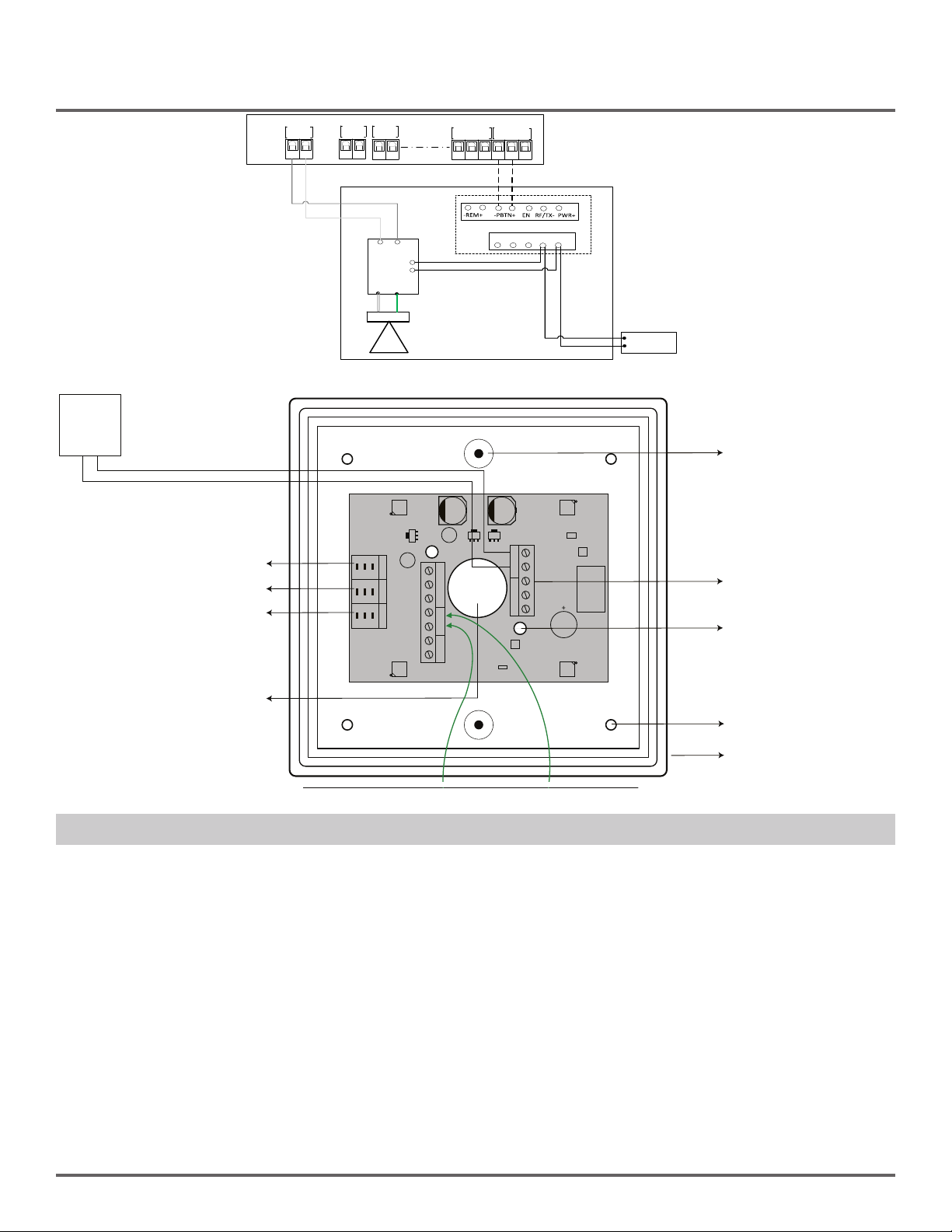
6. WIRING
Device Wire Color Connection
Speaker Green +Audio
White -Audio
Amplier Grey +Ex. Spk
White -Ex. Spk
Device Terminal Connection
Aura
AC/DC Common
PWR +12-24V AC or DC
- PBTN RED Rly C
+ PBTN RED Rly NO