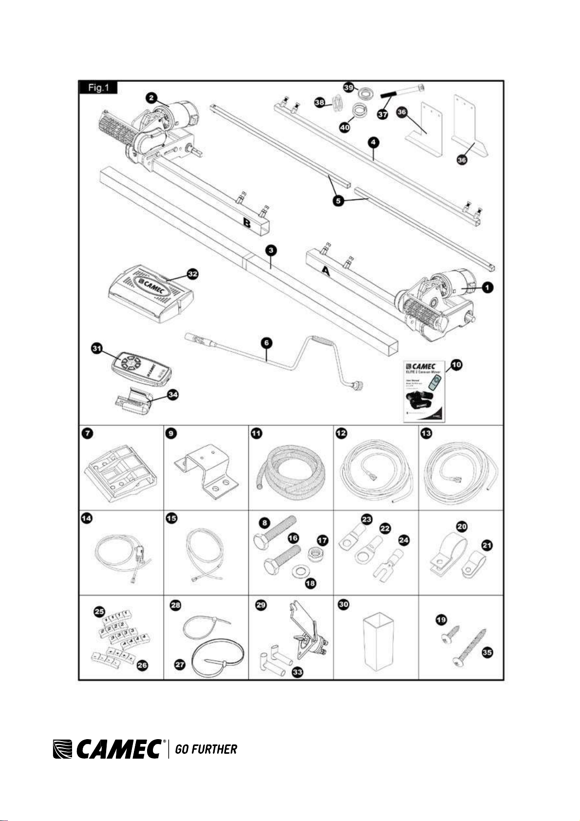
Camec ELITE 2 Caravan Mover User manual

ELITE®2 Caravan
Mover

3
CAMEC ELITE®2 EM303 Ref: ELITE 2 EM303-0715Rev.A.
Package contents (parts list)
Introduction
Intended use
Specifications
Installation - safety guidelines
Installation - mechanical components
Installation - electrical/electronic components
Installation - twin axle
Operation - safety guidelines
Operation - motor units
Operation - remote control handset
Operation - electronic control unit
Operation - getting started
Operation - hitching and unhitching
Maintenance
Troubleshooting
Page 3
Page 4
Page 4
Page 4
Page 5
Page 6
Page 8
Page 10
Page 12
Page 13
Page 14
Page 16
Page 17
Page 18
Page 18
Page 18
PACKAGE CONTENTS
Ref Qty Description
1 1 Motor unit (A) 2 1
Motor unit (B)
3 1 Main cross bar
4 1 Cross actuation centre bar
5 2 Cross actuation insert bars
6 1 Engagement tool
7 2 Aluminium chassis clamp plates (set)
8 4 Bolt - M10x60
9 2 Chassis U plate
10 1 Instruction manual
11 2 Convoluted cable trunking
12 2 Positive (+) red motor cable 5m
13 2 Negative (-) black motor cable 5m
14 1 Positive (+) red battery cable 1.8m including fuse holder & 80A fuse
15 1 Negative (-) black battery cable 1.6m
16 8 Bolt - M10x50
17 12 Nylon nut M10
18 24 Washer 10mmØ
19 20 Screw - M4x15
20 10 Cable trunking P-clips 19.2mm
21 10 Cable P-clips 10.4mm
22 4 Battery terminal connector 8mmØ
23 2 Battery terminal connector 6mmØ
24 4 Spade fork connector
25 3 Cable number markers (1,2,3,4)
26 3 Cable polarity markers (+,-)
27 4 Motor unit cable ties 8x400
28 10 Cable ties 2x70
29 1 Battery isolation switch, cover & key
30 2 Roller distance spacers 20x20
31 1 Remote control handset with lanyard
32 1 Electronic control unit
33 2 Rubber isolation shell for battery isolation switch
34 1 Remote control handset wall holder
35 2 Screw –M5x40
36 2 Chassis clamp plates (pair) with bolts M8x70, nuts and washers
37 6 Bolt - M8x70
38 6 Nylon nut M8
39 12 Washer 8mmØ
40 6 Spring washer 8mmØ

4
CAMEC ELITE®2 EM303 Ref: ELITE 2 EM303-0715Rev.A.
Package Contents

5
CAMEC ELITE®2 EM303 Ref: ELITE 2 EM303-0715Rev.A.
INTRODUCTION
Congratulations on choosing the Camec Elite®2 EM303 caravan manoeuvring system. This has been produced
according to very high standards and has undergone careful quality control procedures.
By using the remote control handset you can move your caravan effortlessly into any position required within
operating guidelines. Soft start and soft stop technology allows you to manoeuvre your caravan accurately without
any shocks.
The caravan manoeuvring system consists of two 12V motor-power rollers, a 12V electronic control unit and a
remote control handset. To function, the motor-powered rollers must be engaged against the tyres of your caravan.
The supplied cross actuation device enables you to engage both rollers at the same time from one side of your
caravan. Once this is done, the manoeuvring system is ready for operation. The remote control will allow you to
move your caravan in any direction. You can even rotate the caravan on its own axis, (function not compatible with
double axle caravans) without moving forwards or backwards.
Before proceeding with installation and starting to use the manoeuvring system, please read
this manual very carefully and be aware of all the safety instructions! The owner of the caravan
will always be responsible for correct use. Keep this manual inside your caravan for future
reference.
INTENDED USE
The Camec Elite®2 EM303 caravan manoeuvring system is suitable for single axle and double axle caravans.
Suitableonly for L-profiled and U-profiled chassis with a chassis thickness
betweenmin. 2.8mm and max.
3.5mm.
Depending on the weight of the caravan, the manoeuvring system cannot overcome obstructions that are more
than about 2cm in height without assistance (please use wedges as a ramp).
The standard installation kit only provides parts for installing the caravan manoeuvring system within the
measurements given in Fig. 2.
SPECIFICATIONS
Designation
Camec Elite®2 EM303
Operational voltage
12 Volt DC
Average current consumption
20 Ampere
Maximum current consumption
100 Ampere
Speed
approx. 9cm per sec.
Weight (2 motor set)
approx. 37kg (excludes battery)
Permissible overall Weight single axle (2 motors)
1800kg (1500kg on 18% gradient)
Permissible overall Weight double axle (2 motors)
1800kg (1500kg on 18% gradient)
Permissible overall Weight double axle (4 motors)
2500kg (1800kg on 18% gradient)
Minimum width (caravan/trailer)
1800mm
Maximum width (caravan/trailer)
2500mm
Maximum tyre width
205mm
Power source (battery)
LiFePO4: 12V, 20Ah (recommended Camec Elite®2
EM303) Lead acid: 12V, 80Ah (min.)

6
CAMEC ELITE®2 EM303 Ref: ELITE 2 EM303-0715Rev.A.
INSTALLATION - SAFETY GUIDELINES
Read this user manual carefully before installation and use. Failure to comply with these rules
could result in serious injury or damage to property.
These symbols identify important safety precautions. They mean CAUTION! WARNING!
SAFETY FIRST! IMPORTANT INFORMATION!
Before starting installation under the caravan:
•Check the towing load of your vehicle and the gross weight of your caravan in order to establish whether they
are designed for the additional weight. The manoeuvring system itself has a weight of about 37kg and a battery
has a weight of about 20-25kg.
•Check the minimal installation dimensions of the manoeuvring system
based on figure 2.
•Check that the caravan is disconnected from the battery supply and the mains electrical supply.
•Only use adapters and accessories that are supplied or recommended by the manufacturer.
•Check that the tyres are not worn and do have the same size
and design (fitting to new or nearly new tyres is the best option).
•Make sure that the tyre-pressures are correct to the manufacturer’s recommendation.
•Make sure the chassis is in good condition without any damage and is free from rust, dirt etc.
•Stop work immediately if you are in doubt about the assembly or any procedures and consult one of our
engineers (please refer to contact information on the last page of this manual).
•Locate the battery isolation switch. It must be accessible at all times when parking and moving the caravan.
•Do not remove, change or alter any parts of the chassis, axle, suspension or brake mechanism. Any drilling of
holes in the chassis is not allowed.
•Do not install the unit if you are under the influence of
drugs, alcohol or medication that could impair your ability to use the
equipment safely.
INSTALLATION - MECHANICAL COMPONENTS
FOR PROFESSIONAL INSTALLATION ONLY. These instructions are for general guidance.
Installation procedures may vary depending on caravan type.
Working under a vehicle without appropriate support is extremely dangerous!
Please refer to figure 3 for an overview of the whole assembly fully fitted.
Fig. 2

7
CAMEC ELITE®2 EM303 Ref: ELITE 2 EM303-0715Rev.A.
•Place the caravan on a hard, level surface. The use of a
lifting ramp or an assembly pit is ideal for access and
personal safety.
•Unpack all the components and check for the presence of all
parts (see package contents list pg. 2). Write down, on the
product warranty registration card, the 10-digit serial number
(this is located on an aluminium plate on the side of one of
the motor units).
•Clean the area of your chassis where you need to mount all
components to ensure a good fitting.
•Make sure the caravan is prepared for installation. Check
before installation that important areas, such as drains/spare
tyre, etc. do not cause any obstruction to the function of the
caravan manoeuvring system. • Ensure both rollers
are in the DISENGAGED position (Fig. 5A), as the
unit will not fit correctlyotherwise
(Note: when fully disengaged, the pointer is
positioned in the beginning of the yellow area).
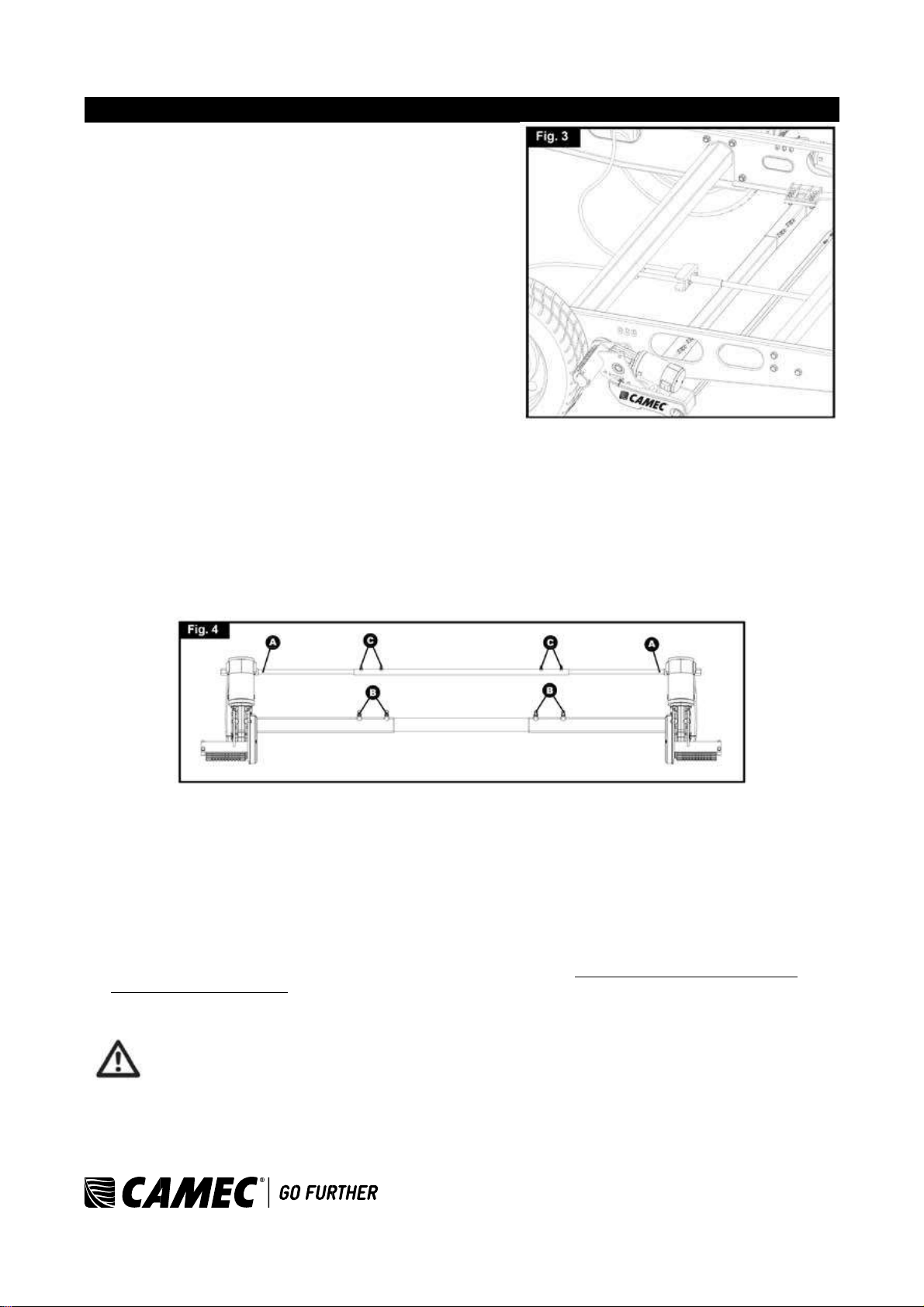
•Loosely assemble the left hand motor unit (1), right hand motor unit (2) and main cross bar (3) (Fig. 4). The
nuts (Fig. 4B), on the cross bar (3) to secure both motor units,
must be no more than finger-tight at this stage.
Note: In principle, the unit should be fitted in front of the
caravan road wheels, but if fitting in this position is not possible
becauseof obstacles or a too high hitch ball weight, it is
permissible to fit it to the rear of the wheels by
rotating the whole assembly (Fig. 4) by 180° degrees.
•Fit the Chassis Clamp Plates (36) to the chassis using bolts (37),nuts (38), washers (39) and spring washers
(40), then loosely fit the two aluminium clamp plates (7) to the
plates (36) (Fig. 6 & 3) and attach. Use the bolts M10x60,
nuts M10 and washers M10 (8,17,18) and put them in the diagonal positioned holes of the aluminium chassis
clamp plates. Nuts must be no more than finger-tight.
•Assemble the pre-mounted manoeuvring system on the aluminium chassis clamp plates (7) by using the two U-
shaped brackets (9), bolts M10x50, nuts M10 and washers M10 (16,17,18). Nuts must be no more than finger-
tight.
•Make sure that aluminium drive rollers of the motors are approximately on the same altitude as the centre
(axle) of the caravan wheel (± 20mm). To compensate a possible unevenness (and lower the motors), Camec
Elite®2 has a set of distance plates available. One set can compensate 15mm. In total three sets can be used
so that an altitude of 45mm can be compensated.
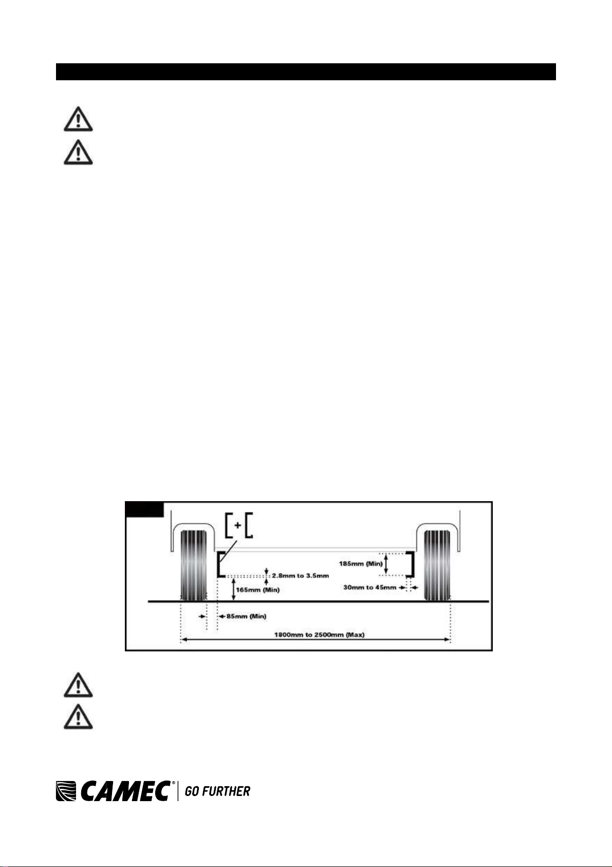
Adequate ground clearance: Please notice that the min. distance between the lowest line of
motors and ground is 110mm, no matter what kinds chassis or install situation.

8
CAMEC ELITE®2 EM303 Ref: ELITE 2 EM303-0715Rev.A.
•Assemble the parts of the cross actuation bar
(4 & 5) and connect them to the motor units
(1 & 2) with the nylon nut and bolt (factory
fitted) onto the cross
actuation bar-connectors (Fig. 4
& Fig. 4A). Nuts must be no more than
finger-tight at this stage.
•Make sure that the main cross bar (12) and
the cross actuation centre bar (4) are
positioned in the middle of the caravan (the
centre of the bar is marked).
•When the main assembly
is loosely fitted onto the
chassis, slide the whole assembly along the
chassis until the rollers are 20mm away from the surface of the centre each tyre (Fig. 5). Two 20mm spacers
(30) are provided.
It is vitally important that each roller is at exactly the same distance away from the tyre. The
whole assembly must be parallel to the caravan/trailer axle.
Slide the motor units in or out of the cross bar (3) accordingly to ensure the roller will have the
maximum possible contact with the tread of the tyre. Ensure that the position of each motor
unit does not obstruct shock absorbers (if fitted) and that the gear cover (Fig. 7) is not too close
to the surface of the tyre/shock absorber. The minimum clearance when the drive units
swivelled in is 10mm.
•Fully tighten the four bolts (Fig. 4B) on the
main cross bar (3) and the four bolts (Fig.
4C) on cross actuation assembly (4 & 5).
•Fully tighten all the nylon nuts on both
clamping assemblies (Fig. 6). First tighten
the diagonal placed M10x60 bolts with a
20Nm torque, and then M10x50 bolts to a
40Nm torque.
•Re-check the distance of 20mm from the
rollers to the tyres, the position of the
aluminium rollers in addition to the surface
of the tyre and finally the
distancebetweenthe plastic gear cover
(Fig. 7) and the tyres & shock absorbers
(>10mm). The weight of the caravan musty
be on the wheels when doing this. If
necessary, loosen the bolts and re-adjust
the position of the assembly.
The main mechanical components have now
been installed.

9
CAMEC ELITE®2 EM303 Ref: ELITE 2 EM303-0715Rev.A.
Re-check that all bolts/nuts have been tightened to the correct torque!
INSTALLATION - ELECTRICAL/ELECTRONIC COMPONENTS
Make sure the 12V supply from the battery and any 240V electricity supply are disconnected.
•Remove battery cable terminals and disconnect any external electrical power before starting work.
•Find a suitable place for the electronic control unit (32), such as a storage area, under a seat or a bed. Make
sure this place is dry and close to the battery (40cm to 60cm). The electronic control unit can be mounted
vertically on a side wall or be mounted flat. When mounted
vertically, the connections must point downwards to avoid any
short-circuits by objects falling into it.
•Fix the electronic control unit securely into position with two screws M5x40 (35). Note: if the provided screws
are not of suitable length or type for the desired location/material, please substitute these as appropriate. • Drill
a 25mm hole through the floor of the caravan approximately 150mm
centrallyin front of the control unit (32) terminals.
Caution! Take extra care to avoid any chassis members, gas pipes and electrical wires!
•Route and connect the motor-cables in accordance with wiring diagram (Fig. 8) (red = positive, black =
negative). The wiring diagram (Fig. 8 + Table. A) below depicts the wiring route when installing the motor units
in front of the wheels/axle towards the ‘A’ frame. Please refer to table B
(below) for fitment of the motor units to the rear of the
axle.
Table A
Table B
FRONT OF AXLE FITTING
REAR OF AXLE FITTING
Motor A Positive (+) cable to terminal 4
Motor A Positive (+) cable to terminal 1
Motor A Negative (-) cable to terminal 3
Motor A Negative (-) cable to terminal 2
Motor B Positive (+) cable to terminal 2
Motor B Positive (+) cable to terminal 3

10
CAMEC ELITE®2 EM303 Ref: ELITE 2 EM303-0715Rev.A.
Motor B Negative (-) cable to terminal 1
Motor B Negative (-) cable to terminal 4
•Mark the motor cables (12 & 13) for both motor units using the cable markers (25). The cables for the left and
the right motor should have the same length. Avoid any loops.
•Connect the spade connectors to the motors. Please note that the red cable is connected to the terminal under
the moulded ‘+’ symbol on the weatherproof terminal cover.
•Use the large cable ties (27) to secure the motor cables to the motor. This ensures that there is no force and
movement on the spade connectors or movement of the cables during transit.
Remember to leave a small amount of slack cable near the motors to allow for their movement when the drive
rollers are engaged. • Route the motor cables along the underside of the
caravan floor, inside the suppliedconvoluted trunking (11) (this will protect the
electrical cables against sharp edges and dirt) and through the drilled hole.
•Secure the cable trunking (11) to the chassis or under body of the caravan by using the P-Clips (20) and
screws
(19).
•Once the motor cables are through the drilled hole next to the control unit (32), cut the cables, ensuring that
they are same length. Remove approx. 5mm of the insulation from the ends.
•Fix the spade fork connectors (24) to the motor cables by using crimping pliers. A secure and good quality
connection on each cable is essential.
•Attach the spade fork connectors to the terminals on the
control unit (see wiring diagramFig. 8) and fix them tightly by the
screws. A safe and good quality connection on each cable is essential.
•Find a suitable place for the battery power isolation switch (29) which includes an external holder with hinged
cover. Important: The switch must be mounted onto the exterior body of the caravan and be easily
accessible from the outside of the caravan in case of any emergency. The switch must be mounted close
to the location of the battery in order to keep the length of the battery cables to a minimum.
•Use the cardboard template to position the hole positions and the drill holes. Mount the switch and the housing
with the bolts, washersand nuts, and finally mount it on the caravan with
stainless steel screws (19).
•Route the positive (+) power cable (including fuse) from the battery to the battery power isolation switch (29)
and then further to the control unit (32).
The electronic connections of the battery power isolation switch (29) must be covered by the supplied rubber
isolation shells (33).
•Route the negative (-) power cable directly to the control unit (32).
No cables may be routed over the control unit!
It is recommended to use the supplied trunking (11) to protect the cables against sharp edges.
•Attach the trunking with P-clips (20) and P-clip screws (19).
•Cut the cables to an appropriate length and remove approx. 5mm of the insulation from the ends.
•Fix the spade connectors by using crimping pliers. Two types of battery terminal connector (22 & 23) are
provided for use as appropriate. A secure and good quality connection on each cable is essential.
•Connect the battery cables (14 & 15) to the control unit (32): Attach the spade fork connectors to the positive
(+) and negative(-) terminal of the control box and fix them tightly by
the screws.
•Connect the battery cables to the existing battery terminals (red = positive, black = negative).

11
CAMEC ELITE®2 EM303 Ref: ELITE 2 EM303-0715Rev.A.
Caution! Make sure that you do not reverse the Positive (+) and Negative (-) connections.
Incorrect connection (reverse polarity) will result in damage to the control unit.
•Seal the 25mm hole in vehicle under body using plastic body sealant.
•Finally find a suitable place for the remote control handset wall holder (34)
and fix this by the suppliedscrews (out
of reach of children or other unauthorised people).
Installation of the caravan manoeuvring system is now complete.
INSTALLATION - TWIN AXLE
When you use the manoeuvring system for a twin axle caravan, please check the following:
Permissible overall weight twin axle (2 motors) 2000kg (1750kg on 18% gradient)
Permissible overall weight twin axle (4 motors) 3000kg (2350kg on 18% gradient)
2 motors:
The procedure for installing a 2 motor manoeuvring system
on a twin axle caravan is the same as for a single axle
caravan. The electronic control unit (4) only must be
prepared for twin axle use. Turn off the battery power
isolation switch and move the single/twin axle function switch
(Fig 9S/T) on the control unit to the twin axle position (Fig.
9T), so that the manoeuvring system can be used for a twin
axle caravan. In the twin axle function when making curves,
all wheels will drive but, at a different speed.
4 motors:
The procedure for installing a 4 motors manoeuvring system
on a twin axle caravan is similar to a single axle caravan but
with two sets of manoeuvring systems.
Follow the procedure INSTALLATION - MECHANICAL COMPONENTS twice: one time for the manoeuvring set
mounted in front of the twin axle and one time for the manoeuvring set mounted behind the twin axle.
Follow the procedure INSTALLATION - ELECTRICAL/ELECTRONIC COMPONENTS twice: one time for the
manoeuvring set mounted in front of the twin axle and one time for the manoeuvring set mounted behind the twin
axle (see wiring diagram pg. 11).
Note: When installing the four motors it will be necessary to use one higher capacity battery to supply both sets of
manoeuvring system (including two electronic control units and two battery power isolation switches). Do not use
two separate batteries for a 4 motors manoeuvring system on a twin axle caravan.
Now both electronic control units (4) must be prepared for twin axle use:
•Turn off the battery power isolation switch and move the single/twin axle function switch (Fig 9S/T) on the
control unit to the twin axle position (Fig. 9T), so that the manoeuvring system can be used for a twin axle
caravan. In the twin axle function when making curves, all wheels will drive, but at a different speed.
Finally both electronic control units (4) must be prepared for the use of only one remote handset (32). The remote
handset need to be synchronised with both electronic control units using the following procedure:
•Check the installation in accordance with the installation instructions and ensure that the drive rollers are not
applied. Check that the battery is properly connected, check the condition of the battery and that a voltage of
12V is present at the control unit.
•Please ensure that both battery isolation switches are on.

12
CAMEC ELITE®2 EM303 Ref: ELITE 2 EM303-0715Rev.A.
•Activate the remote control handset by sliding the slide switch to “On”-I (Fig.
10A). The green LED on the remote control handset (Fig. 10H) will start to
flash slowly.
•Press the reset button (Fig. 9A) on the control unit. All three LED’s on the
control unit (Fig. 9B, 9C & 9D) will
flash slowly.
•Press both the forwards (Fig. 10B) and reverse (Fig. 10C) button on the
remote control handset for about 3 seconds. The handset buzzer will give a
short beep to confirm that the synchronisation is
complete.
•After successful synchronisation, the green LED on the control unit (Fig. 9B)
and on the remote control handset (Fig. 10H) will illuminate continuously.
•Repeat this procedure with the second electronic control unit.
•Turn the remote handset “Off” and then “On” again so both control units will be activated.
The installation of the caravan manoeuvring system for twin axle use is now complete. For details of the operation,
use and all the LED and button functions, please refer to the table of contents.

13
CAMEC ELITE®2 EM303 Ref: ELITE 2 EM303-0715Rev.A.
Diagram for 4 x 4 montering.

14
CAMEC ELITE®2 EM303 Ref: ELITE 2 EM303-0715Rev.A.
OPERATION - SAFETY GUIDELINES
Practiceoperating the manoeuvring system in an open area before using for
the first time to fully familiarise yourself with the handset/manoeuvring system
operation.
Before use, always check the caravan manoeuvring system for any damage.
When towing or moving the caravan please be aware, at all times, that ground clearance is reduced when
the manoeuvring system has been fitted.
Always ensure that children and pets are kept well out of the way during operation.
When operating the system, ensure that no hair, fingers or other
body parts, clothing or any other objects carried on the body can become
trapped by moving or rotating parts (e.g. drive rollers).
In the event of malfunctions, pull on the handbrake immediately and turn off the main isolation power
switch.
To maintain signal strength, always make sure that, during manoeuvring, the distance between the remote
control and the caravan does not exceed 5 metres.
Due to the nature of a radio signal, it can get corrupted by external terrain or objects. So there may be
small areas around the caravan where the quality of reception reduces, hence the manoeuvring system
may stop momentarily.
Always be aware that the manoeuvring system increases the weight of your caravan or trailer. So this
reduces the payload of the caravan.
Do not exceed the total safe working load of 1800kg laden weight (caravan including load) when 2 motors
are used and 2500kg laden weight (caravan including load) when 4 motors (twin axle) are used.
Always make sure that the rollers are fully disengaged from the tyres when the manoeuvring system is not
in use. This is better for the tyres and for the system.
Always make sure that the rollers are fully disengaged before towing/moving the caravan by vehicle or
manpower. This can damage the tyres, manoeuvring system and the towing vehicle.
Always make sure that after you have finished using the manoeuvring
system, the battery power isolationswitch (29) is switched off and the key is removed and
stored in a safe place (out of reach of children or other unauthorised people). If you don’t switch off, the battery will
be discharged by the small ”standby” current.
Always make sure that the remote control handset is switched off and stored (in the wall holder) in a safe
place (out of reach of children or other unauthorised people). If you don’t switch off, the battery will be
discharged by the small ”standby” current.
Do not rely on the manoeuvring system to act as a brake.
Always apply the handbrake after manoeuvring, before disengaging the drive rollers from the tyres.
Do not use the manoeuvring system as a support when jacking up the caravan, since this can damage the
drive unit.
Depending on the weight of the caravan, the manoeuvring system cannot overcome all obstructions
without assistance. Please use wedges as a ramp.
All wheels and tyres on the caravan must be of the same size and design. If tyres are worn or new tyres
are fitted, the distancebetweenthe drive rollers and the tyres may
need readjusting (see “Installation - Mechanical Components”).

15
CAMEC ELITE®2 EM303 Ref: ELITE 2 EM303-0715Rev.A.
Sensitive objects such as cameras, DVD-Players etc. must not be kept in the stowage box near the
control unit or the motor cable. They can be damaged by the
electromagnetic fields.
Do not make any modifications on the caravan manoeuvring system
(mechanical or electronically). This can be very dangerous! No warranty claim will
be accepted and we cannot guarantee the function of the system if any modifications are
made. We will not be liable for any damagewhatsoever caused as
a result of incorrect installation, operation or modification.
OPERATION - MOTOR UNITS
The manoeuvring system has two motor units (1 & 2). In general they are mounted in front of the axle of the
caravan. Both units are identical but cannot be switched.
A.
Aluminium drive roller
B.
12V motor
C.
Connection terminals (+ and -)
D.
Base unit
E.
Drive unit
F.
Gear cover
G.
Spindle
In order to engage the rollers, fit the end socket of the engagement
tool (6) on the spindle (G) (Fig. 11) on the right or left
drive unit and turn the handle (Fig. 12 and 13).
Traction indicator label:
The yellow-green-red traction indicator label (Fig. 14A), on the side of each motor unit indicates if the roller is
depressing the tyre sufficiently to provide adequate traction.
If the pointer is in the
YELLOW area
Rollers are not touching or
depressing the tyre
sufficiently
If the pointer is in the
GREEN area
Rollers should be connecting
correctly to the tyre (margin of
15mm)

16
CAMEC ELITE®2 EM303 Ref: ELITE 2 EM303-0715Rev.A.
If the pointer is in the
RED area
Rollers are connected to the
tyre but in an extreme
position. It could be that the
tyre of the caravan has
insufficient air
pressure or the drive
unit has been knocked out of
position and a visit to a
workshop is
required to reposition the
assembly
OPERATION - REMOTE CONTROL HANDSET
The remote control handset (31) is powered by one PP3 9 Volt battery, and is activated by moving the slide
switch to “On”-I (Fig. 15A). Once activated the green LED (Fig. 15H) will illuminate and the directional controls
can now be used.
A.
Slide switch (“Off” –O and “On”-I)
B.
Caravan forwards
(both wheels rotate in forwards direction)
C.
Caravan reverse
(both wheels rotate in reverse direction)
D.
Caravan left forwards
(right wheel rotates in forwards direction)
E.
Caravan right forwards
(left wheel rotates in forwards direction)
F.
Caravan left reverse
(right wheel rotates in reverse direction)
G.
Caravan right reverse
(left wheel rotates in reverse direction)
H.
Green LED: Reflectsstatus of the remote
control and caravan manoeuvring system
I.
Red overload LED: Amp overload protection is activated. Wait
about 60 seconds and try again
J.
Blue 9V battery LED: The internal 9V battery of handset is
near empty and needs to be replaced
K.
Blue battery voltage LED: Caravan battery voltage too low or
too high
When you drive straight forwards or reverse (press button B or C), it is also possible to adjust the direction by
additionally pressing button D or E (when driving forwards), or button F or G (when driving reverse).
In addition, the ‘right forward’ (E) and ‘left reverse’ (F) buttons, or ‘left forward’ (D) and ‘right reverse’ (G) buttons
may be pressed at the same time to turn the caravan around on its own axis without moving forward or backward
(single axle setups only).
When you switch within 2 seconds from forward driving to reverse driving (and the other way around), a small delay
of 1 second will occur to protect the electronics and the motors.
The slide switch (Fig. 15A) also acts as an “Emergency stop”.
The remote hand set switches off:

17
CAMEC ELITE®2 EM303 Ref: ELITE 2 EM303-0715Rev.A.
•After 3 minutes, if no button is pressed: After 2 minutes the buzzer will beep 5 times with a repetition after 3
minutes. Then the system switches to “stand-by” mode.
•After 6 minutes, if one of the movement buttons is permanently held down: After 5 minutes the buzzer will beep
5 times with a repetition after 6 minutes. Then the system switches to “stand-by” mode.
When the remote handset is in “stand-by” mode, it may still draw some current. Be sure to slide the switch to “Off” –
O to preserve the battery.
To reactivate the remote control, move slide switch to “Off” –O and then back to “On”-I after approximately 1
second.
Error messages via the remote control handset:
Error messages of the Camec Elite®2 EM303 manoeuvring system will be communicated via the remote control
handset by the green LED (Fig. 15H), the error message LED’s (Fig. 15I, 15J & 15K) and a buzzer signal.
Green LED (Fig. 15H) off, no buzzer:
Remote control handset is turned off and system is not
activated.
Green LED (Fig. 15H) continuously on, no buzzer:
Remote control handset is on and system is activate and
ready to use.
Green LED (Fig. 15H) is blinking, no buzzer:
No communication between handset and control unit. This
could be because of too much distance between remote
control handset and control unit, or the battery isolation
switch for the manoeuvring system is not turned on or, that
there is a distortion signal disturbing the communication. As
soon as connection is good again the green LED will be
continuously on and the system is ready to use.
Blue battery voltage LED (Fig. 15K) is blinking in
combination with buzzer (2 times blinking, break, 2
times blinking, break etc.):
Battery voltage too low (<10V). Battery needs to be
recharged.
Blue battery voltage LED (Fig. 15K) is blinking in
combination with buzzer (4 times blinking, break, 4
times blinking, break etc.):
Battery voltage too high (over charged). Try to discharge the
battery by turning on an appliance (for example a lamp or
water-pump).
Red overload LED (Fig. 15I) is blinking in
combination with buzzer (6 times blinking, break, 6
times blinking, break etc.):
Amp overload protection is activated. Wait about 60 seconds
and try again.
Blue 9V battery LED (Fig. 15J) is blinking, no
buzzer:
The internal 9V battery is near empty and needs to be
replaced.

18
CAMEC ELITE®2 EM303 Ref: ELITE 2 EM303-0715Rev.A.
Changing batteries in the remote control:
When the battery is empty (blue 9V battery LED (Fig. 15J)
is blinking), it needs
Open the rear cover of the handset (Fig. 16A).
Take out the dead/old battery and dispose in the appropriate
way.
Install a new replacement battery (Fig. 16.1). Make sure to
use a leak proof PP3 (9Volt) battery (no claims under
guarantee can be considered for damage caused by
leaking batteries).
Close the rear cover again.
Dead and used batteries may leak and damage the
remote control handset! Remove the batteries if the
handset is not going to be used for an extended period.
OPERATION - ELECTRONIC CONTROL UNIT
The electronic control unit (32), which is mounted
inside your caravan, is responsible for controlling the
manoeuvring system.
The control unit has three LED’s, one push button and
one slide switch (Fig. 17):
Green LED (Fig. 17B)
Power LED continuously illuminated
when system is activated (by moving
slide switch to “On”-I).
If the handset is far away from the control unit,
beyond the connection distance, this LED will go
out.
Blue LED (Fig. 17C)
Error message LED
concerning caravan
battery
Blue LED is blinking (2 times blinking,
break, 2 times blinking, break etc.)
Battery voltage too low (<10V). Battery needs to
be recharged.
Blue LED is blinking (4 times blinking,
break, 4 times blinking, break etc.)
Battery voltage too high (over charged). Try to
discharge the battery by turning on an appliance
(e.g. a lamp or water-pump).
Red LED (Fig. 17D)
Red LED is blinking (6 times blinking,
break, 6 times blinking, break etc.):
Amp overload protection is activated. Wait about
60 seconds and try again.
In general all error messages will reset automatically after one minute. If this is not the case, reset the electronics of
the manoeuvring system by switching off the system via the isolation switch and the remote control handset for at
least 15 seconds and then turning it on again.
The Reset Button (Fig. 17A): The remote control handset and the control unit are synchronised with each other in
the factory. If the control unit or the remote control handset is replaced, they must be re-synchronised as described
below:
to be replaced.
•
•
•
•

19
CAMEC ELITE®2 EM303 Ref: ELITE 2 EM303-0715Rev.A.
•Check the installation in accordance with the installation instructions
and ensure that the drive rollers are not applied. Check that the battery
is properly connected, check the condition of the battery and that a
voltage of 12V is present at the control unit.
•Please ensure that the battery isolation switch is on.
•Activate the remote control handset by sliding the slide switch to “On”-I
(Fig. 18A). The green LED on the remote control handset (Fig. 18H)
will start to flash slowly.
•Press the reset button (Fig. 17A) on the control unit. All three LED’s on
the control unit (Fig. 17B, 17C & 17D) will
flash slowly.
•Press both forwards (Fig. 18B) and reverse (Fig. 18C) button on the
remote control handset for about 3 seconds. The handset buzzer will
givea short beep to confirm that the
synchronisation is complete.
•After successful synchronisation, the green LED on the control unit (Fig. 17B) and on the remote control
handset (Fig. 18H) will illuminate continuously.
The single-twin axle function switch (Fig. 17S/T): The Camec Elite®2 EM303 caravan manoeuvring system is
suitable for both single axle and twin axle caravans. You just need to move the single-twin axle function switch
(Fig 17S/T) on the control unit, so that the manoeuvring system can be used for a single-axle caravan or a twin-
axle caravan (for 2 motor use but also for 4 motor use). In the twin axle function, all wheels will drive, but at a
different speed.
The switch is pre-selected for single axle use (Fig. 17S): For twin axle use, just move the switch to the twin axle
position (Fig. 17T). When move the single-twin axle function switch, the battery power isolation switch (29) must be
turned off.

20
CAMEC ELITE®2 EM303 Ref: ELITE 2 EM303-0715Rev.A.
OPERATION - GETTING STARTED
Please make sure you read the safety
instructions very carefully and make sure
that you follow these guidelines!
Make sure that the battery that supplies the
system is fully charged and in good
condition.
Make sure that the caravan is free from the
vehicle and the handbrake is on. Also make sure that the
corner steady feet are fully raised.
•Fit the end socket of the engagement tool (7) onto the
engagement spindle (Fig. 19) on the right or left hand
motor unit. This only needs to be done on one side of
your caravan since the other side will automatically follow
via the cross actuation bar.
•Turn the handle until it will turn no more without
excessive force. The colour of the traction indicator label
(Fig.20A) should be in the green area.
•Turn on the battery power isolation switch (29).
•Before operating the manoeuvring system, release the
handbrake.
•Activate the manoeuvring system by move slide switch to
“On”-I on the remote control (Fig. 21A). The green LED (Fig. 21H) on the remote control handset will illuminate
and you will hear a short beep. The remote control is ready for use.
Now you can choose the movements according the symbols shown on the
remote control:
In addition, the left forward (Fig. 21D) and right reverse (Fig. 21G) buttons or right
forward (Fig. 21E) and left reverse (Fig. 21F) buttons may be pressed at the
same time to turn the caravan around on its own axis without moving forward or
backward.
When you drive straight forwards or reverse (press button 21B or 21C), it is also
possible to adjust the direction by additionally pressing button 21D or 21E (when
driving forwards) or button 21F or 21G (when driving reverse). Because of the “soft start” technology, the caravan
will slowly speed up. Because of the “soft stop” technology, the caravan will stop slowly. This allows you to
manoeuvre your caravan even more accurately without any shocks.
WARNING: When the buttons on the remote control handset are released, the caravan will
slowly
stop after 0.5 second and continue to move about 6cm (depending on final speed). When the
buttons of the remote control handset are released when the system is still in the “soft start”
stage (slowly speed up), the caravan will stop immediately.
After the “soft start” stage the caravan moves accordingly one fixed speed. The
speed can increasea little when going downhill and decrease a little when going
uphill. TIP: The manoeuvring system is more efficient when reversing the
caravan up an incline.
•After manoeuvring, deactivate the manoeuvring system by moving the slide switch to “Off”-O on the remote
control handset (Fig. 21A). The green LED (Fig. 21H) on the remote control handset will turn off. Store remote
control in a safe place (out of reach of children or other unauthorised people).
Straight forward (Fig.
21B)
Left forward (Fig.
21D)
Right forward (Fig.
21E)
Straight reverse (Fig.
21C)
Left reverse (Fig.
21F)
Right reverse (Fig.
21G)
This manual suits for next models
1
Table of contents