All information contained herein is strictly confidential APPEB1006 User Manual rev1.0, 31-May-2005 page 3 of 6
© CAP-XX Pty Limited 2005
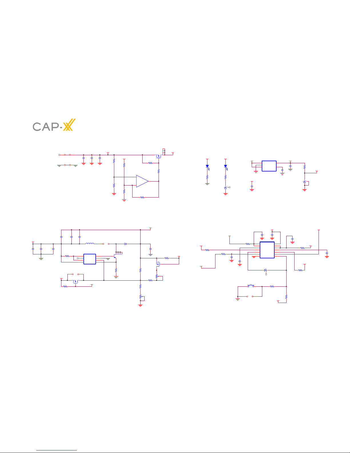
Boost Converter
J2 needs to be jumpered for normal operation. This jumper has been included so a wire loop
can easily be inserted to measure the inductor current. By measuring the inductor current
and monitoring the base drive voltage of Q1 the current through Q1, D3 and supercap can
also be determined.
J4 is not jumpered during normal operation. This jumper has been included to manually
disable the boost if required. If jumpered it forces the feedback voltage at pin 6 of the boost
to be 3V which is >> than the 730mV of the internal reference thereby instructing the boost to
cease switching.
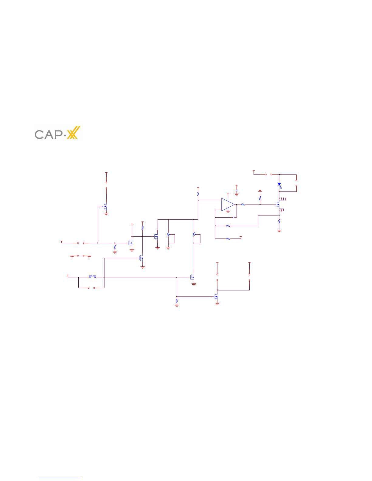
The boost can also be disabled by pulling the gate of M3 low. This can be done automatically
during a FLASH pulse by jumpering J7 or while in TORCH mode by jumpering J10.
The advantage of disabling the boost during a FLASH pulse is that the maximum battery
current is equal to the load (flash LED) current, however, the disadvantage is that the
supercap discharge current is also equal to the load current and it will discharge at a faster
rate than if the boost was enabled. The disadvantage of enabling the boost during a Flash
pulse is that the maximum battery current is greater or much greater then the load current
depending on the current limit set on the boost.
FLASH MODE
The boost generates an output voltage (Vout) that is > the battery voltage. For FLASH mode,
Vout is factory set to 5.7V. This voltage can be increased by turning R17 (a 2k pot)
anticlockwise. Care must be taken if this voltage is increased not to overvoltage the
supercap, ie the supercap voltage will be Vout minus the voltage of the battery. For
maximum supercapacitor life the voltage should be kept below 2.3V however short term
overvoltages (seconds) may go up to 2.7V.
TORCH MODE
The continuous current required for TORCH is << FLASH current (typically 100mA Vs 1A).
Therefore the voltage dropped across the LED will be less. To increase efficiency (and to
reduce thermal stress on the current limiting MOSFET (M4)) Vout should also be reduced.
There are two options for the TORCH Vout, if constant high output light is more important
than efficiency then option a) should be chosen.
a) In this option the Boost is enabled with J10 removed and J11 is jumpered. Vout can
be adjusted using R12 (a 500k pot). Vout is factory set to 4.2V. This means that Vout
will always be > Vin irrespective of the battery voltage. In this mode the forward
voltage to drive the LED at 200mA, for example, will always be available even when
the battery nears its end voltage (3.3V).
b) In this option the Boost is disabled with J10 jumpered and J11 is don’t care. This
means Vout will always be equal to Vin minus the drops incurred by the inductor’s
(L1) DC resistance and D3. This is the most efficient mode because the current
limiting MOSFET (M4) does not have to drop as many volts and the Boost is not
operating. However, depending on the LED current required, there may not be
enough voltage headroom in Vout when the battery nears its end voltage (3.3V). For
example, if the LED current was chosen to be 200mA and the voltage across a typical
LED at this current was also 3.3V then there would be no volts available across the
current sense resistor (R22) and M4 and then only say 150mA would be available.
Option b) is factory chosen and the TORCH current is set to 100mA.