CAP APPEB1012 User manual

User manual for APPEB1012 Revision 1.2, Oct 2019
Solar Energy Harvesting Supercapacitor Evaluation Board using a
PMIC with MPPT
© CAP-XX Pty Limited 2019 | Tel +61 2 9420 0690 | www.cap-xx.com
Page 1of 11
08
Fall$
Evaluation board user manual
APPEB1012
User Manual for APPEB1012
Solar Energy Harvesting
Supercapacitor Evaluation Board
using a PMIC with MPPT
Author: Henry Huang
Revision 1.2, Oct 2019

User manual for APPEB1012 Revision 1.2, Oct 2019
Solar Energy Harvesting Supercapacitor Evaluation Board using a
PMIC with MPPT
© CAP-XX Pty Limited 2019 | Tel +61 2 9420 0690 | www.cap-xx.com
Page 2of 11
User Manual for APPEB1012 Revision 1.2 , Oct 2019
Solar Energy Harvesting Supercapacitor
Evaluation Board using a PMIC with
MPPT
Author: Henry Huang
Features
PCB supports all CAP-XX supercapacitors
•Supports all CAP-XX prismatic supercapacitor footprints
•Supports all CAP-XX cylindrical supercapacitor
products
•Supports both single and dual cell devices with
integrated active cell balancing
Ultra-low power boost regulator
e-peas AEM10941 with:
•Open-circuit voltage sensing for MPPT every 5s
•Configurable MPPT with 2-pin programming
•Selectable Vppt/Voc ratio of 70%, 75%, 85%, 90%
•Vin operation from 50mV to 4.5V
Configurable cell voltage control
•Charge voltage regulation configurable via headers
•Eight inbuilt operation modes including user customisable mode for selectable
supercapacitor voltage
Integrated dual output LDO regulators
•Low voltage LDO of 1.2 / 1.8 V with up to 20 mA load current
•High voltage LDO of 1.8 – 4.2 V up to 80 mA load current with 300 mV drop out
•Jumper link selectable
Configurable output control
•PMIC controlled output with user customisable voltage thresholds, or
•Direct connection between supercapacitor and the output
•Jumper link selectable
Low quiescent current
•Entire circuit draws on average of 5µA
•Great for low power energy harvesting application

User manual for APPEB1012 Revision 1.2, Oct 2019
Solar Energy Harvesting Supercapacitor Evaluation Board using a
PMIC with MPPT
© CAP-XX Pty Limited 2019 | Tel +61 2 9420 0690 | www.cap-xx.com
Page 3of 11
Multiple test points
•Test points for input voltage and supercapacitor voltage measurement
•Includes 1Ωresistors for input and output current sensing
Easy to use
Purchase from CAP-XX, visit www.cap-xx.com or email sales@cap-xx.com
Description
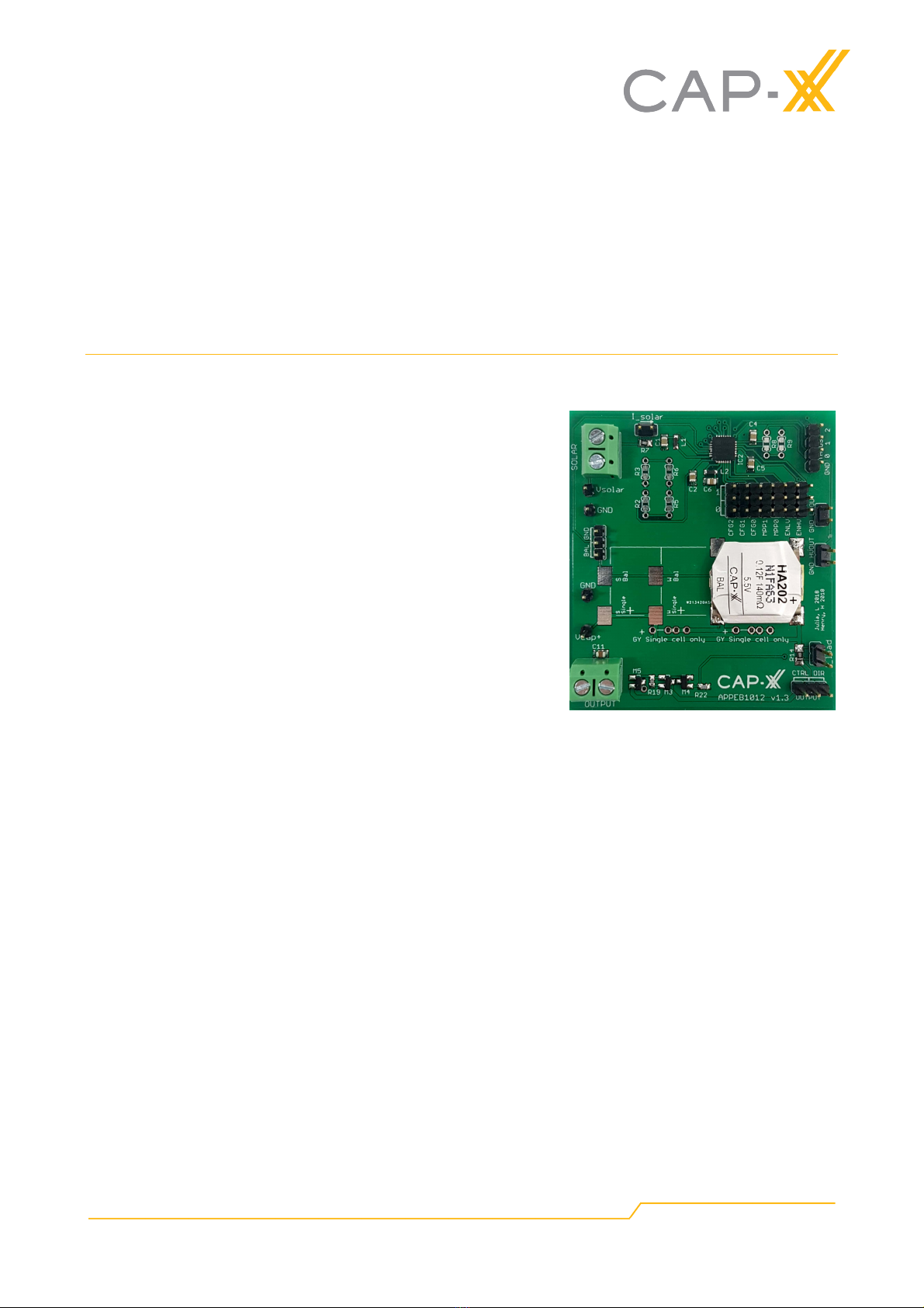
The APPEB1012 is designed to aid the development of energy harvesting applications with a
supercapacitor, particularly solar energy harvesting, using a PMIC to achieve a highly-efficient,
regulated dual-output supply using a supercapacitor as the high power energy storage element.
A cold-start circuit allows the board to start operation with a discharged supercapacitor with an
input voltage as low as 380 mV and input power of just 3 µW. The board incorporates a maximum
power point tracking (MPPT) switch mode power management IC (PMIC), AEM10941 from e-peas.
The IC senses the open-circuit voltage of the solar cell array or other energy harvester every 5
seconds to set the peak power point. For a simpler lower cost alternative that utilises direct
charging from an energy harvester into a supercapacitor please refer to Applications Evaluation
Board, APPEB1011 on our website, www.cap-xx.com .
The AEM10941 has a boost regulator output that charges the supercapacitor. The dual-outputs of
the PMIC are driven by LDO regulators that can be enabled or disabled dynamically by external
control. The low-voltage LDO outputs either 1.2V or 1.8V and the high-voltage output is
configurable between 1.8V and 4.2V. There are configuration headers to determine pre-set charge
for the supercapacitor or external resistors that can be used to set these voltages to other values.
The output of the board can be either directly connected to a load or controlled by the PMIC. The
PMIC enables the output when the supercapacitor is > an upper threshold voltage and disables the
output when the supercapacitor discharges below a lower threshold voltage. The threshold
voltages are defined by the system configuration headers or configuration resistors if the custom
mode is chosen.
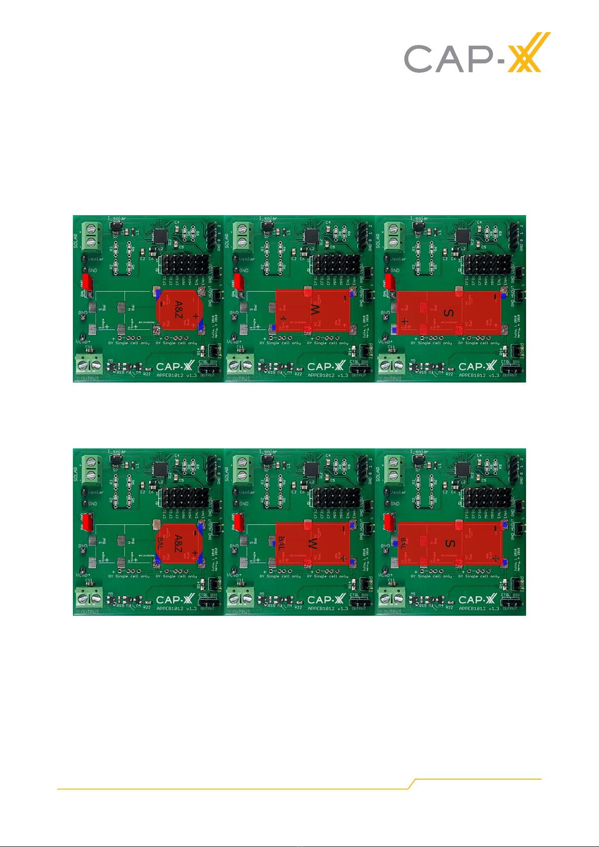
The APPEB1012 also includes an inbuilt active balance control which is a feature of the
AEM10941 so dual cell supercapacitors can be used as well as single cell supercapacitors.
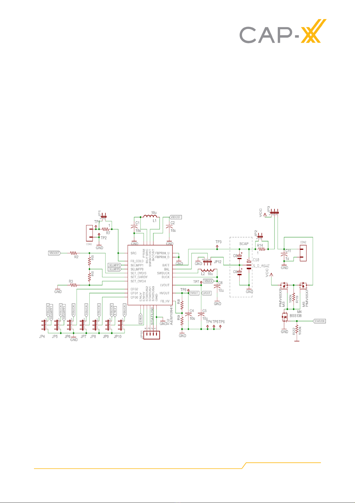
Circuit description
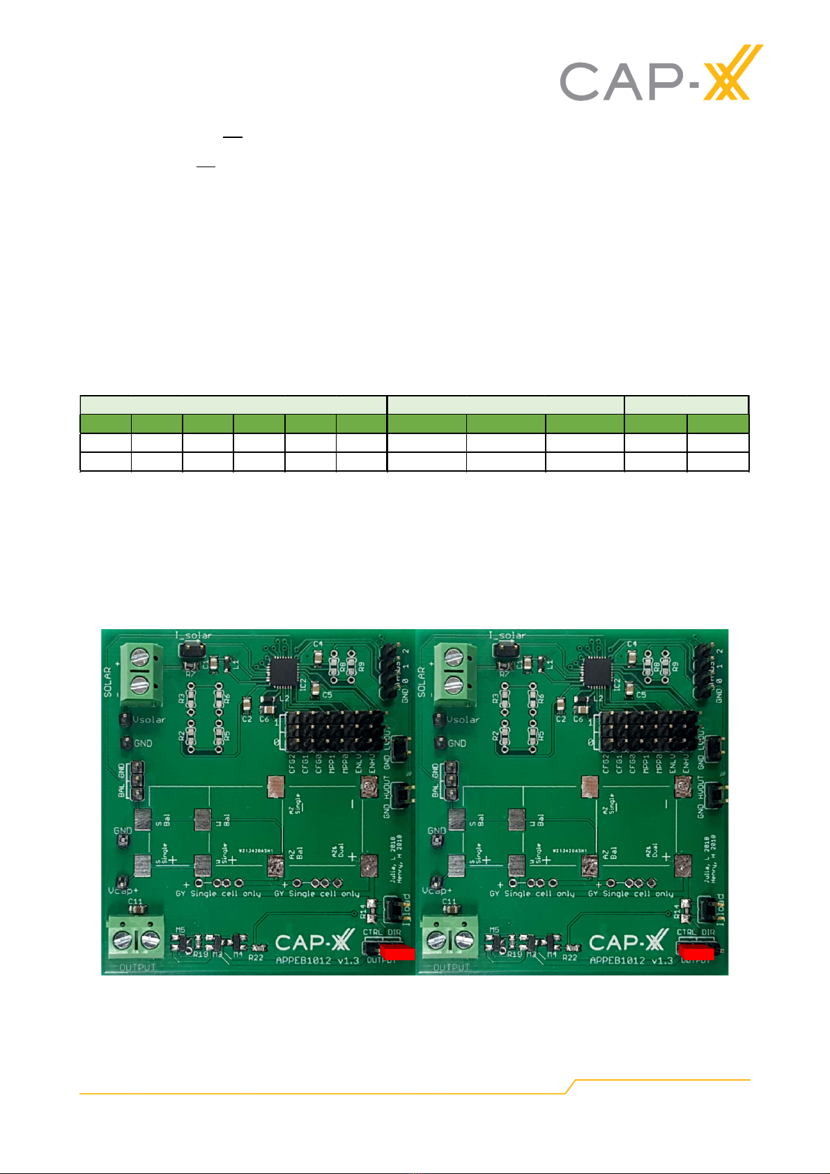
The circuit in figure 1 is separated into two sections. The left half of the schematic contains the
input and the PMIC. The right half is the output control circuit and the output. Where CON1 is the
energy harvester input terminal and CON2 is the output.
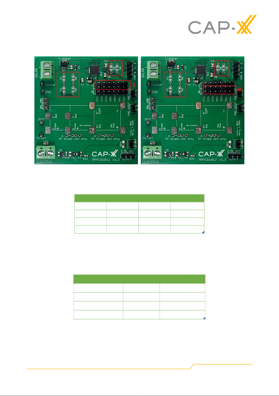
The left half of the circuit consists of the e-peas AEM10941 PMIC. Jumper headers JP4 – JP10
configure the AEM10941, as explained in the section on System Configuration. Resistors R2, R3,
R5 and R6 are optional external resistor pads used for a customising the maximum supercapacitor
voltage. The voltage of the dual LDO outputs can also be found in table 3 and the high voltage
LDO can be externally customised by R8 and R9. The landing pad design for resistors R2, R3, R5,
R6, R8 and R9 can accept either SMD 0603 or 5mm pitch through hole packages.
JP12 is the header that either connects the in-built active balance circuit of the PMIC to ground if a
single cell supercapacitor is used or to the midpoint of a dual cell supercapacitor. If a dual cell
supercapacitor is installed then the active balance circuit must be connected to the mid-point to
ensure the voltage on the top and bottom cells are equal. Please refer to AN1002: Cell Balancing
for information in the importance of balancing dual cell supercapacitors.

User manual for APPEB1012 Revision 1.2, Oct 2019
Solar Energy Harvesting Supercapacitor Evaluation Board using a
PMIC with MPPT
© CAP-XX Pty Limited 2019 | Tel +61 2 9420 0690 | www.cap-xx.com
Page 4of 11
C8, C9 are landing pads for CAP-XX GY cylindrical cells and C10 are the landing pads a CAP-XX
prismatic single cell or dual cell part. R7 is a 1Ωresistor designed to allow the input current to be
measured, while R14 is a 1Ωresistor for measuring the output current. If the voltage drop caused
by 1Ωresistors is too large, they can be replaced with a lower value resistor or shorted via a link
across the jumpers labelled Isolar and Iload. Note these links could be wire loops to enable the use
of a current probe to measure the current.
JP3, labelled OUTPUT selects whether the output is directly connected to the supercapacitor (DIR)
or controlled by the PMIC (CTRL). When the direct output is chosen on JP3 output control PFETs
M3 & M5 are bypassed and M3, M4, and M5 are OFF only drawing ~200nA leakage current. When
the output control is selected, the output is gated by back-back PFETs M3 and M5. The upper and
lower thresholds of the output enable are set in the system configuration such that the PMIC
enables the output when the voltage reaches Vchrdy and disables it approximately 400ms after the
voltage drops below Vovdis. When the supercapacitor voltage is ≥Vchrdy, the PMIC turns M4 on
which in turn switches M3 & M5 ON, connecting the output to the supercapacitor. When the
supercapacitor discharges below Vovdis, the PMIC waits 400ms before turning M4 OFF which
turns OFF M3 & M5, disabling the output and allowing the supercapacitor to charge.
The dual LDO outputs, HVOUT and LVOUT, are also enabled by the charge management
thresholds Vchrdy and Vovdis. This is internally controlled by the PMIC.
Figure 1. Schematic of APPEB1012

User manual for APPEB1012 Revision 1.2, Oct 2019
Solar Energy Harvesting Supercapacitor Evaluation Board using a
PMIC with MPPT
© CAP-XX Pty Limited 2019 | Tel +61 2 9420 0690 | www.cap-xx.com
Page 5of 11
Installation of supercapacitor
CAP-XX prismatic supercapacitor – Single cell
CAP-XX has 4 main package types for the prismatic line. From the smallest to the biggest they are:
Z, A, W and S. The A and Z packages are pin compatible. Pins are reversed between W/S
packages and the A/Z packages. Hence when installing a W or S package single cell, the
supercapacitor must be rotated 180!as shown in figure 2 below. Please ensure that the active-
balance configuration jumper header JP12 is connected to GND as shown in red in the figure
below. This jumper is labelled:
Figure 2: How to correctly install CAP-XX prismatic single cell supercapacitors
CAP-XX prismatic supercapacitor – Dual cell
CAP-XX prismatic dual cells are installed in the same direction. Please ensure that the active-
balance configuration header is connected to the cell midpoint as shown in red in figure 3 below.
Figure 3: How to correctly install CAP-XX prismatic dual cell supercapacitors
CAP-XX cylindrical cells
CAP-XX’s cylindrical products, the GY & HY series (xY), covers capacitance from 1F to 100F in
radial lead form.
The APPEB1012 board only fits single cell radial lead xY products however two single cylindrical
cells can be placed on the board in series to act as a dual cell. This gives access to the midpoint to
the active balance circuit. Our xY line currently has 6 different diameters but with only three
different pin pitches. The PCB through hole design for our cylindrical cells has one positive through
hole and three through holes for the negative pin. When installing an xY series cell, first place the
positive pin into the hole marked +, then slide the negative pin of the cell into one of the negative
through-holes with the correct pitch. Figure 4 below illustrates this.
GND
BAL

User manual for APPEB1012 Revision 1.2, Oct 2019
Solar Energy Harvesting Supercapacitor Evaluation Board using a
PMIC with MPPT
© CAP-XX Pty Limited 2019 | Tel +61 2 9420 0690 | www.cap-xx.com
Page 6of 11
Figure 4: Correctly installing a CAP-XX cylindrical cell supercapacitor
When using only one single CAP-XX cylindrical supercapacitor, the empty cylindrical slot must be
shorted with a wire link from the positive to the negative terminal. Also, the active-balance
configuration header must be connected to GND as shown in red on the left of figure 5.
When 2 CAP-XX cylindrical supercapacitors are connected as dual cells, both supercapacitors
should be fitted with their correct positive and negative terminals and the active-balance
configuration header must be connected to the cell midpoint as shown in red on the right of figure
5.
Figure 5: Illustration to correctly install CAP-XX cylindrical cell device as single cell (left) or dual cell
(right)
System Configuration
There are seven configuration headers on the APPEB1012 used to enable the high-voltage and
low-voltage LDOs, set the MPPT level and to set the charge management thresholds. Selection of

User manual for APPEB1012 Revision 1.2, Oct 2019
Solar Energy Harvesting Supercapacitor Evaluation Board using a
PMIC with MPPT
© CAP-XX Pty Limited 2019 | Tel +61 2 9420 0690 | www.cap-xx.com
Page 7of 11
high or low for the configuration pins are shown in figure 6. Refer to the datasheet of the
AEM10941 if more detail is required.
Figure 6: Configuration headers set all high (left) and all low (right) and configuration resistors
LDO output configurations
Two LDOs are available to supply loads at different operating voltages and can be enabled via the
jumpers on the evaluation board – ENLV and ENHV:
Table 1: Enabling LDO configurations
The LDO outputs, one high and one low voltage, are accessible from the LVOUT and HVOUT
headers with voltages Vlv and Vhv respectively, to supply circuits that require a stable voltage. If
enabled, LVOUT and HVOUT are enabled when the supercapacitor voltage ≥Vchrdy and are
disabled approximately 400ms after the supercapacitor voltage drops below Vovdis.
MPPT Configuration
Table 2: Usage of MPP[1:0]
Two configuration headers, MPP[1:0] allow selection the MPP tracking ratio based on the
characteristic of the input energy harvesting source. The AEM10941 measures the open circuit
voltage of the energy harvester and sets the peak power point voltage to be the % of Voc set in
Table 2.
ENLV ENHV LV&output HV&output
1 1 Enabled Enabled
1 0 Enabled Disabled
0 1 Disabled Enabled
0 0 Disabled Disabled
MPP## [1:0]
Vmpp#/#Voc
0 0 70%
0 1 75%
1 0 85%
1 1 90%

User manual for APPEB1012 Revision 1.2, Oct 2019
Solar Energy Harvesting Supercapacitor Evaluation Board using a
PMIC with MPPT
© CAP-XX Pty Limited 2019 | Tel +61 2 9420 0690 | www.cap-xx.com
Page 8of 11
Charge Management Configuration
Through 3 configuration pins, CFG[2:0], the user can set a particular operating mode from a range
that covers most application requirements without any additional external components.
The three threshold levels are defined as:
•Vovch : OverCharge threshold voltage
•Vchrdy : ChargeReady threshold voltage
•Vovdis : OverDischarge threshold voltage
Table 3: Usage of CFG[1:0]
Custom mode
When CFG [2:0] is set as low, users can use external resistors to customise their required
threshold voltage ranges, as shown in figure 7.
Figure 7: Resistors that set custom mode
All six configuration resistors shown in Figures 6 and 7, must be installed as follows:
Vovch, Vchrdy and, Vovdis are defined by R2, R3, R5 and R6. If we define the total resistor RT as
(R2 + R3 + R5 + R6)
R2, R3, R5 and R6 are calculated as:
•1 M < RT < 100 M
•𝑅2=𝑅𝑇 (1−!!
!!"#$%
)
•𝑅3=𝑅𝑇 (!!
!!"#!
)
•𝑅5=𝑅𝑇 (!!
!!"#!
−!!
!!!!"#
)
•𝑅6=𝑅𝑇 (!!
!!!!"#
−!!
!!"#!
)
Vlv cannot be customised. Vhv, can be customised by R8 and R9. If the total resistor of (R8 + R9)
is RV, R8 and R9 are calculated as:
•1 M < RV < 40 M
Typical(Use
!
CFG![2:0]
!! Vovch Vchrdy Vovdis Vhv Vlv !!!
1 1 1 4.12 3.67 3.60 3.3 1.8 Li-ion(battery
1 1 0 4.12 4.05 3.60 3.3 1.8 Solid(state(battery
1 0 1 4.12 3.67 3.00 2.5 1.8 Li-ion(battery(/(NiMH(battery
1 0 0 2.70 2.30 2.20 1.8 1.2 Single(cell(supercapacitor
0 1 1 4.50 3.67 2.80 2.5 1.8 Dual(cell(supercapacitor
0 1 0 4.50 3.92 3.60 3.3 1.8 Dual(cell(supercapacitor
0 0 1 3.63 3.10 2.80 2.5 1.8 LifePo4(battery
0 0 0 Custom(mode(-(Programmable(through(R2,(R3,(R5,(R6,(R8,(R9 1.8
Configuration(pins
Charge(management(threshold(voltage
LDO(output(voltage

User manual for APPEB1012 Revision 1.2, Oct 2019
Solar Energy Harvesting Supercapacitor Evaluation Board using a
PMIC with MPPT
© CAP-XX Pty Limited 2019 | Tel +61 2 9420 0690 | www.cap-xx.com
Page 9of 11
•𝑅8=𝑅𝑇 (1−!!
!!!
)
•𝑅9=𝑅𝑇 (!!
!!!
)
The resistors should have high values to make the additional power consumption negligible.
Moreover, the following constraints must be adhered to ensure the functionality of the chip:
•Vchrdy + 0.05V < Vovch < 4.5V
•Vovdis + 0.05V < Vchrdy < Vovch - 0.05V
•2.2V < Vovdis
•Vhv < Vovdis - 0.3V
For example, table 4 has two sets of resistor values to customise the charge management
threshold voltages to be different from the PMIC inbuilt options.
Table 4: Example resistor values for typical use
Output mode selection
APPEB1012 has two output modes, either directly connect the output to the supercapacitor or
have the PMIC handle the output based on charge management voltage thresholds This is
accomplished by placing the jumper link on the desired section of the 3-pin header labelled
OUTPUT, illustrated in figure 8 below.
Figure 8: Output mode selection, left image – direct connection, right image – CTRL
controlled
R2 R3 R5 R6 R8 R9 Vovch Vchrdy Vovdis Vhv Vlv
!"# $%&# !%'# ((") *%$# $%'# '%+" '%*+ '%'" !%, !%&
$%&# '%'# $&") !*") +%'# (%,# -%-+ -%!& (%'- '%&* !%&
./012345341627489:
;2<=>93?84>2<1@:A>A42?A
;B8?9:1C8<89:C:<414B?:AB27D1627489:

User manual for APPEB1012 Revision 1.2, Oct 2019
Solar Energy Harvesting Supercapacitor Evaluation Board using a
PMIC with MPPT
© CAP-XX Pty Limited 2019 | Tel +61 2 9420 0690 | www.cap-xx.com
Page 10 of 11
PMIC controlled output voltage
When the PMIC controlled output mode (CTRL) is selected, the voltage range of which output
enables is determined by the charge management configuration. The upper threshold is Vchrdy
which enables the output voltage to the load whilst the output is disabled typically 600ms after the
supercapacitor voltage drops below Vovdis.
Figure 9: Example output voltage operation
In figure 9, HA102 is connected to the APPEB1012 and the supercapacitor voltage and output
voltage was observed. The system configuration was connected as CFG[2:0] = [0 0 0] such that
the PMIC entered custom mode as described in table 3. Custom external resistors were chosen to
create the charge management equal to the first row of table 4.
In this example, Vovch = 2.7; Vchrdy = 2.57V; Vovdis = 2.2V and a constant current of 100mA was
drawn as the load. Furthermore, a power supply limited at 50mA was used as a representation of a
solar cell.
Since the lower threshold of the output voltage is 600ms after the Vscap falls below Vovdis we can
calculate the lower threshold from
𝑖=𝐶
∆𝑣
∆𝑡
Where 𝑖is the load current, 𝐶is the capacitance of the supercapacitor, ∆𝑣is the voltage drop and
∆𝑡is the time taken. Since a HA102 is 0.24F, using the above equation, we can calculate the lower
threshold voltage to be
𝑉
!"#$% =𝑉
!"#$% −
𝑖
𝐶
∆𝑡
=2.2𝑉−
0.1𝐴
0.24𝐹
×0.6𝑠
=1.95𝑉
Hence, the lower and upper output voltage thresholds are at 1.95V and 2.57V as seen in figure 9.
0.00
0.05
0.10
0.15
0.20
0.25
0.30
0
0.5
1
1.5
2
2.5
3
-2.5 2.5 7.5 12.5 17.5 22.5
Current (A)
Voltage (V)
Time (s)
APPEB1012 100mA discharge
Vout
Vscap
Current
MPP
[1:0]
Vmpp / Voc
Output%is%
enabled back%
Output%is%disabled
600ms%after%
Vscap%falls%below%
Vovdis
Boost%mode

User manual for APPEB1012 Revision 1.2, Oct 2019
Solar Energy Harvesting Supercapacitor Evaluation Board using a
PMIC with MPPT
© CAP-XX Pty Limited 2019 | Tel +61 2 9420 0690 | www.cap-xx.com
Page 11 of 11
Status Pins
Users are also given access to the STATUS[2:0] logic output levels on the status pins if required.
The status pin STATUS[0] turns high when the supercapacitor voltage reaches Vchrdy to signal
that the LDOs are operational and can be enabled.
If the supercapacitor voltage gets discharged below Vovdis, the LDOs are gated OFF and the
boost converter on the AEM10941 is no longer supplied by the storage element to protect it from
further discharge. When Vscap drops below Vovdis STATUS[1] changes from low to high, to warn
that the system will soon shut down, and ~600ms later, when shutdown occurs, STATUS[1] and
STATUS[0] both go from high to low. This is illustrated in figure 10.
Figure 10: Example STATUS pin operation
The status of the MPP controller is reported with one dedicated status pin (STATUS[2]). The
status pin is asserted when the input is set open circuit to measure VOC of the energy harvester.
Further Information
CAP-XX will be pleased to provide further information on the applications described here, and on
the use of supercapacitors in any application. Please use the contact details provided on the CAP-
XX web site (www.cap-xx.com).
This user manual is available on the CAP-XX web site. On the web site you may also find product
bulletins, datasheets, SPICE models, application white paper, application briefs and design-aid
calculator (http://cap-xx.com/resources/resources.htm).
Table of contents