CAPIC - QUIMPER France
Tél. : +33 2 98 64 77 00
Fax : +33 2 98 52 06 47
Email : capic
capic-fr.com
NOTICE N° 2901.1219
Page 5
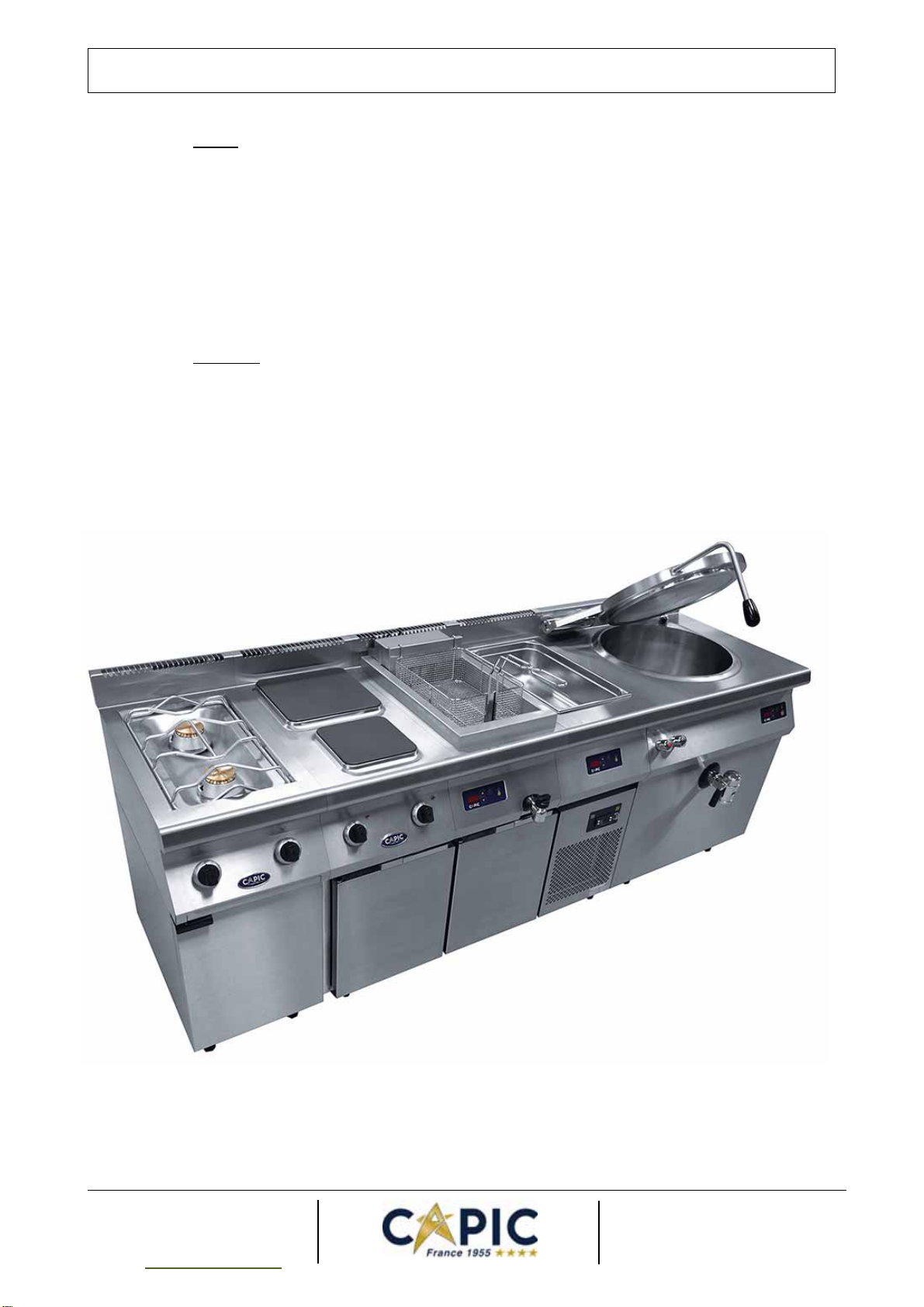
USER MANUAL
1 - INSTALLATION
1.1 Regulation:
It is essential to become acquainted with the security administration of each state or country.
The equipment must be installed in accordance to the regulations and norms in force by a
qualified installer and in a well-ventilated area. Depending on the type of establishment and the
kitchen design, wiring or gas installation and ventilation are subject to very specific safety standards,
which vary from one region to another.
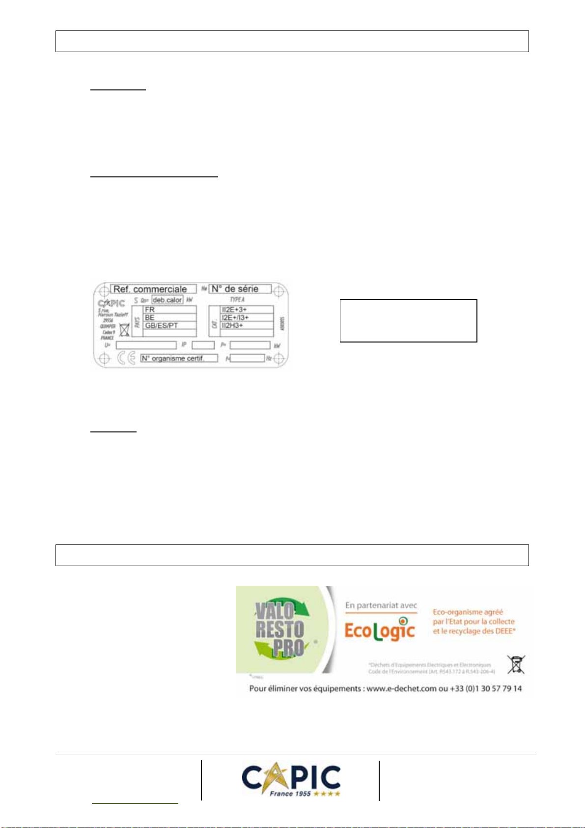
Any adaptation to another gas must be performed by a qualified installer and meet the
regulations and standards of the country.
The equipment must be installed in a well-ventilated area to avoid the
creation of harmful substances for the health in the area in which the
appliance is placed.
The clean air output required for the combustion is 2m3/h per kW of heat release rate.
1.2 Cleaning before use:
Before the first ignition of the device, the piece of equipment must be impeccably washed.
The body of each piece of equipment is protected by a film which guarantees its good
condition. To remove this film, cut it at an angle, pull and peel it off on the entire surface. If necessary,
remove the possible remaining glue with a solvent.
After production and tests, the cast-iron hotplates are coated with oil to prevent them from
corrosion. Degrease them with a domestic detergent. Rinse and dry them carefully before making
them ready for use by melting fat on the top.
1.3 General implantation:
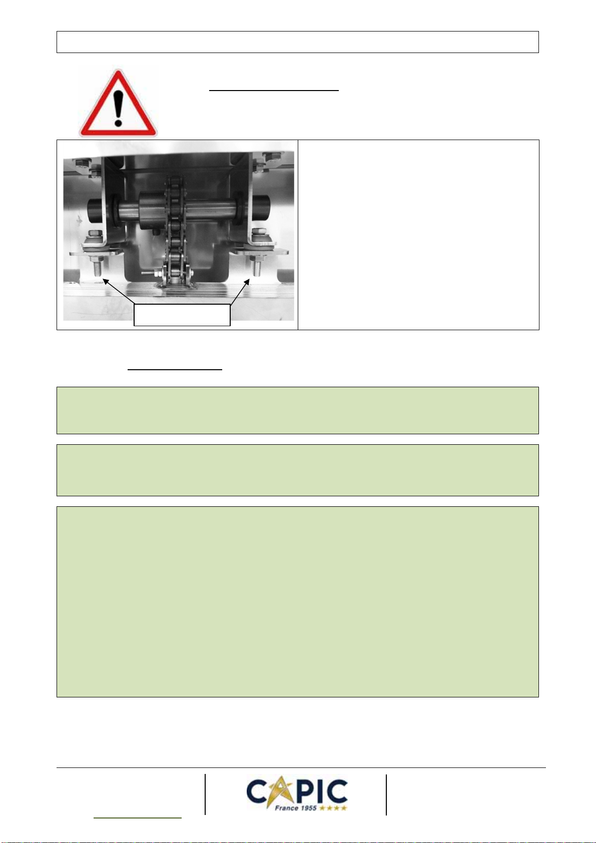
The unit must be stable and placed on a perfectly horizontal area. They are mounted on
height adjustable feet assembled by screwing or unscrewing a nozzle. Use a 36 mm wrench to adjust
the feet.
The service area of the unit must be free and well lighted to facilitate the access to the control
panel and to the working area.
The area must be well ventilated with a high quality extraction system for the waste gas and
steam. For wall-mounted equipment, the back wall of the premises must be built in incombustible
material.
For the wheeled units (in option):
-Plan automatically a safe fastener and also a safety cable to maintain the unit fixed, stable and at
level. Always use the breaks of the wheels to avoid possible risks during the utilization and possible
brutal pulling of the gas piping, electric circuits and water network.
-Plan a completely free service area.
-Do not move the unit when it is ignited. The hot oil, hot surfaces and containers falls could cause
serious burns.
- Before moving the machine, wait until a complete cooling, remove all containers and carry out a
drain of the tank if necessary.