manuals.online logo
Brands
  1. Home
  2. •
  3. Brands
  4. •
  5. Caple
  6. •
  7. Garbage Disposal
  8. •
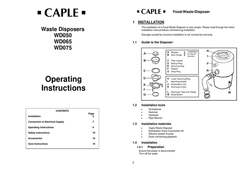
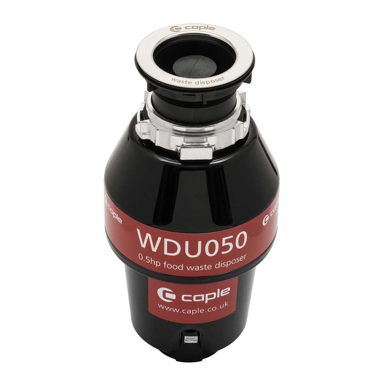
  9. Caple WDU050 User manual

Caple WDU050 User manual

Other manuals for WDU050

2

This manual suits for next models

2

Other Caple Garbage Disposal manuals

Caple WDU125 User manual

Caple

Caple WDU125 User manual

Caple WD050 User manual

Caple

Caple WD050 User manual

Caple WDU050 User manual

Caple

Caple WDU050 User manual

Caple WDU050 User manual

Caple

Caple WDU050 User manual

Caple WDU060 User manual

Caple

Caple WDU060 User manual

Popular Garbage Disposal manuals by other brands

Franke CE-50 User and installation manual

Franke

Franke CE-50 User and installation manual

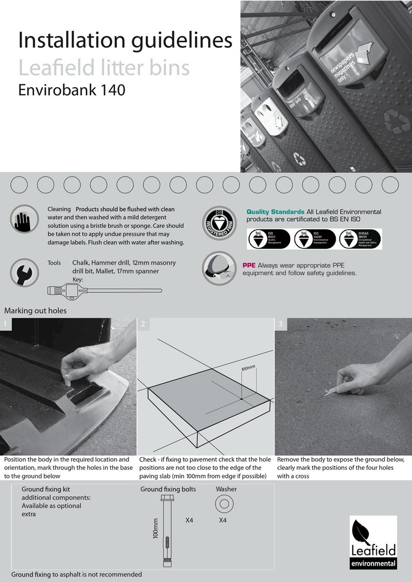
Leafield Environmental Envirobank 140 Installation guidelines

Leafield Environmental

Leafield Environmental Envirobank 140 Installation guidelines

Insinger I-6 brochure

Insinger

Insinger I-6 brochure

KitchenAid KCDB250G2 parts list

KitchenAid

KitchenAid KCDB250G2 parts list

Scheppach HP3000S Translation from the original instruction manual

Scheppach

Scheppach HP3000S Translation from the original instruction manual

Zanussi DU 4400 Instruction booklet

Zanussi

Zanussi DU 4400 Instruction booklet

MULTIQUIP Mikasa series MVH-306D Operation and parts manual

MULTIQUIP

MULTIQUIP Mikasa series MVH-306D Operation and parts manual

Max Maxmatic 4000c operating instructions

Max

Max Maxmatic 4000c operating instructions

KitchenAid KCDB250S0 parts list

KitchenAid

KitchenAid KCDB250S0 parts list

Belle PCX 20/50 Operator's manual

Belle

Belle PCX 20/50 Operator's manual

InSinkErator Model LC-50 installation manual

InSinkErator

InSinkErator Model LC-50 installation manual

Rubbermaid Infinity 9W31 manual

Rubbermaid

Rubbermaid Infinity 9W31 manual

Westinghouse 3/4 HP owner's manual

Westinghouse

Westinghouse 3/4 HP owner's manual

Haigh Quattro Vanguard Original manual

Haigh

Haigh Quattro Vanguard Original manual

Central Machinery 70167 Owner's manual & safety instructions

Central Machinery

Central Machinery 70167 Owner's manual & safety instructions

Teral DSP-125H-AWV Quick start manual

Teral

Teral DSP-125H-AWV Quick start manual

Mistral Ultra 10504 Specifications

Mistral

Mistral Ultra 10504 Specifications

Atlas Copco HC 150 Safety and operating instructions

Atlas Copco

Atlas Copco HC 150 Safety and operating instructions

manuals.online logo
manuals.online logoBrands
  • About & Mission
  • Contact us
  • Privacy Policy
  • Terms and Conditions

Copyright 2025 Manuals.Online. All Rights Reserved.

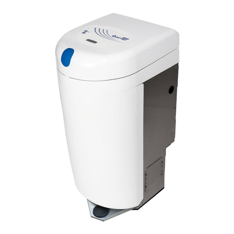
Waste Disposal Unit
Instruction Manual
WDU050, WDU075
& WDU100
Contact Caple on 0117 938 7420 for spare parts or www.caple.co.uk
Instruction manual WDU050, WDU075 & WDU100 Instruction manual WDU050, WDU075 & WDU1002 3
Please keep this instruction manual for future reference Please keep this instruction manual for future reference
INSTRUCTIONS
Read these instructions carefully and completely before
using your Waste Disposal Unit, keep it in a convenient
place for reference when necessary.
NOTE: This Waste Disposal Unit has been designed to
operate at 220/240V~, 50/60 Hz household current
exclusively. Using any other voltage or Hz adversely affects
performance, and invalidates the warranty.
CAUTION: Be sure to review the Safety Instructions
Warning and Electrical Connection section before using
disposer.
NOTE:
Model information and serial number appears on the
rating label affixed to bottom of the disposer. For your
convenience, write down the model and serial numbers
prior to installation.
CONTENTS
Safety Information 4
Electrical Connection 7
Installation Instructions 11
Dimensions 17
Operating Instructions 18
Troubleshooting 20
Service Information 23
Caple Contact Details 24
Instruction manual WDU050, WDU075 & WDU100 Instruction manual WDU050, WDU075 & WDU1004 5
Please keep this instruction manual for future reference Please keep this instruction manual for future reference
SAFETY INSTRUCTIONS
Instructions pertaining to a risk of fire, electric shock or
injury to persons. Save these instructions.
WARNING:
-Use this appliance only for it intended purpose, as
described in this instruction manual. Read all instruction
before using the waste disposal unit.
-To reduce the risk of injury, close supervision is required
when an appliance is in use near children.
-DO NOT put your fingers or hands into the waste
disposer.
-If the appliance becomes jammed or a object is stuck,
turn off the power at the mains before attempting to
remove it.
-When attempting to loosen a jam, use a long wooden
object such as a wooden spoon.
-When attempting to remove objects from a waste
disposer, use non-magnetic long handled tongs instead
of pliers.
-To reduce the risk of materials being expelled when in
use and causing harm, do not put the following in the
disposer:
1. Clam or oyster shells.
2. Caustic drain cleaners or similar.
3. Glass, china or plastic.
4. Large whole bones.
5. Metal such as bottle caps, tin cans, utensils or
aluminum foil.
6. Hot grease or other hot liquids.
7. Whole corn husks.
-This appliance must be installed in accordance to local
laws and standards. We recommend using a qualified
installer.
-Do not disassemble the appliance for any reason, there
are no serviceable parts.
-When not using the disposer we recommend leaving the
stopper in place to help prevent items falling in.
-The appliance must be installed ensuring the reset
button is readily accessible.
-This appliance is not intended for use by persons
(including children) with reduced physical, sensory or
mental capabilities or lack of experience and knowledge,
unless they have been given supervision or instruction
concerning the use of the appliance by a person
responsible for their safety.
-Children should be supervised to ensure they do not play
with the appliance.
-If the supply cord becomes damaged, it must be replaced
by a Caple engineer or a similary qualified person in
order to avoid a hazard.
-Make sure the installation of this appliance is
allowed by the local authorities.
-This marking indicated that this product should
not be disposed of with other household waste.
Instruction manual WDU050, WDU075 & WDU100 Instruction manual WDU050, WDU075 & WDU1006 7
Please keep this instruction manual for future reference Please keep this instruction manual for future reference
To prevent possible harm to the environment or human
health from uncontrolled waste disposal, recycle
it responsibly to promote the sustainable reuse of
materials. For more detailed information about treatment,
recovery and recycling of this product, please contact
your local council, your household waste disposal service
or the retailer where you purchased the product.
-For correct earthing instructions please see the ‘Electrical
connection’ section of this manual.
-Never use this appliance in a damp location (for example
a bathroom or laundry room)
-No not use this appliance to dispose of hard materials
such as glass or metal.
-Switch off or unplug the appliance before attempting to
free a jammed rotor.
ELECTRICAL CONNECTION
If you are not familiar with electrical installations and procedures, please contact a qualified
electrician.
DANGER
An incorrect earth connection can result in a risk of electric shock. Check with a qualified
electrician if you are in doubt as to whether the waste disposal unit is correctly earthed. Do
not modify the plug provided with the appliance, if it will not fit in the socket have a correct
connection installed by a qualified electrician.
These appliances are meant for household use, do not use in a commercial application.
EARTHING INSTRUCTIONS
This appliance must be earthed. In the event of a malfunction or breakdown earthing provides a
path of least resistance for the electric current to reduce the risk of electric shock. This appliance
is equipped with a cord having an equipment earthing conductor and earthed plug. The plug must
be plugged into an appropriate socket that is correctly installed and earthed in accordance with
the local codes and ordinances.
If you are not familiar with electrical power and procedures, call a qualified electrician.
The power cord and/or connections must comply with local codes and ordinances.
FOR MODELS NOT EQUIPPED WITH A CORD:
»Choose a power cord not less than H 05V V-F, 3G1.0mm incorporate with a plug rated 250V
13A (fuse in plug:250V,10A) approved by BSI with matched ground wire for the UK market
(Standard: BS1363-1) or a plug rated 250V 16A approved by VDE with matched ground wire
(Standard: DINVDE0620-1).
»Chose a power cord not less than H05VV-F, 3G1.0mm and fitted with a switch, the switch
shall be directly connected to the supply terminals and shall have a contact separation
in all poles, providing full disconnect under overvoltage category III conditions (the full
disconnection not less than 3mm).
»Make sure the switch is easily visible and accessible. The recommend distance between this
appliance and electrical switch is within 2m.
Instruction manual WDU050, WDU075 & WDU100 Instruction manual WDU050, WDU075 & WDU1008 9
Please keep this instruction manual for future reference Please keep this instruction manual for future reference
DANGER:
Improper connection of the equipment-grounding conductor can result in a risk of electric shock.
Check with a qualified electrician if you are in doubt as to whether the appliance is properly
grounded.
NOTE:
Disconnect the electric power to disposer circuit before installation. Turn the circuit breaker to the
OFF position or remove the fuse.
A. Connect the disposer to220-240 Volt, 50-60 HzAC current only.
B. If a plug-in cord is used, use a three-prong plug. A earth wire should
be attached to the ground screw in the bottom of the disposer (end
bell).
Follow the lead connected to this blade marked with a ‘L’ and attach
that lead to the blue wire on the waste disposer.
C. Use a cable clamp strain relief connector where the power cord enters
the disposer.
NOTE:
When viewing face of electrical plug with the earth pin
at top, the left blade is connected to the identified wire.
3
IIMMPPOORRTTAANNTTSSAAFFEETTYYIINNSSTTRRUUCCTTIIOONNSS..
READ ALL INSTRUCTIONS BEFORE USING.
WARNING!
Electrical connection (cont.)
If yo u are not familiar with electrical po wer and procedures, callaqualifie d electrician.
1. Choose a power cord notless than H05V V-F,
2. Chose a power cord notless than H 05VV-F,
3G1.0mm and fitted withaswitch,the switch
shall be dire ctly connected to the supply
term inals and shall have a contact separation in
all p oles, pr oviding full disconnect under
overvol tage category III conditions(the full
disc onn ection not less than 3mm).
3. Make sure the switch is easily visible
EEAARRTTHHIINNGG IINNSSTTRRUUCCTTIIOONNSS::
This appliance must be earthed. In the event of a
malfunction or breakdown earthing provides a
path of least resistance for the electric current to
reduce the risk of electric shock. This appliance is
equipped with a cord having a equipment earthing
conductor and earthed plug. The plug must be
plugged into a appropriate socket this is correctly
installed and earthed in accordance with the local
codes and ordinances.
DDAANNGGEERR::
Im proper connection of the equipment-grounding
conductor can result ina risk
of electric shock. Check with a qualified
electrician if y ou are in doubt as to whether the
appliance is properly grounded.
NNOOTTEE::
Disconnect the electric power to disposer circuit
before i nstallation. Turn the circuit breaker to the
OOFFFF position or remove the fuse.
A. Connect the disposer to 220-240 Volt, 50-60
Hz AC c urrent only.
B. If a plug-in cord is used, use a three-prong
plug. A earthwire should be attached to the
ground screw in the bottom of the disposer (end
bell).
2
3G1.0mm incor porate with a plug rated 250V
13A (fuse in plug: 250V, 10A) approved by BSI
with matchedground w ire forthe UK market
(Sta nda rd: BS1363-1) or a plug rated 250V 16A
approve d by VDE with matched ground wire
(Sta nda rd: DIN VDE 062 0-1).
The power cord and/or connections must
comply with local codesand ordinances.
FFoorr
MMooddeellssNNoott
EEqquuiippppeeddwwiitthhaa
CCoorrdd::
and accessible. The recommend distance
between this applianceand
electrical switch is
within 2m.
TTooaattttaacchhaa
ppoowweerrccoorrdd::
2
To wire your disposer directly into the mains:
GROUNDING INSTRUCTIONS:
This appliance must be connected to a grounded, metal,
permanent wiringsystem, or an equipmentgrounding
conductor must be run with the circuit conductors and
connected to the equipmentgrounding terminal or lead
on the appliance.
A. If you use BX cable:
1. These products are designedforhousehold use.
2. Connect a line wire to blue lead of disposer with a wire
nut. Connecttheneutral wire to thebrown lead of
disposer witha wire nut. Connect the bare ground wire
to the ground screw. The ground wire should be clamped
and held by a strain relief bracket.
3. Do not usearigid conduit for the wiring connection.
4. A dedicated acceptable motor switch,with the off
position marked,shall be provided for this disposerat the
time of installation (not included). The switch shall be
mounted in sight of the disposer or the
sinkopening forthe disposer.
If BX cable is notused, provideaseparate ground wire
to thenearest reliable ground, using the screw in the
end bell for the ground wire.
Follow the lead connected to this b lade marked with
a 'L' and attachthat lead t o the blue wire on the
waste disposer.
NNOOTTEE:: When viewing
face of electrical plug
with the earth pin
at top, the left blade
is connected to the
identified wire.
Strain Relief bracket
C. Us e a cable clam p strain
re lief connector where the
power cord en ters the
dispo ser.
Nut
Red reset button
Ground screw
Wire nut
Remove
bottom cap
To house cur rent
or the power cord
Bottom of the
disposer (end bell)
3
IIMMPPOORRTTAANNTTSSAAFFEETTYYIINNSSTTRRUUCCTTIIOONNSS..
READ ALL INSTRUCTIONS BEFORE USING.
WARNING!
Electrical connection (cont.)
If yo u are not familiar with electrical power and procedu res, callaqualifie d electrician.
1. Choose a power cord notless than H05V V-F,
2. Chose a power cord notless than H05V V-F,
3G1.0mm a nd fitted withaswitch,the switch
shall be dire ctly connected to the supply
terminals and shall have a contact separation in
all poles, pr oviding full disconnect under
overvoltage category III conditions(t he full
disconn ecti on not less than 3mm).
3. Make sure the switch is easily visible
EEAARRTTHHIINNGG IINNSSTTRRUUCCTTIIOONNSS::
This appliance must be earthed. In the event of a
malfunction or breakdown earthing provides a
path of least resistance for the electric current to
reduce the risk of electric shock. This appliance is
equipped with a cord having a equipment earthing
conductor and earthed plug. The plug must be
plugged into a appropriate socket this is correctly
installed and earthed in accordance with the local
codes and ordinances.
DDAANNGGEERR::
Im proper c onnection of the equipment-grounding
conductor can result ina risk
of electric shock. Check with a qualified
electrician if you are in doubt as to whether the
appliance is properly grounded.
NNOOTTEE::
Disconnect the electric power to disposer circuit
before installation. Turn the circuit breaker to the
OOFFFF position or remove the fuse.
A. Connect the disposer to 220-240 Volt, 50-60
Hz AC c urrent only.
B. If a plug-in cord is used, use a three-prong
plug. A earthwire should be attached to the
ground screw in the bottom of the disposer (end
bell).
2
3G1.0mm i ncorporate with a plug rated 250V
13A (fuse in plug: 250V, 10A) approved by BSI
with matchedground w ire forthe UK market
(Standa rd: BS1363-1) or a plug rated 250V 16A
approved by VDE with match ed ground wire
(Standa rd: DIN VDE 0620-1).
The power cord and/or connections m ust
comply with l ocal codesand ordinances.
FFoorr
MMooddeellssNNoott
EEqquuiippppeeddwwiitthhaa
CCoorrdd::
and accessible. The reco mmend distance
between this applianceand
electrical switch is
within 2m.
TTooaattttaacchhaa
ppoowweerrccoorrdd::
2
To wire your disposer directly into the mains:
GROUNDING INSTRUCTIONS:
This appliance must be connected to a grounded, metal,
permanent wiringsystem, or an equipmentgrounding
conductor must be run with the circuit conductors and
connected to the equipmentgrounding terminal or lead
on the appliance.
A. If you use BX cable:
1. These products are designedforhousehold use.
2. Connect a line wire to blue lead of disposer with a wire
nut. Connecttheneutral wire to thebrown lead of
disposer witha wire nut. Connect the bare ground wire
to the ground screw. The ground wire should be clamped
and held by a strain relief bracket.
3. Do not usearigid conduit for the wiring connection.
4. A dedicated acceptable motor switch,with the off
position marked,shall be provided for this disposerat the
time of installation (not included). The switch shall be
mounted in sight of the disposer or the
sinkopening forthe disposer.
If BX cable is notused, provideaseparate ground wire
to thenearest reliable ground, using the screw in the
end bell for the ground wire.
Follow the lead connected to this blade marked with
a 'L' and attachthat lead t o the blue wire on the
waste disposer.
NNOOTTEE:: When viewing
face of electrical plug
with the earth pin
at top, the left blade
is connected to the
identified wire.
Strain Relief bracket
C. Use a cable clam p strain
relief connector where the
powe r cord en ters the
dispo ser.
Nut
Red reset b utton
Ground screw
Wire nut
Remove
bottom cap
To house current
or the po wer cord
Bottom of the
disposer (e nd b ell)
3
IIMMPPOORRTTAANNTTSSAAFFEETTYYIINNSSTTRRUUCCTTIIOONNSS..
READ ALL INSTRUCTIONS BEFORE USING.
WARNING!
Electrical connection (cont.)
If you are not familiar with electrical power and procedures, callaqualifie d electrician.
1. Choose a power cord notless than H 05VV-F,
2. Chose a power cord notless than H05VV-F,
3G1 .0mm a nd fitted withaswitch,the switch
shall be dire ctly connected to the supply
terminals and shall have a contact separation in
all poles, providing full disconnect under
overvol tage category III conditions(t he full
disconnection not less than 3mm).
3. Make sure the switch is easily visible
EEAARRTTHHIINNGG IINNSSTTRRUUCCTTIIOONNSS::
This appliance must be earthed. In the event of a
malfunction or breakdown earthing provides a
path of least resistance for the electric current to
reduce the risk of electric shock. This appliance is
equipped with a cord having a equipment earthing
conductor and earthed plug. The plug must be
plugged into a appropriate socket this is correctly
installed and earthed in accordance with the local
codes and ordinances.
DDAANNGGEERR::
Improper c onnection o f the equipment-grounding
conductor can result ina risk
of electric shock. Check with a qualified
electrician if you a re in doubt as to whether the
appliance is properly grounded.
NNOOTTEE::
Disconnect the electric power to disposer circuit
before i nstallation. Turn the circu it breaker to the
OOFFFF position or remove the fuse.
A. C onnect the disposer to 220-240 Volt, 50-60
Hz AC c urrent only.
B. I f a plug-in cord is used, use a three-prong
plug. A earthwire should be attached to the
ground screw in the bottom of the disposer (end
bell).
2
3G1 .0mm i ncorporate w ith a plug rated 250V
13A (fuse in plug: 250V, 10A) approved by BSI
with matchedground w ire forthe UK market
(Standa rd: BS1363-1) or a plug rated 250V 16A
app roved by VDE with matched ground wire
(Standa rd: DIN VDE 0620-1).
The power cord and/or connections must
comply with local codesand ordinances.
FFoorr
MMooddeellssNNoott
EEqquuiippppeeddwwiitthhaa
CCoorrdd::
and accessible. The recommend distance
between this applianceand
electrical switch is
within 2m.
TTooaattttaacchhaa
ppoowweerrccoorrdd::
2
To wire your disposer directly into the mains:
GROUNDING INSTRUCTIONS:
This appliance must be connected to a grounded, metal,
permanent wiringsystem, or an equipmentgrounding
conductor must be run with the circuit conductors and
connected to the equipmentgrounding terminal or lead
on the appliance.
A. If you use BX cable:
1. These products are designedforhousehold use.
2. Connect a line wire to blue lead of disposer with a wire
nut. Connecttheneutral wire to thebrown lead of
disposer witha wire nut. Connect the bare ground wire
to the ground screw. The ground wire should be clamped
and held by a strain relief bracket.
3. Do not usearigid conduit for the wiring connection.
4. A dedicated acceptable motor switch,with the off
position marked,shall be provided for this disposerat the
time of installation (not included). The switch shall be
mounted in sight of the disposer or the
sinkopening forthe disposer.
If BX cable is notused, provideaseparate ground wire
to thenearest reliable ground, using the screw in the
end bell for the ground wire.
Follow the lead connected to this blade marked with
a 'L' and attachthat le ad t o the blue wire on the
waste disposer.
NNOOTTEE:: When viewing
face of electrical plug
with the earth pin
at top, the left blade
is connected to the
identified wire.
Strain Relief bracket
C. Use a cable clamp strain
re lief connector where the
powe r cord en ters the
disposer.
Nut
Red reset b utton
Ground screw
Wire nut
Remove
bottom cap
To house current
or the po wer cord
Bottom of the
disposer (end b ell)
TO WIRE YOUR DISPOSER DIRECTLY INTO THE MAINS
GROUNDING INSTRUCTIONS
This appliance must be connected to a grounded, metal, permanent wiring system, or an
equipment grounding conductor must be run with the circuit conductors and connected to the
equipment grounding terminal or lead on the appliance.
IF YOU USE BX CABLE:
1. These products are designed for household use.
2. Connect a line wire to blue lead of disposer with a wire nut. Connect the neutral wire to the
brown lead of disposer with a wire nut. Connect the bare ground wire to the ground screw.
The ground wire should be clamped and held by a strain relief bracket.
3. Do not use a rigid conduit for the wiring connection.
4. A dedicated acceptable motor switch, with the off position marked,shall be provided for this
disposer at the time of installation (not included). The switch shall be mounted in sight of the
disposer or the sink opening for the disposer.
5. If BX cable is not used, provide a separate ground wire to the nearest reliable ground, using
the screw in the end bell for the ground wire.
Instruction manual WDU050, WDU075 & WDU100 Instruction manual WDU050, WDU075 & WDU10010 11
Please keep this instruction manual for future reference Please keep this instruction manual for future reference
INSTALLATION INSTRUCTIONS
Before you begin read these instructions completely and carefully.
IMPORTANT
Keep these instructions
IMPORTANT
Observe all governing codes and ordinances.
NOTE TO INSTALLER
Be sure to leave these instructions with the consumer.
NOTE TO CONSUMER
Keep these instructions for future reference.
SKILL LEVEL
The installation of this appliance requires basic mechanical skills.
COMPLETION TIME
1 hour.
NOTE
The correct installation is the responsibility of the installer.
PREPARATION
1. Disconnect electrical power supply to the disposer.
2. Remove the old disposer or sink flange assembly.
3. Inspect drain line. If it is heavily coated with hardened grease and accumulations, clean out
before you proceed with the installation.
4. Remover old sealing materials and gasketing from the sink opening, both top and bottom.
NOTE
The top and bottom of the sink surfaces must be free of any materials to prevent leaks.
IIMMPPOORRTTAANNTTSSAAFFEETTYYIINNSSTTRRUUCCTTIIOONNSS..
READ ALL INSTRUCTIONS BEFORE USING.
WARNING!
Electrical connection(cont.)
If yo u are not familiar with elec trical power and procedures, c ontact a qualified electrician.
Below are some typical electrical connections:
Wall outlet
Air switch
Air switch Bu tton
Control s witch
Wall outlet Disposer Disposer
4
INSTALLATION TWO: Alternately if you do not have a wall switch or
if you prefer, we also have a air switch available (product code
WDUAIR). This is available directly from Caple or the retailer you
purchased our appliance. This can be installed in the worksurface or
sink (see below).
INSTALLATION ONE: You can install this waste disposal unit
with a wall mounted control switch (not supplied) as shown
below.
TYPICAL ELECTRICAL CONNECTIONS
INSTALLATION ONE
You can install this waste disposal unit with a wall
mounted control switch (not supplied).
INSTALLATION TWO:
Alternately if you do not have a wall switch or if you
prefer, we also have a air switch available (product
code WDUAIR). This is available directly from Caple or
the retailer you purchased our appliance. This can be
installed in the worksurface or sink (see below).
Instruction manual WDU050, WDU075 & WDU100 Instruction manual WDU050, WDU075 & WDU10012 13
Please keep this instruction manual for future reference Please keep this instruction manual for future reference
WHAT YOU WILL NEED
»Steel punch or wooden dowel
»Petroleum jelly or liquid soap
»Hose clamp
»Dishwasher drain connector
»Adjustale pipe wrench
»Plumbers putty (for ceramic s inks)
»Stepped rubber drain adapter
»Wire nuts
»Cable connector
»Flexible drain pipe
»Power cord kit
COMPONENTS AND INSTALLATION
NOTE
Pay close attention to the order of the sink
flange parts, as they have been
correctly assembled by the factory.
A. Disassemble the sink flange assembly from
the disposer by turning the mount ring to
the left (clockwise) and removing it.
B. Raise the mount ring toward the top of the
sink flange. Remove the cushion mount and
the mount ring.
You may want to practice installing the
cushion mount at this point before you are
under the sink.
C. Unscrew the support ring from the sink
flange and remove the fiber gasket. You are
now left with the sink flange and the rubber
gasket.
D. The rubber gasket is used instead of
plumbers putty with stainless steel sinks.
Some ceramic sinks will require putty or
silicone.
E. If no putty is used, insert the sink flange
through the rubber gasket into the sink
opening. Do not turn the flange once it is
seated.
F. If you use putty instead of the gasket,
form a ring around the underside of the
sink flange. Insert the flange into the sink
opening, press down hard to squeeze out
excess putty. From under the sink, trim off
excess putty flush with the bottom edge of
the sink opening.
IInnssttaallllaattiioonn IInnssttrruuccttiioonnssFood waste disposer
BBeeffoorree yyoouu bbeeggiinn
RReeaaddtthheesseeiinnssttrruuccttiioonnssccoommpplleetteellyyaannddccaarreeffuullllyy
CCoommpplleettiioonnTTiimmee--
IIMMPPOORRTTAANNTT--Keep these instructions
IIMMPPOORRTTAANNTT--Observe all governingcodes
and ordinances.
NNootteettooIInnssttaalllleerr-- B e sure to lea ve these
instructions with the C onsumer.
NNootteettooCCoonnssuummeerr--Kee p these instru ctions for
future re ference.
SSkkiillllLLeevveell--The installation of this a pplian ce requires
basic me chanical skills.
Phil lips and flat blade sc rewdrivers
Cha nnel lo ck plie rs , slip joint Hammer
Nut driver
PPrreeppaarraattiioonn
1. Disc onnec t electrical p ower supply to the disp oser.
2. Rem ove the old disp oser or sink flange assembly.
3. Insp ect drain line. If it is heav ily coa ted with hardened
grease and a ccumu lations,clean out before you
proceed with the installation.
4. Rem over o ld sealing m aterials and gasketing from
the sink opening, both top an d bottom.
NOTE: The top and bot tom of the sink surface s must be
fre e of any ma terials to prevent leaks.
AAddddiittiioonnaall mmaatteerriiaallss yyoouu mmaayy nneeeedd
1. St eel pu nch or woode n dowel
2. Pe troleum jelly or liqu id soap
3. Ho se clamp
4. Di shwas her draincon nector
5. Adjustable pipe wrench
6. Pl umbers putty (for ceramic sinks)
7. St epped rubber drain adapter
8. W ire nuts
9. Ca ble co nnector
10. F lexible drain pipe
11. Power cord kit
5
WWhhaatt yyoouu wwiillll nneeeedd
TThhee ccoorrrreecctt iinnssttaallllaattiioonn iiss tthhee rreessppoonnssiibbiilliittyy ooff tthhee iinnssttaalllleerr..
1 hour
6
NNOOTTEE:: Pay close attention to the order o f the sin k flange
parts, as they have been correct ly assembled by the
factory.
A. Disa ssemble the sink flange assembly from the
disposer by turning the mount ring to the left (clockwise)
and removing it.
B. Raise the mount ring toward the top of the sink flange.
Remove the cushion mount and the mount ring. You may
want to practice installing the cushion mount at this point
before you are under the sink.
C. Unsc rew the support ring from the sink flange and
remove the fibe r gasket. You are now left with the sink
flange and the r ubber ga sket.
DD..TThheerruubbbbeerrggaasskkeettiissuusseeddiinnsstteeaaddooffpplluummbbeerrss
ppuuttttyywwiitthhssttaaiinnlleesssssstteeeellssiinnkkss..SSoommeecceerraammiicc ssiinnkksswwiillll
rreeqquuiirreeppuuttttyy oorr ssiilliiccoonnee..
E. If no putty is u sed, insert the sink flange through the
rubber gasket into the sink opening. Do not turn the
flange once it is seated.
F. If you use putty instead of the gasket, form a ring
around the unde rside of the sink flange. Insert the flange
into the sink ope ning, press down hard to squeeze out
excess putty. From under the sink, trim off excess putty
flush with the bo ttom edge of the sink opening.
G.From underneath the sink, slip the fibe r gasket onto
the exp osed sink flange. With arrows pointing up, screw
the support ring onto the sink
flange and han d tighten until
the sink flange will not move.
(NNOOTTEE: If your sink is more than
15mm thick you will need to flip
the supporting ring so the arrows
are pointing down. This will provide a greater distance on
the sink flange allowing it to be used on sinks up to
approximately 22mm thick). At this point you may want to
insert the stopper into the sink and fill with water to
HHaanndd
--
ttiigghhtteennssiinnkkffllaannggee
check the sink flange s eal and ensure there are no leaks.
H.Place the mo unt ring over the sink flange and hold in
place while installing the cushio n mount (large side
down). Make sure the groove on the inside of the cushion
mount fits over the lip on the
sink flange, similar to putting
the lid on a plastic container
Run your fingers around the entire
the mount ring can be pulled downward over the
cushion mount a nd will be Groove Top
free to turn.
Components
S
S
i
i
n
n
k
k
f
f
l
l
a
a
n
n
g
g
e
e
a
a
s
s
s
s
e
e
m
m
b
b
l
l
y
y
Stopp er
Removable
splash guard
Sink flange
Rubber sink
flangegasket
Sink
Fiber gasket
support ring
Note arrows
indicating up
(
)
Mount ring
Cushion mount
(note TOP mark)
)
Elbow fange
screw
Discharge
elbow
Elbow gasket
base (end bell) Rating Label in This Area
(Electrical Connections)
Hopper
Rubbergasket
Cor rectly Installed Sink Flange
Sink flange
Fiber gasket
Sink flange
Sink
Support ring
Mounting ring
should be fr ee
to move up and down
Groove
Cushion mount
IInnssttaallllaattiioonnIInnssttrruuccttiioonnss
1 CCoommppoonneennttss aanndd iinnssttaallllaattiioonn
Disposer
Tightening
Ears
Dishwash discharge inlet
I
I
n
n
t
t
a
a
l
l
l
l
a
a
t
t
i
i
o
o
n
n
o
o
f
f
t
t
h
h
e
e
s
s
i
i
n
n
k
k
f
f
l
l
a
a
n
n
g
g
e
e
Bottom bead of
cushion mount
Ope n area
No obstruction
Bottom bead
(Shown for proper orientation)
cushio n mount with slight
pressur e. Do not press too
hard. When the cushion
mount is properly seated,
CCuusshhiioonnmmoouunnttddeettaaiill
Bottom bead
Instruction manual WDU050, WDU075 & WDU100 Instruction manual WDU050, WDU075 & WDU10014 15
Please keep this instruction manual for future reference Please keep this instruction manual for future reference
6
NNOOTTEE:: Pay close attention to the order of the sink flange
parts, as they have been correctly assembled by the
factory.
A. Disassemble the sink flange assembly from the
disposer by turn ing the mount ring to the left (clockwise)
and removing it.
B. Rais e the mount ring toward the top of the sink flange.
Remove the cushion mount and the mount ring. You may
want to practice installing the cushion mount at this point
before you are under the sink.
C. Unscrew the support ring from the sink flange and
remove the fiber gasket. You are now left with the sink
flange and the rubber gasket.
DD..TThheerruubbbbeerrggaasskkeettiissuusseeddiinnsstteeaaddooffpplluummbbeerrss
ppuuttttyywwiitthhssttaaiinnlleesssssstteeeellssiinnkkss..SSoommeecceerraammiicc ssiinnkksswwiillll
rreeqquuiirreeppuuttttyy oorr ssiilliiccoonnee..
E. If no putty is used, insert the sink flange through the
rubber gasket into the sink opening. Do not turn the
flange once it is seated.
F. If you use putty instead of the gasket, form a ring
around the underside of the sink flange. Insert the flange
into the sink opening, press down hard to squeeze out
excess putty. From under the sink, trim off excess putty
flush with the bottom edge of the sink opening.
G.From underneath the sink, slip the fiber gasket onto
the exposed sink flange. With arrows pointing up, screw
the support ring onto the sink
flange and hand tighten until
the sink flange will not move.
(NNOOTTEE: If your sink is more than
15mm thick you will need to flip
the supporting ring so the arrows
are pointing down. This will provide a greater distance on
the sink flange allowing it to be used on sinks up to
approximately 22mm thick). At this point you may want to
insert the stopper into the sink and fill with water to
HH
a
a
n
n
d
d
-
-
t
t
i
i
g
g
h
h
t
t
e
e
n
n
s
s
i
i
n
n
k
k
f
f
l
l
a
a
n
n
g
gee
check the sink flange seal and ensure there are no leaks.
H.Place the mo unt ring over the sink flange and hold in
place while installing the cushion mount (large side
down). Make sure the groove on the inside of the cushion
mount fits over the lip on the
sink flange, similar to putting
the lid on a plastic container
Run your fingers around the entire
the mount ring can be pulled downward over the
cushion mount and will be Groove Top
free to t urn.
Components
SSiinnkkffllaannggee
aasssseemmbbllyy
Stopper
Removable
splash guard
Sink flange
Rubber sink
flangegasket
Sink
Fiber gasket
support ring
Note arrows
indicating up
(
)
Mount ring
Cushion mount
(note TOP mark))
Elbow fange
screw
Discharge
elbow
Elbow gasket
base (end bell) Rating Label in This Area
(Electrical Connections)
Hopper
Rubbergasket
Correctly Installed Sink Flange
Sink flange
Fiber gasket
Sink flange
Sink
Support ring
Mounting ring
should be free
to move up and down
Groove
Cushion mount
IInnssttaallllaattiioonnIInnssttrruuccttiioonnss
1 CCoommppoonneennttss aanndd iinnssttaallllaattiioonn
Disposer
Tightening
Ears
Dishwash discharge inlet
IInnttaallllaattiioonn ooff tthhee ssiinnkk ffllaannggee
Bottom bead of
cushion mount
Open area
No obstruction
Bottom bead
(Shown for proper orientation)
cushion mount with slight
pressure. Do not press too
hard. When the cushion
mount is properly seate d,
CCuusshhiioonnmmoouunnttddeettaaiill
Bottom bead
6
NNOOTTEE:: Pay close attention to the order of the sink flange
parts, as they have been correctly assembled by the
factory.
A. Disassemble the sink flange assembly from the
disposer by turn ing the mount ring to the left (clockwise)
and removing it.
B. Rais e the mount ring toward the top of the sink flange.
Remove the cushion mount and the mount ring. You may
want to practice installing the cushion mount at this point
before you are under the sink.
C. Unscrew the support ring from the sink flange and
remove the fiber gasket. You are now left with the sink
flange and the rubber gasket.
DD..TThheerruubbbbeerrggaasskkeettiissuusseeddiinnsstteeaaddooffpplluummbbeerrss
ppuuttttyywwiitthhssttaaiinnlleesssssstteeeellssiinnkkss..SSoommeecceerraammiicc ssiinnkksswwiillll
rreeqquuiirreeppuuttttyy oorr ssiilliiccoonnee..
E. If no putty is used, insert the sink flange through the
rubber gasket into the sink opening. Do not turn the
flange once it is seated.
F. If you use putty instead of the gasket, form a ring
around the underside of the sink flange. Insert the flange
into the sink opening, press down hard to squeeze out
excess putty. From under the sink, trim off excess putty
flush with the bottom edge of the sink opening.
G.From underneath the sink, slip the fiber gasket onto
the exposed sink flange. With arrows pointing up, screw
the support ring onto the sink
flange and hand tighten until
the sink flange will not move.
(NNOOTTEE: If your sink is more than
15mm thick you will need to flip
the supporting ring so the arrows
are pointing down. This will provide a greater distance on
the sink flange allowing it to be used on sinks up to
approximately 22mm thick). At this point you may want to
insert the stopper into the sink and fill with water to
HHaanndd
--
ttiigghhtteennssiinnkkffllaannggee
check the sink flange seal and ensure there are no leaks.
H.Place the mo unt ring over the sink flange and hold in
place while installing the cushion mount (large side
down). Make sure the groove on the inside of the cushion
mount fits over the lip on the
sink flange, similar to putting
the lid on a plastic container
Run your fingers around the entire
the mount ring can be pulled downward over the
cushion mount and will be Groove Top
free to t urn.
Components
SSiinnkkffllaannggee
aasssseemmbbllyy
Stopper
Removable
splash guard
Sink flange
Rubber sink
flangegasket
Sink
Fiber gasket
support ring
Note arrows
indicating up
(
)
Mount ring
Cushion mount
(note TOP mark))
Elbow fange
screw
Discharge
elbow
Elbow gasket
base (end bell) Rating Label in This Area
(Electrical Connections)
Hopper
Rubbergasket
Correctly Installed Sink Flange
Sink flange
Fiber gasket
Sink flange
Sink
Support ring
Mounting ring
should be free
to move up and down
Groove
Cushion mount
IInnssttaallllaattiioonnIInnssttrruuccttiioonnss
1 CCoommppoonneennttss aanndd iinnssttaallllaattiioonn
Disposer
Tightening
Ears
Dishwash discharge inlet
IInnttaallllaattiioonn ooff tthhee ssiinnkk ffllaannggee
Bottom bead of
cushion mount
Open area
No obstruction
Bottom bead
(Shown for proper orientation)
cushion mount with slight
pressure. Do not press too
hard. When the cushion
mount is properly seate d,
CCuusshhiioonnmmoouunnttddeettaaiill
Bottom bead
G. From underneath the sink, slip the fiber gasket onto the
exposed sink flange. With arrows pointing up, screw the
support ring onto the sink flange and hand tighten until the
sink flange will not move. (NOTE: If your sink is more than
15mm thick you will need to flip the supporting ring so the
arrows are pointing down. This will provide a greater distance
on the sink flange allowing it to be used on sinks up to
approximately 22mm thick). At this point you may want to
insert the stopper into the sink and fill with water to check
the sink flange seal and ensure there are no leaks.
H. Place the mount ring over the sink flange and hold in place
while installing the cushion mount (large side down). Make
sure the groove on the inside of the cushion mount f its
over the lip on the sink flange, similar to putting the lid on a
plastic container. Run your fingers around the entire cushion
mount with slight pressure. Do not press too hard. When
the cushion mount is properly seated, the mount ring can be
pulled downward over the cushion mount and will be
free to turn.
DISHWASHER CONNECTION (IF REQUIRED)
If you are connecting a dishwasher to you waste disposal unit, please complete the following steps.
If you are not connecting a dishwasher proceed to step 3 attaching the discharge elbow.
1. Knock out the plug:
Using a blunt instrument (for example a steel punch or
wooden dowel) knock out the entire plug. Do not use a
screwdriver or sharp tool. When the knocked out plug falls
into the disposer, you may remove it or simply grind it up
when you first use the appliance. This will not damage the
disposal unit in any way, but may take some time to grind
over several uses.
2. Connect the hose:
Connect the dishwasher hose using a hose clamp. If the hose size is different you will need a
stepped rubber adapter.
CONNECTING THE DISCHARGE ELBOW
Discharge elbow must be installed by a professional. Some installations (see page 9 for examples)
may require the use of a flexible drain pipe.
NOTE
If the dishwasher connection is made without removing the plug, the dishwasher may overflow.
1. Connect the discharge elbow to the disposer.
2. Make sure all plumbing connections are tight.
7
IInnssttaallllaattiioonnIInnssttrruuccttiioonnss
2 DDiisshhwwaasshheerr ccoonnnneeccttiioonn ((iiff rreeqquuiirreedd))
If you are connecting a dishwasher to you waste disposal unit, please complete the following steps. If you are
not connecting a dishwasher proceed to step 3 Attaching the discharge elbow.
Knock out plug
2 CCoonnnneecctt tthhee hhoossee
Hose Clamp Stepped Rubber Adapter
3 CCoonnnneeccttiinngg tthhee ddiisscchhaarrggee eellbbooww
CCoonnnneecctt tthhee ddiisscchhaarrggee eellbbooww*
.**
.
Connec t the discharge elbow to the disposer
Make sure all pl umbing connections are tight
Discharge
elbow
Rubber
gasket
*Discharge elbow must be installed byaprofessional.
** Some installations (see page 9 for examples) may
require the use of a flexible drain pipe.
NNOOTTEE:: If the dishwasher connection is
made without
removing the plug, the dishwasher may overflow.
1KKnnoocckk oouutt tthhee pplluugg
Using a blunt instrument (for example a steel punch or
wooden dowel) knock out the entire plug. Do not use a
screwdriver or shart tool. When the knocked out plug
falls into the disposer, you may remove it or simply grind
it up when you first use the applaince. This will not
damage the disposal unit in any way, but may take some
time to grind over several uses.
Connect the dishwasher hose using a hose clamp. If the
hose size is different you will need a stepped rubber
adapter.
Rubber Gasket
Metal Plate
Discharge
Elbow
7
IInnssttaallllaattiioonnIInnssttrruuccttiioonnss
2 DDiisshhwwaasshheerr ccoonnnneeccttiioonn ((iiff rreeqquuiirreedd))
If you are connecting a dishwasher to you waste disposal unit, please complete the following steps. If you are
not connecting a dishwasher proceed to step 3 Attaching the discharge elbow.
Knock out plug
2 CCoonnnneecctt tthhee hhoossee
Hose Clamp Stepped Rubber Adapter
3 CCoonnnneeccttiinngg tthhee ddiisscchhaarrggee eellbbooww
CCoonnnneecctt tthhee ddiisscchhaarrggee eellbbooww*
.**
.
Connect the discharge elbow to the disposer
Make sure all plumbing connections are tight
Discharge
elbow
Rubber
gasket
*Discharge elbow must be installed byaprofessional.
** Some installations (see page 9 for examples) may
require the use of a flexible drain pipe.
NNOOTTEE:: If the dishwasher connection is
made without
removing the plug, the dishwasher may overflow.
1KKnnoocckk oouutt tthhee pplluugg
Using a blunt instrument (for example a steel punch or
wooden dowel) knock out the entire plug. Do not use a
screwdriver or shart tool. When the knocked out plug
falls into the disposer, you may remove it or simply grind
it up when you first use the applaince. This will not
damage the disposal unit in any way, but may take some
time to grind over several uses.
Connect the dishwasher hose using a hose clamp. If the
hose size is different you will need a stepped rubber
adapter.
Instruction manual WDU050, WDU075 & WDU100 Instruction manual WDU050, WDU075 & WDU10016 17
Please keep this instruction manual for future reference Please keep this instruction manual for future reference
CONNECTING THE DISPOSER TO THE SINK FLANGE
1. Attach to the sink flange.
Line up the disposer under the sink flange. Guide the hopper
projections into the mount ring slots . Turn the mount ring about
1 4 / “ to the right so that the disposer
is temporarily supported.
2. Line up with the outlet pipe.
Turn the mount ring and the disposer until the disposer
discharge elbow lines up with the outlet pipe. See next
page.
3. Lock the mount ring.
Turn the mount ring to the right until it locks up tight.
Hopper projections must be to the extreme left of the
mounting slots If the mount ring is hard to turn. you may
add a small amount of petroleum jelly or liquid soap to the
hopper projection Run water and check for leaks.
4. Check the leaks.
Check the unit for leaks 24 hours after installation and
first operation.
IMPORTANT:
DO NOT put your head or body under the disposer during the installation as it could fall.
DIMENSIONS
A. Disposer height
B. Disposer from bottom of sink bowl to
centerline of discharge outlet
C. Distance from centerline of the discharge
outlet to end of discharge tube
D. Disposer width
E. Distance form disposer vertical centerline to
centerline of discharge elbow
NOTE
1. It is essential for the correct operation of the waste
disposer that this dimension (a) shown on the right is
230mm - 300mm depending on the models listed above,
this will avoid standing water in the motor housing.
2. Flexible drain pipe may be necessary for this application.
SOME TYPICAL INSTALLATIONS
8
IInnssttaallllaattiioonnIInnssttrruuccttiioonnss
4 CCoonnnneeccttiinngg tthhee ddiissppoosseerr ttoo tthhee ssiinnkk ffllaannggee
1 AAttttaacchh ttoo tthhee ssiinnkk ffllaannggee
Line up the disposer
under the sink flange.
Guide the hopper
projections into the
mount ring slots . Turn
the mount ring about
1 4 /"to the right so
that the disposer is
temporarily supported .
Mount
ring slot
Hopper
projection
2 LLiinnee uupp wwiitthh tthhee oouuttlleett ppiippee
Turn the moun t ring and the disposer until the
disposer discharge elbow lines
up with the outlet pipe See page (9).
Outlet p ipe
Discharge
elbow
3 LLoocckk tthhee mmoouunntt rriinngg
.
Turn the mount ring to the right until it locks up tight
Hopper projections must be to the extreme left of
the mounting slots If the mount ring is hard to turn.,
you ma y add a small amount of petrole um jellyor
liquid soap to the hopper projection Run water and.
check for leaks.
LLoocckkiinnggDDeettaaiill
Hopperprojection in
"supported "
Position
Hopper projection in
"lock ed" position
Mounting
ring
4 CChheecckk ffoorr lleeaakkss
Check the unit for leaks 24 hours after installation and
first operation.
IIMMPPOORRTTAANNTT:
DO NOT put your head or body under the disposer during the
installation as it could fall.
8
IInnssttaallllaattiioonnIInnssttrruuccttiioonnss
4 CCoonnnneeccttiinngg tthhee ddiissppoosseerr ttoo tthhee ssiinnkk ffllaannggee
1 AAttttaacchh ttoo tthhee ssiinnkk ffllaannggee
Line u p the disposer
under the sink flange.
Guide the hopper
projections into the
mount ring slots . Turn
the mount ring about
1 4 /"to the right so
that the disposer is
temporarily supported .
Mount
ring slot
Hopper
projection
2 LLiinnee uupp wwiitthh tthhee oouuttlleett ppiippee
Turn the mount ring and the dis poser until the
disposer discharge elbow lines
up with the outlet pipe See page (9).
Outlet pipe
Discharge
elbow
3 LLoocckk tthhee mmoouunntt rriinngg
.
Turn the moun t ring to the right until it locks up tight
Hopper projections must be to the extreme left of
the mounting slots If the mount ring is hard to turn.,
you may add a small amount of petroleum jellyor
liquid soap to the hopper projection Run water and.
check for leaks.
LLoocckkiinnggDDeettaaiill
Hopperprojection in
"su pported "
Position
Hopper projection in
"locked" position
Mounting
ring
4 CChheecckk ffoorr lleeaakkss
Check the unit for leaks 24 hours after installation and
first operation.
IIMMPPOORRTTAANNTT:
DO NOT put your head or body under the disposer during the
installation as it could fall.
8
IInnssttaallllaattiioonnIInnssttrruuccttiioonnss
4 CCoonnnneeccttiinngg tthhee ddiissppoosseerr ttoo tthhee ssiinnkk ffllaannggee
1 AAttttaacchh ttoo tthhee ssiinnkk ffllaannggee
Line up the disposer
under the sink flange.
Guide the hopper
projections into the
mount ring slots . Turn
the mount ring about
1 4 /"to the right so
that the disposer is
temporarily supported .
Mount
ring slot
Hopper
projection
2 LLiinnee uupp wwiitthh tthhee oouuttlleett ppiippee
Turn the mount ring and the disposer until the
dispo ser discharge elbow lines
up with the outlet pipe See page (9).
Outlet p ipe
Dis charge
elbow
3 LLoocckk tthhee mmoouunntt rriinngg
.
Turn the mount ring to the right until it locks up tight
Hopper projections must be to the extreme left of
the mounting slots If the mount ring is hard to turn.,
you may add a small amount of petrole um jellyor
liquid soap to the hopper projection Run water and.
check for leaks.
L
L
o
o
c
c
k
k
i
i
n
n
g
g
D
D
e
e
t
t
a
a
i
i
l
l
Hopperprojection in
"supported "
Position
Hopper projection in
"locked" position
Mounting
ring
4 CChheecckk ffoorr lleeaakkss
Check the unit for leaks 24 hours after installation and
first operation.
IIMMPPOORRTTAANNTT:
DO NOT put your head or body under the disposer during the
installation as it could fall.
9
IInnssttaallllaattiioonnIInnssttrruuccttiioonnss
DDiimmeennssiioonnss
A: Dispos er height
B: Dispos er from b ottom of sink bowl to
centerline of discharge outlet
C: Distance from c enterline of the discharge
outlet to e nd of discharge tube
D: Dispos er width
E: Distance form d isposer vertical centerline to
centerline of discharge elb ow
38
D
E
Model
WDU050
WDU075
WDU100
ABD EC
365mm
392mm
432mm
176mm
184mm
184mm
70mm
70mm
70mm
197mm
216mm
216mm
137mm
141mm
141mm
SSoommee ttyyppiiccaall iinnssttaallllaattiioonnss
NNOOTTEE:
Dimensions
1. It is essential for the correct operation
of the waste disposer that this dimension
(a) shown on the right is 230mm -
300mm depending on the models listed
above, this will avoid standing water in
the motor housing.
2. Flexible drain pipe may be necessary
for this application
DDoouubbllee bboowwll oouuttlleett
SSiinnggllee bboowwllDDoouubbllee bboowwll cceennttrree oouuttlleett
(a)
9
IInnssttaallllaattiioonnIInnssttrruuccttiioonnss
DDiimmeennssiioonnss
A: Dispos er height
B: Dispos er from b ottom of sink bowl to
centerline of discharge outlet
C: Distance from c enterline of the discharge
outlet to e nd of discharge tube
D: Dispos er width
E: Distance form d isposer vertical centerline to
centerline of discharge elb ow
38
D
E
Model
WDU050
WDU075
WDU100
ABD EC
365mm
392mm
432mm
176mm
184mm
184mm
70mm
70mm
70mm
197mm
216mm
216mm
137mm
141mm
141mm
SSoommee ttyyppiiccaall iinnssttaallllaattiioonnss
NNOOTTEE:
Dimensions
1. It is essential for the correct operation
of the waste disposer that this dimension
(a) shown on the right is 230mm -
300mm depending on the models listed
above, this will avoid standing water in
the motor housing.
2. Flexible drain pipe may be necessary
for this application
D
D
o
o
u
u
b
b
l
l
e
e
b
b
o
o
w
w
l
l
o
o
u
u
t
t
l
l
e
e
t
t
S
S
i
i
n
n
g
g
l
l
e
e
b
b
o
o
w
w
l
l
D
D
o
o
u
u
b
b
l
l
e
e
b
b
o
o
w
w
l
l
c
c
e
e
n
n
t
t
r
r
e
e
o
o
u
u
t
t
l
l
e
e
t
t
(a)
9
IInnssttaallllaattiioonnIInnssttrruuccttiioonnss
DDiimmeennssiioonnss
A: Disposer height
B: Disposer from bottom of sink bowl to
centerline of discharge outlet
C: Distance from c enterline of the discharge
outlet to end of discharge tube
D: Disposer width
E: Distance form disposer vertical centerline to
centerline of discharge elbow
38
D
E
Model
WDU050
WDU075
WDU100
ABD EC
365mm
392mm
432mm
176mm
184mm
184mm
70mm
70mm
70mm
197mm
216mm
216mm
137mm
141mm
141mm
SSoommee ttyyppiiccaall iinnssttaallllaattiioonnss
NNOOTTEE:
Dimensions
1. It is essential for the correct operation
of the waste disposer that this dimension
(a) shown on the right is 230mm -
300mm depending on the models listed
above, this will avoid standing water in
the motor housing.
2. Flexible drain pipe may be necessary
for this application
DDoouubbllee bboowwll oouuttlleett
SSiinnggllee bboowwllDDoouubbllee bboowwll cceennttrree oouuttlleett
(a)
9
IInnssttaallllaattiioonnIInnssttrruuccttiioonnss
DDiimmeennssiioonnss
A: Disposer height
B: Disposer from bottom of sink bowl to
centerline of discharge outlet
C: Distance from c enterline of the discharge
outlet to end of discharge tube
D: Disposer width
E: Distance form disposer vertical centerline to
centerline of discharge elbow
38
D
E
Model
WDU050
WDU075
WDU100
ABD EC
365mm
392mm
432mm
176mm
184mm
184mm
70mm
70mm
70mm
197mm
216mm
216mm
137mm
141mm
141mm
SSoommee ttyyppiiccaall iinnssttaallllaattiioonnss
NNOOTTEE:
Dimensions
1. It is essential for the correct operation
of the waste disposer that this dimension
(a) shown on the right is 230mm -
300mm depending on the models listed
above, this will avoid standing water in
the motor housing.
2. Flexible drain pipe may be necessary
for this application
DDoouubbllee bboowwll oouuttlleett
SSiinnggllee bboowwllDDoouubbllee bboowwll cceennttrree oouuttlleett
(a)
Instruction manual WDU050, WDU075 & WDU100 Instruction manual WDU050, WDU075 & WDU10018 19
Please keep this instruction manual for future reference Please keep this instruction manual for future reference
OPERATING INSTRUCTIONS
This disposer uses anti-jam swivel impellers that make a clicking sound as they swing into place.
This indicates normal operation, and is not a fault.
1. Remove the sink stopper and turn on a medium flow of cold water.
2. Turn on the waste disposer (by the wall switch or air switch).
3. Slowly insert food waste into disposer and position stopper to minimize possible ejection of
material while grinding.
4. After grinding is complete, turn off the waste disposer and run the cold water for at least a
further 15 seconds to flush the drain line.
HELPFUL HINTS
DO...
»Be sure the disposer is empty before using the dishwasher so it can drain properly.
»You may want to leave the stopper in the drain when not in use to prevent utensils and
foreign objects from falling into the disposer.
»TO SPEED UP FOOD WASTE DISPOSAL... Cut or break up large bones, melon rinds, grapefruit
skins and corn cobs. Items such as large bones, fibrous husks like lima bean pods and corn
husks require considerable cutting time. For this reason, you may prefer to place them in the
recycling.
»Grind peelings from citrus fruits to freshen up drain smells.
»Use a waste disposer cleaner or deodorizer as necessary to relieve objectional odours caused
by any grease build up. Also remove and clean the splash guard regularly.
»Let the disposer run for 15 seconds after shredding stops, then once turned off allow water
to rinse through for another 15 seconds, this will ensure all the waste is thoroughly flushed
through the trap and drain.
DON’T...
»Don’t be alarmed if the disposer slows down when grinding, the appliance is actually
increasing torque (grinding power) and is operating under normal conditions.
»Don’t pour grease, oil or fat into your waste disposer or any drain. It can build up in pipes and
cause drain blockages. Put grease in a jar (when cooled) and dispose of in your bin.
»Don’t use hot water when grinding food waste, it is ok to drain hot water into the disposer
when it is not in operation.
»Don’t put tin cans, bottles, bottle caps, glass, china, leather, cloth, crockery, rubber, string,
feathers etc into your disposer. It is designed for food waste only.
»Don’t fill the disposer with food all at once. Turn on the cold water flow and gradually feed in
the food waste.
»To avoid possible drain blockages don’t grind extremely fibrous food waste like whole corn
husks, artichokes, celery etc.
»Don’t turn off your waste disposer until grinding has completed and only the sound of the
motor and water can be heard.