Care Fusion Alaris 8015 User manual

User Manual
Alaris™ System with Guardrails™ Suite MX
(with Alaris™ PC unit, Model 8015 Software Version 9.33)
February 2017
CHANNEL
SELECT
CHANNEL
OFF
MONITOR
A
L
A
R
M
M
O
NI
TO
R
ST
A
ND
B
Y
A
L
A
R
M
I
NF
U
S
E
ST
A
N
DB
Y
RA TE (mL/h)
RESTART
CHANNEL
OFF
PAUSE
CHANNEL
SELECT
1
4
7
CLEAR
2
5
8
0
3
6
9ENTER
CANCEL
SYSTEM
ON
SILENCE
OPTIONS
CHANNEL
SELECT
CHANNEL
OFF
RESTART
PAU SE
A
L
A
R
M
IN
F
U
S
E
ST
A
ND
B
Y
RA TE (mL/h)
% SpO 2
PULSE (BPM)
A
L
A
R
M
I
NF
U
S
E
ST
A
N
DB
Y
CHANNEL
SELECT
CHANNEL
OFF
PAU SE
RESTART
RA TE (mL/h)
Alaris PC
®
Guardrails®

THIS PAGE
INTENTIONALLY
LEFT BLANK

Alaris System User Manual – with v9.33 Model 8015 iii
Order Number:
Printed Copy: P00000158
© 2005-2017 CareFusion Corporation or one of its affiliates. All rights reserved.
Each of the Alaris infusion product-specific sections has its own table of contents.
General Contact Information ......................................................................................................iv
Introduction ................................................................................................................................... v
Approved Parts Recommendation .................................................................................. viii
Installation ................................................................................................................................... viii
Alaris PC Unit Model 8015................................................................................... Section 1
Alaris Pump Module, Model 8100 Alaris Syringe Module, Model 8110 ............... Section 2
Alaris PCA Module Model 8120 ........................................................................... Section 3
Alaris SpO2 Module Models 8210 and 8220 ........................................................ Section 4
Alaris EtCO2Module Model 8300 ........................................................................ Section 5
Alaris Auto-ID Module Model 8600 ...................................................................... Section 6
Appendix
Troubleshooting and Maintenance..........................................................................................A-1
Alaris Systems Manager Connections...............................................................................A-2
Alarms and Alerts ..............................................................................................................A-3
Storage ............................................................................................................................A-24
Battery Care and Maintenance ........................................................................................A-24
Wireless Connection........................................................................................................A-26
Cleaning...........................................................................................................................A-28
Service Information..........................................................................................................A-33
Regulations and Standards...................................................................................................A-35
Compliance......................................................................................................................A-35
Trademarks......................................................................................................................A-46
Table of Contents

iv Alaris System User Manual – with v9.33 Model 8015
CareFusion
10020 Pacific Mesa Blvd
San Diego, California 92121
United States
Authorized European Representative
CareFusion UK 305 Ltd., The Crescent,
Jays Close, Basingstoke, Hampshire RG22 4BS, UK
Authorized Australian/New Zealand Representative
CareFusion Australia and New Zealand
Unit 3, 167 Prospect Highway
Seven Hills
NSW 2147
Australia
carefusion.com
Customer Advocacy - North America
(Clinical and technical feedback.)
Customer Advocacy - International
(Clinical and technical feedback.)
Email: [email protected]
Technical Support - North America
(Maintenance and service information support; troubleshooting.)
Phone, United States: 888.812.3229
Phone, Canada: 800.387.8309
Technical Support - United Kingdom
(Maintenance and service information support; troubleshooting.)
Phone: 0800 389 6972
Email: [email protected]
Customer Order Management - North America
(Product return, service assistance, and order placement.)
Phone, United States: 800.482.4822
Phone, Canada: 800.387.8309
Customer Care - United Kingdom
(Product return, service assistance, and order placement.)
Phone: 0800 917 8776
Email: [email protected]
Technical Support and Customer Service - International
(Maintenance and service information support. Product return, service assistance, and order placement)
www.carefusion.com/customer-support/customer-service
Technical Support - Australia/New Zealand
(Maintenance and service information support; troubleshooting, service assistance.)
Phone: 1300 729 258
General Contact Information

Alaris System User Manual – with v9.33 Model 8015 v
The Alaris™PC unit section of this User Manual provides
procedures and information applicable to the Alaris System and
the PC unit. Each of the other major sections provides product-
specific procedures and information.
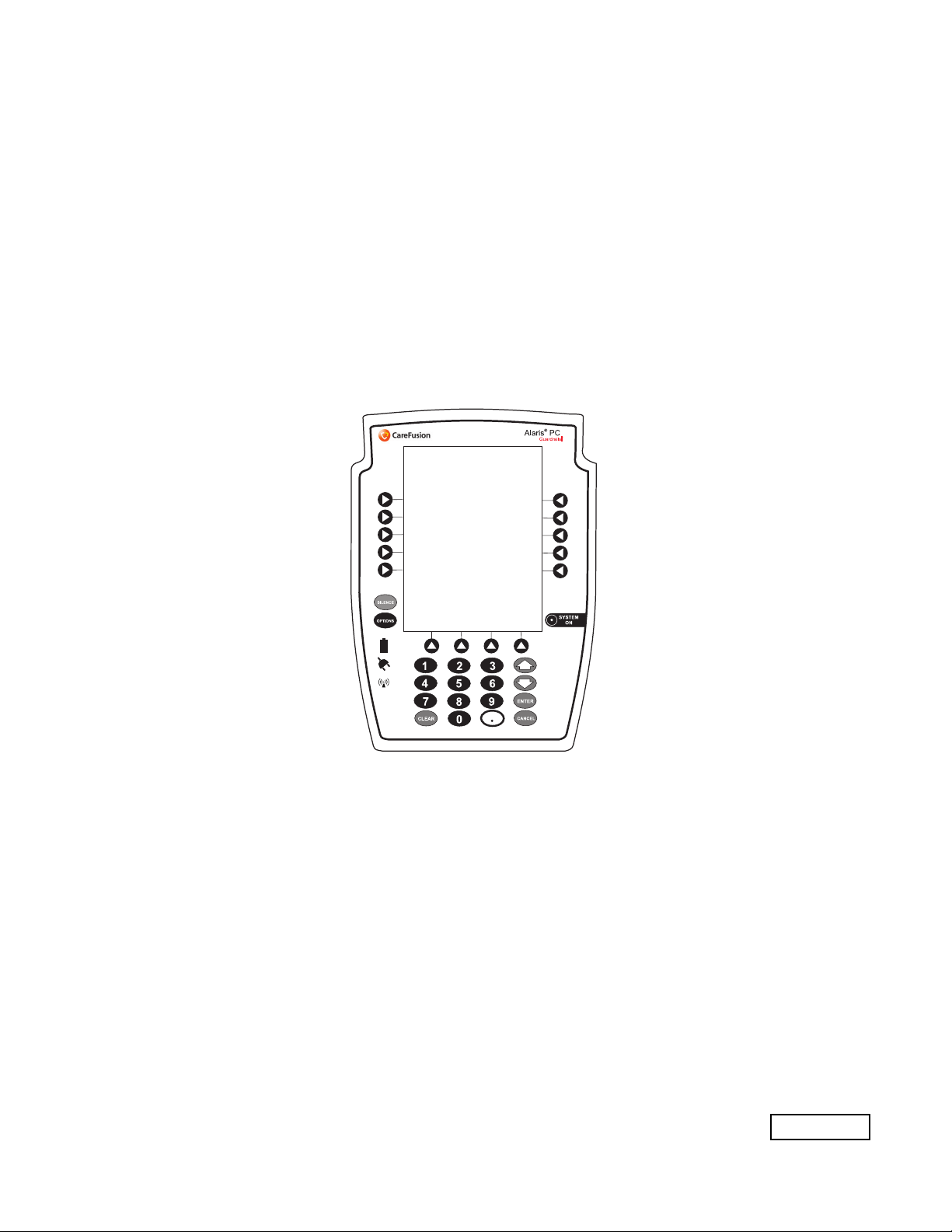
The Alaris System is a modular system intended for adult,
pediatric, and neonatal care. It consists of the PC unit, the
Guardrails™ Suite MX, and up to four detachable infusion and/
or monitoring modules (channels). The Alaris Auto-ID module
can be included as a fifth module. The use of the Alaris System
is restricted to one patient at a time.
Guardrails Suite MX for the Alaris System brings a new level of
medication error prevention to the point of patient care. The
Guardrails Suite MX features medication dosing, concentration
delivery rate, and optional initial programming guidelines for up
to 30 patient-specific care areas, referred to as Profiles. Each
Profile contains a specific Drug Library, an IV Fluid library, and
channel labels, as well as instrument configurations
appropriate for the care area. Optional drug- or IV Fluid-specific
Clinical Advisories provide visual messages. Dosing limits for
each Guardrails drug entry or rate limits for each IV Fluid entry
can be a Hard Limit that cannot be overridden during infusion
programming and/or a Soft Limit that can be overridden, based
on clinical requirements.
A Data Set is developed and approved by the facility’s
own multi-disciplinary team using the Guardrails Editor
software, the PC-based authoring tool. A Data Set is then
transferred to the Alaris System by qualified personnel. The
approved Data Sets are maintained by the Editor Software for
future updates and reference.
Information about an Alert that occurs during use is
stored within the PC unit, and can be accessed using the
Guardrails CQI Reporter software.
Documentation provided with Alaris System products
might reference product not present in your facility or not yet
available for sale in your area.
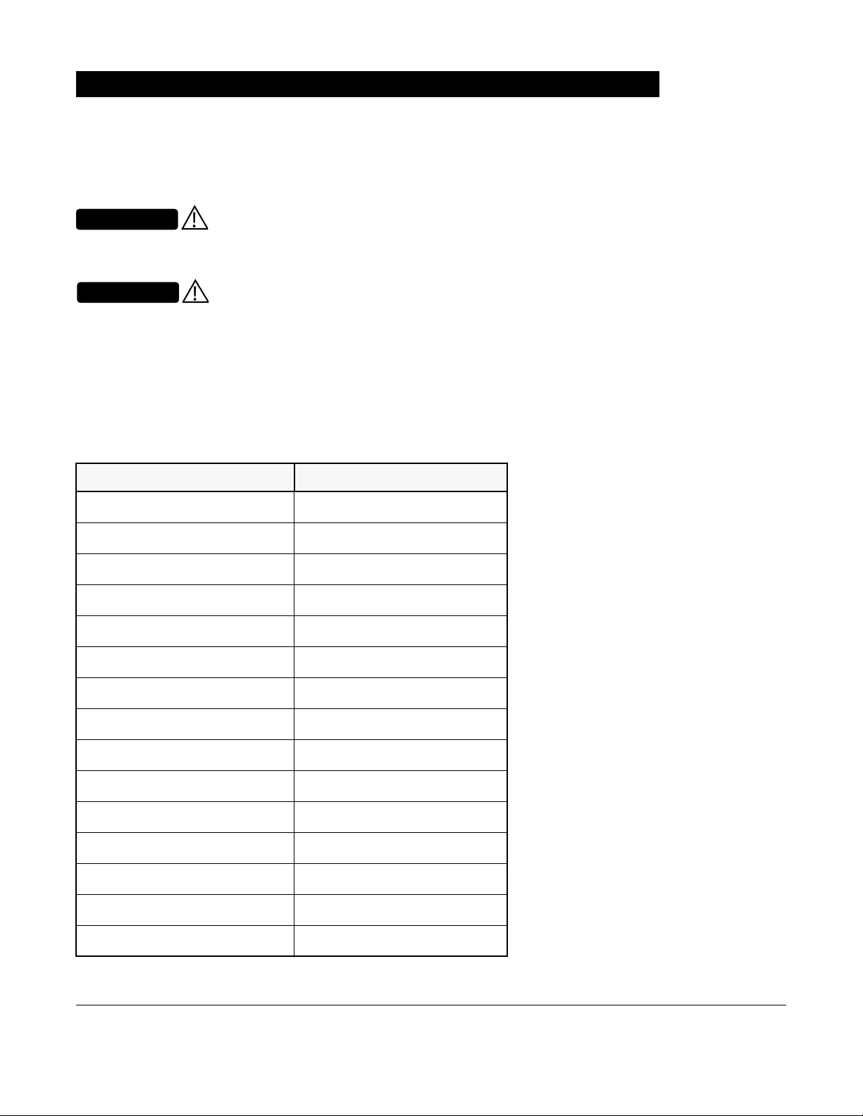
A superscript number (for example, ) identifies additional
information provided as a NOTE at the end of the procedure.
Introduction
Read all instructions before using
the Alaris System.
WARNING
nly
O
CAUTION

vi Alaris System User Manual – with v9.33 Model 8015
Intended Use
The Alaris™ System with Guardrails™ Suite MX is intended for
use in professional healthcare facilities that utilize infusion
devices for the delivery of fluids, medications, blood, and blood
products. The Alaris System with Guardrails Suite MX is
intended to provide trained healthcare caregivers a way to
automate the programming of infusion parameters, thereby
decreasing the amount of manual steps necessary to enter
infusion data.
All data entry and validation of infusion parameters is
performed by the trained healthcare professional according to a
physician's order. The Alaris System with Guardrails Suite MX
is an interoperable system capable of communicating and
exchanging data accurately, effectively, securely, and
consistently with different information technology systems,
software applications, and networks, in various settings; and
exchanging data such that the clinical or operational purpose
and meaning of the data are preserved and unaltered.
Essential Performance
The Alaris infusion modules are designed to accurately deliver
the programmed amount of the medication or fluid over the
programmed time period. The Alaris infusion modules ensure
that an infusion is not being inadvertently delivered when the
user expects the system to be in a paused, stopped, or off
condition. The Alaris infusion modules employ measurement
systems to detect and alarm for conditions adverse to safe
administration of fluid. These include measurements of proper
infusion set loading (free flow detection), pressure (occlusion
detection), and air-in-line detection.
The EtC02module will monitor and alarm when a patient
physiological condition is out of range.
The Sp02module will monitor and alarm when a patient
physiological condition is out of range
Introduction (Continued)

Alaris System User Manual – with v9.33 Model 8015 vii
WARNINGS AND CAUTIONS:
Product-specific warnings and cautions, covered in the
applicable sections of this User Manual, provide information
needed to safely and effectively use the Alaris System.
A statement that alerts the user to the
possibility of injury, death, or other serious adverse reactions
associated with the use or misuse of the device.
A statement that alerts the user to the
possibility of a problem with the device associated with the use
or misuse of the device.
DEFINED TERMS:
The following table identifies the defined terms used
throughout this document for certain trademarked products
and product features.
Introduction (Continued)
Product/Feature Defined Term
Alaris™ Auto-ID module Auto-ID module
Alaris™ EtCO2module EtCO2module
Alaris™ PCA module PCA module
Alaris™ PC unit PC unit
Alaris™ Pump module Pump module
Alaris™ SpO2module SpO2module
Alaris™ Syringe module Syringe module
Alaris™ System Maintenance System Maintenance
Alaris™ Systems Manager Systems Manager
Guardrails™ alert Alert
Guardrails™ clinical advisory Clinical Advisory
Guardrails™ CQI Reporter CQI Reporter
Guardrails™ data set Data Set
Guardrails™ drug library Drug Library
Guardrails™ Editor Editor Software
WARNING
CAUTION

viii Alaris System User Manual – with v9.33 Model 8015
CareFusion recommends the use of CareFusion manufactured
parts in the operation and maintenance of your CareFusion
equipment. Customer's use of repair or service parts, add-ons,
or disposables that are not approved by CareFusion is at
Customer's own risk and may void the product warranty
provided by CareFusion. Any 510(k) clearance from the Food
and Drug Administration (FDA) or regulatory approval secured
by CareFusion to market Alaris pumps was based on use of
only CareFusion manufactured parts and equipment. If non-
CareFusion parts, add-ons or disposables are used for the
maintenance, repair or operation of your CareFusion
equipment, those parts were not validated by CareFusion for
safety and efficacy with our Alaris products, nor were they
included in the review and approval/clearance of the products.
Instruments are tested and calibrated before they are
packaged for shipment. To ensure proper operation after
shipment, it is recommended that an incoming inspection be
performed before placing the instrument in use.
Prior to placing the Alaris System in use:
1. Perform check-in procedure using System Maintenance
software.
2. Whether or not Profiles feature has been enabled
(see PC unit section, "System Options," "System
Configurations").
Introduction (Continued)
Product/Feature Defined Term
Guardrails™ hard limit Hard Limit
Guardrails™ IV fluid IV Fluid
Guardrails™ limit Limit
Guardrails™ PCA pause
protocol
PCA Pause Protocol
Guardrails™ soft limit Soft Limit
SmartSite™ needle-free valve Needle-Free Valve
Approved Parts Recommendation
Installation
NOTE:
To enable the Profiles feature, a hospital-defined best-practice
Data Set must be uploaded to the PC unit.

Alaris System User Manual – with v9.33 Model 8015 Section 1
Alaris PC Unit
Model 8015

THIS PAGE
INTENTIONALLY
LEFT BLANK

PC Unit Section Table of Contents
Alaris System User Manual – with v9.33 Model 8015 1-iii
Getting Started
Introduction............................................................................................................................................. 1-1
General Setup and Operation
Attach and Detach Module..................................................................................................................... 1-3
Attach Module................................................................................................................................. 1-3
Detach Module ............................................................................................................................... 1-4
Add Module While System is Powered On..................................................................................... 1-5
Start-Up.................................................................................................................................................. 1-6
Power On System........................................................................................................................... 1-6
Respond to Maintenance Reminder ............................................................................................... 1-7
Adjust Display Contrast .................................................................................................................. 1-7
Select New Patient and Profile Options.......................................................................................... 1-8
Adjust Audio Volume ...................................................................................................................... 1-10
Lock/Unlock Tamper Resist............................................................................................................ 1-11
Power Off System .................................................................................................................................. 1-12
System Options ...................................................................................................................................... 1-13
Display Contrast ............................................................................................................................. 1-13
Patient ID........................................................................................................................................ 1-13
Clinician ID ..................................................................................................................................... 1-16
Power Down All Channels .............................................................................................................. 1-17
Anesthesia Mode............................................................................................................................ 1-18
Battery Runtime.............................................................................................................................. 1-21
System Configurations ................................................................................................................... 1-21
Serial Numbers............................................................................................................................... 1-23
Software Versions .......................................................................................................................... 1-24
Time of Day .................................................................................................................................... 1-25
Network Status ............................................................................................................................... 1-26
Wireless Connection....................................................................................................................... 1-29
Data Set Status .............................................................................................................................. 1-30
Maintenance Due ........................................................................................................................... 1-31
General Information
Warnings and Cautions.......................................................................................................................... 1-33
General........................................................................................................................................... 1-33
Electromagnetic Compatibility ........................................................................................................ 1-36
Features and Displays............................................................................................................................ 1-37
Features and Definitions................................................................................................................. 1-37
Operating Features, Controls, Indicators........................................................................................ 1-39
Displays .......................................................................................................................................... 1-42
System Configurable Settings................................................................................................................ 1-43
Specifications ................................................................................................................................. 1-44
Symbols.......................................................................................................................................... 1-46
Table of Contents

Table of Contents PC Unit Section
1-iv Alaris System User Manual – with v9.33 Model 8015
THIS PAGE
INTENTIONALLY
LEFT BLANK

PC Unit Section Getting Started
Alaris System User Manual – with v9.33 Model 8015 1-1
This section of the User Manual provides PC unit (Model
8015) and Alaris System instructions and information. It is used
in conjunction with:
• PC Unit/ Pump Module Technical Service Manual
• Product-specific sections of this User Manual
• System Maintenance software (and its instructions) for
Alaris System check-in, maintenance, and wireless configuration
The PC unit is the core of the Alaris System and provides
a common user interface for programming infusions and
monitoring, which helps to reduce complexity at the point of
care. The display uses color to clearly communicate critical
programming, infusion, monitoring and hospital-defined policy
information.
The wireless network card provides wireless communication
capability between the Alaris System and Alaris Systems
Manager. The combined use of the Alaris System and Alaris
Systems Manager is integrated into a facility’s existing network
infrastructure.
When enabled, the Alaris Systems Manager allows the
exchange of information between the Alaris Systems Manager
and the Alaris System. The PC unit can be operated
manually or in concert with the information exchanged with the
Alaris Systems Manager. If communication with the wireless
network is interrupted (for example, out of range), the Alaris
System can be used, as intended, in the manual mode.
Getting Started
Introduction
Read all instructions, including those
for the attached module(s) and
applicable accessories, before using
the Alaris System.
WARNING
nly
O
CAUTION

Getting Started PC Unit Section
1-2 Alaris System User Manual – with v9.33 Model 8015
Alarms and Alerts: See "Appendix A - Troubleshooting and
Maintenance" for specific PC unit alarms and alerts.
Contraindications: None known.
Electromagnetic Environment: See "Appendix" section
of this User Manual ("Regulations and Standards,"
"Compliance").
Introduction (Continued)

PC Unit Section General Setup and Operation
Alaris System User Manual – with v9.33 Model 8015 1-3
Modules can be attached to either side of the PC unit or to
either side of another module. The process to attach or detach
is the same for either side, whether attaching/detaching
to/from a PC unit or another module.
An individual hospital/facility can choose to permanently attach
modules. To remove permanently attached modules, contact
qualified service personnel.Inserting a finger or other object
into the IUI connector, when the module is attached to the PC
unit, could result in electrical shock.
The Alaris System is designed to operate a maximum of
four infusion or monitoring modules. Modules added in excess
of four are not recognized by the system. The Auto-ID module
can be included as a fifth module. A module can be attached
in any position; however, when mounted on an IV pole, it is
recommended that a balanced configuration be maintained.
Application of adhesive tape or other materials to the sides of
the PC unit and modules can prevent proper latching.
1. Position free module at a 45° angle, aligning IUI
connectors.
General Setup and Operation
Attach and Detach Module
Attach Module Inserting a finger or other object into
the IUI connector, when the module
is attached to the PC unit, could
result in electrical shock.
WARNING
45°
IUI Connector
Front View
Aligned IUI Connectors
Top View
Top View
IUI Connectors Not Aligned

General Setup and Operation PC Unit Section
1-4 Alaris System User Manual – with v9.33 Model 8015
2. Rotate free module down against PC unit or attached
module until release latch snaps in place.
1. Ensure that module is powered off before detaching.
2. Push module release latch and then rotate module up
and away from PC unit or attached module (opposite to
motion shown in "Attach Module" procedure) to disengage
connectors.
• Alaris System reidentifies and shows appropriate
module identification (A, B, C, or D), from left to right.
• Appropriate module position(s) (A, B, or C) for
remaining module(s) appear on Main Display.
Attach and Detach Module (Continued)
Attach Module (Continued)
Detach Module
When properly secured/snapped, the
release latch provides a very secure
connection between modules. If not
properly latched, a module can be
dislodged during operation.
WARNING
Release Latch
Failure to perform these operations
can result in improper instrument
operations.
WARNING
Failure to follow these instructions
may result in potential hazards
associated with damaged IUI
connectors.
WARNING

PC Unit Section General Setup and Operation
Alaris System User Manual – with v9.33 Model 8015 1-5
Add module as described in "Attach Module."
• System tests module, causing all LED segments and
indicator lights of displays to illuminate briefly.
• Appropriate module identification display (A, B, C, or D)
illuminates. Modules are always labeled left to right, so if
a module is added to left of other modules, all modules are
reidentified. Module re-identification does NOT interrupt or
affect infusion or monitoring on active modules.
• Module positions (A, B, C, or D) appear on Main Display.
• If any of the following conditions are observed, affected
module must be removed from use and inspected by
qualified personnel:
◦LED segments are not illuminated on displays during
power-on test.
◦Indicator lights do not illuminate.
◦Appropriate module identification does not appear.
Attach and Detach Module (Continued)
Add Module While System is Powered On

General Setup and Operation PC Unit Section
1-6 Alaris System User Manual – with v9.33 Model 8015
1. Connect PC unit to an external AC power source.
2. Press SYSTEM ON key.
3. System self test begins:
• Diagnostics test causes all LED display segments
and Status Indicator lights of attached module(s) to
illuminate briefly.
• Power Indicator illuminates.
• Appropriate module identification (A, B, C, or D) is
displayed on attached module(s).
• An audio tone sounds.
• If PM Reminder option is enabled and scheduled
preventive maintenance is due, MAINTENANCE
REMINDER screen appears.
• At completion of system-on test, New Patient? screen
appears.
• If either of the following conditions is observed, PC unit
or affected attached module must be removed from
use and inspected by qualified personnel:
◦System fails any part of self test.
◦Main Display does not appear backlit, appears
irregular, or has evidence of a row of pixels not
functioning properly.
Start-Up
Power On System
NOTE:
Previous infusion parameters are automatically cleared after
8 hours.
The self test provides the clinician with verification of the
operational safety and correct functioning of alarms for the
Alaris System.

PC Unit Section General Setup and Operation
Alaris System User Manual – with v9.33 Model 8015 1-7
If the
Preventive Maintenance (PM) Reminder option is enabled
and the PC unit or an attached module is due for preventive
maintenance, a MAINTENANCE REMINDER message appears
at power up. If necessary, the reminder can be temporarily
bypassed by pressing the CONFIRM soft key.
1. Notify the appropriate facility personnel when a
MAINTENANCE REMINDER occurs and remove instrument
requiring maintenance (see "Attach and Detach Module").
2. If Alaris System was powered off to replace PC unit,
reinitiate start-up process.
OR
If an attached module (such as a Pump module) was
powered off and removed, MAINTENANCE REMINDER
display reflects removal of that module. To continue
start-up process, press CONFIRM soft key.
1. Press DISPLAY CONTRAST soft key.
Start-Up (Continued)
Respond to Maintenance Reminder
Adjust Display Contrast
CONFIRM
B
MAINTENANCE REMINDER
Module(s) due for routine
preventive maintenance:
Module A:
YYYY-MM-DD
CONFIRM
B
MAINTENANCE REMINDER
Module(s) due for routine
preventive maintenance:
Midtown Hospital
Yes
No
NEW PATIENT ?
>Select Yes or No
“Yes” Clears Previous
Patient Data
DISPLAY
CONTRST

General Setup and Operation PC Unit Section
1-8 Alaris System User Manual – with v9.33 Model 8015
2. To adjust display for optimum viewing, use Lighter/Darker
soft keys.
3. To return to main screen, press CONFIRM soft key.
The following procedures assume the Profiles feature is
enabled.
1. Select required NEW PATIENT? option.
• To indicate programming is for a new patient and clear
all stored patient parameters from memory, press Yes
soft key.
• To confirm programming is for same patient and retain
all stored patient parameters, press No soft key.
◦Last used Profile is displayed.
◦If Profiles feature is disabled, main menu appears.
2. Accept or change current Profile:
• To accept current Profile, press Yes soft key.
Main screen appears.
• To change Profile, press No soft key and continue with
next step.
Profile selection screen appears.
Start-Up (Continued)
Adjust Display Contrast (Continued)
Select New Patient and Profile Options
System Options
>Adjust Display to
Desired Contrast
Display Contrast
Lighter
Darker
CONFIRM
®
Midtown Hospital
Yes
No
NEW PATIENT ?
>Select Yes or No
“Yes” Clears Previous
Patient Data
DISPLAY
CONTRST
Midtown Hospital
Adult ICU
Yes
No
>Select Yes or No
Adult ICU ?
“Yes” Confirms Same
Profile
Other manuals for Alaris 8015
1
This manual suits for next models
7
Table of contents