Carimali AVRISP mkII Owner's manual
LB-00145-55
Pag. 1
TECHNICAL
INSTRUCTIONS
TECHNICAL
INSTRUCTIONS
AVR USB PROGRAMMER
With Atmel AVR Studio
6.1
EN - ENGLISH
LB-00145-55
EDITION MARCH 2016
www.carimali.com

LB-00145-55
Pag. 2
SOMMARIO
INTRODUCTION AND GENERAL INSTRUCTIONS................................................................3
AVR STUDIO 6.1 AND SUB-PROGRAM INSTALLATION......................................................5
FIRMWARE AVRISPmkII UPGRADE.......................................................................................10
MANUAL FIRMWARE UPDATE OF AVRISP mkII................................................................11
CARIMALI MAIN BOARD...........................................................................................................12
AVRISPmkII – MAIN BOARD CONNECTION.........................................................................16
FIRMWARE UPDATE PC TO MACHINE MAINBOARD...................................................17
MACHINE SET-UP DATA READING ...................................................................................18
MACHINE SET-UP DATA WRITE.......................................................................................19
MACHINE MAIN BOARD ERASE..............................................................................................20
TROUBLESHOOTING ..................................................................................................................21
LB-00145-55
Pag. 3
INTRODUCTION AND GENERAL INSTRUCTIONS
The AVR USB programmer allows to carry out the following operation:
1. program the microprocessor on the machine master board with the machine software, file.hex;
2. transfer to the laptop the machine settings file (dose settings, counters...);
3. transfer the above mentioned file to another machine microprocessor;
4. format the microprocessor.
tmel Studio 6.1 is based on Microsoft .NET 4.0 technology and is thus Windows software. The supported software
platforms are listed below.
•Windows XP (x86) with Service Pack 3 - all editions except Starter Edition
•Windows Vista (x86 & x64) with Service Pack 2 - all editions except Starter Edition
•Windows 7 (x86 & x64)
•Windows 8 ( x64 )
•Windows Server 2003 (x86 & x64) with Service Pack 2
•Windows Server 2003 R2 (x86 & x64)
•Windows Server 2008 (x86 & x64) with Service Pack 2
•Windows Server 2008 R2 (x64)
Recommended hardware:
•1.6GHz processor or faster
•DirectX 9 capable video card running at 1024x768 resolution (minimum 800x600 screen)
•1 GB (32 Bit) or 2 GB (64 Bit) R M ( dd 512 MB if running in a virtual machine)
•5400 RPM hard disk drive
•2 GB free hard disk space
•1 port USB 2.0
We always recommend to have the latest OS versions and Service packs installed. We also recommend Internet
Explorer 7 or later.
Software:
ATMEL: AVR Studio .1
LB-00145-55
Pag. 4
INTRODUCTION AND GENERAL INSTRUCTIONS
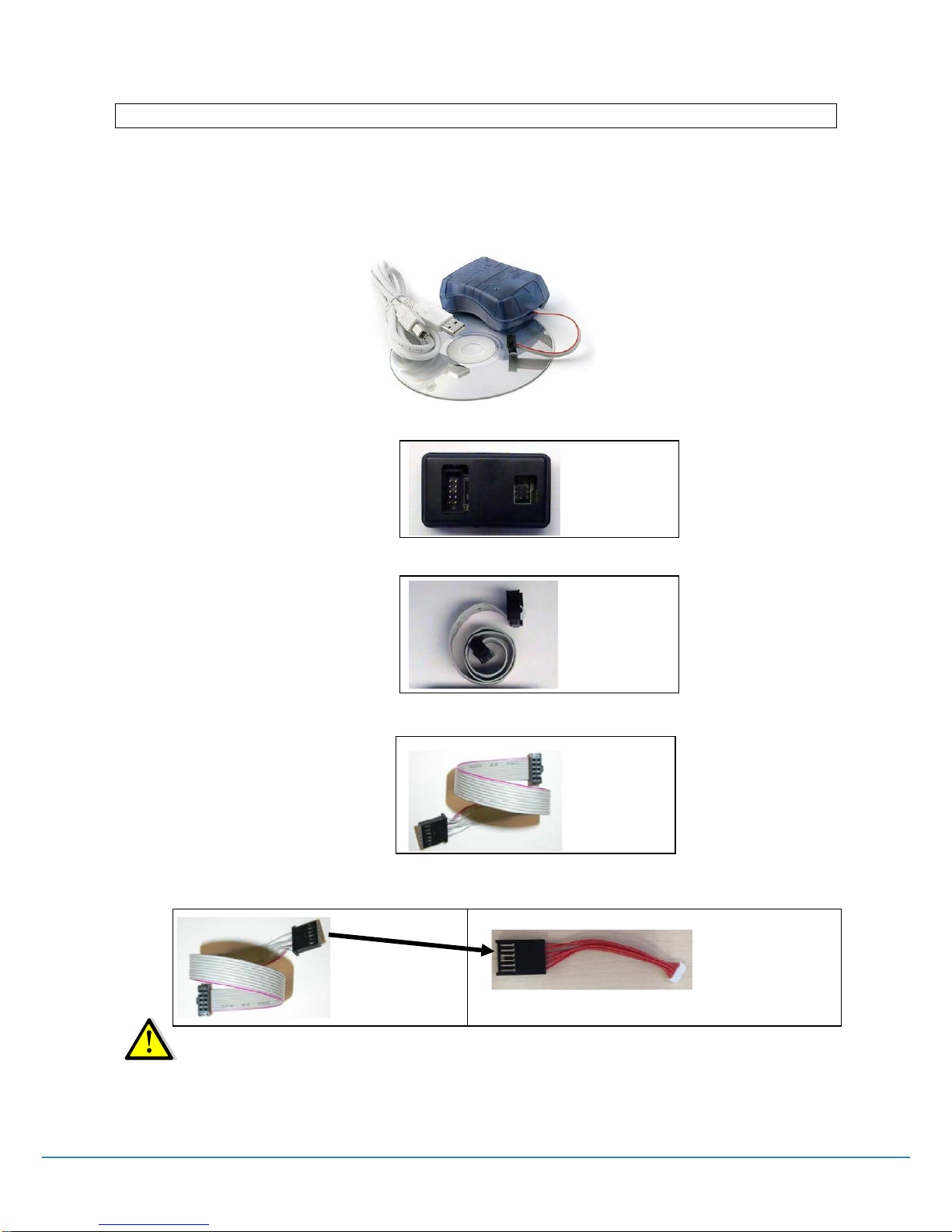
The kit code -04.00828- Includes:
a. 1x CD-ROM containing: a folder with the installation software on PC, and the technical manual
b. 1x Master board VRISP mkII complete with cable 3x2 pin;
c. 1x Cable to connect the VRISP mkII to a laptop USB port;
The items referring to a. b. c. can be separately supplied with code 96.00765.L1, see the following picture:
d. 1x interface board between the VRISP mkII and the machine master board with microprocessor tmega.
e. 1x cable 10x2 PIN, to connect the interface board ref. d. and the machine master board with microprocessor
Tmega32 / 644 / 128 / 2560.
f. 1x cable 10x2 to 6 PIN, to connect the interface board ref. d. and the machine master board with microprocessor
Tmega168P.
g. 1x cable 6 PINs to be connected in series to the cable 03.05036 (ref. f.), used to connect the interface board
ref. d. and the machine master board with microprocessor Tmega2560.
NOTE: VR Studio 6.1 and the USB driver must be installed before VRISP mkII is connected to the pc.
code 96.00773
code 03.01082
code 03.05036
code 03.05201
code 03.05036
LB-00145-55
Pag. 5
AVR STUDIO 6.1 AND SUB-PROGRAM INSTALLATION
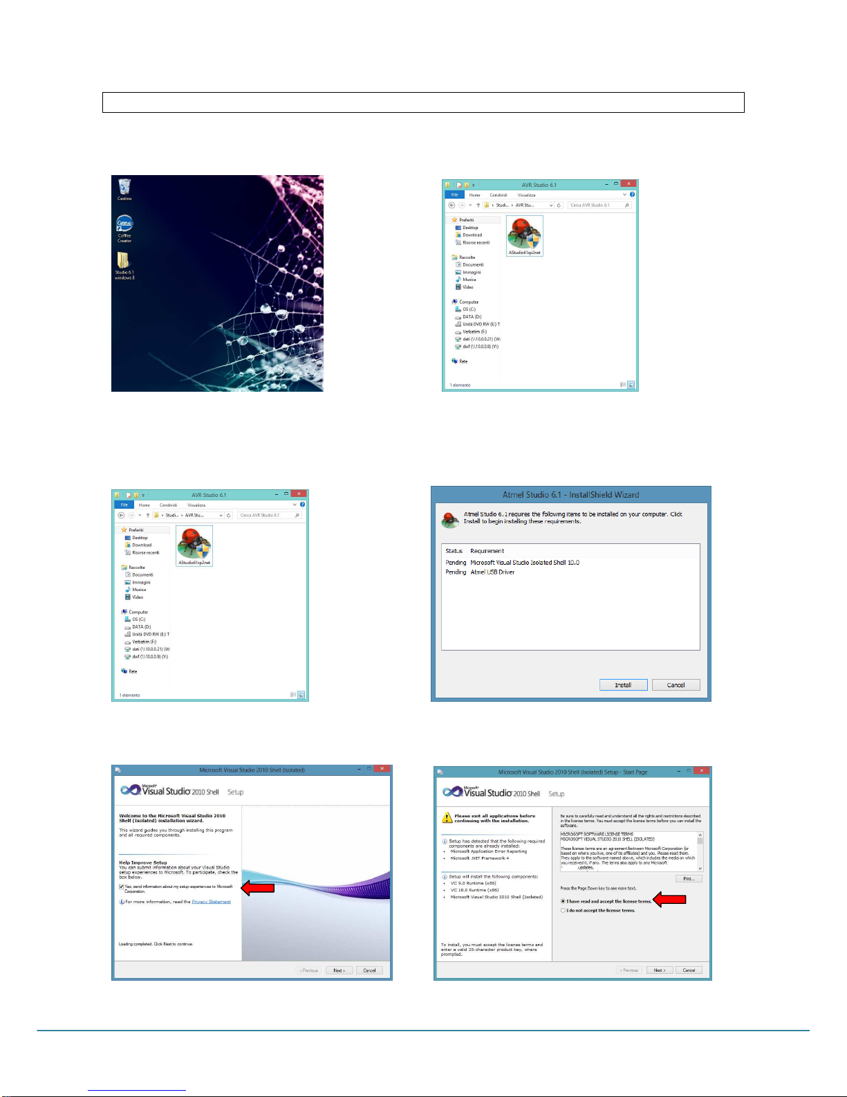
Insert the CD-ROM / USB pen drive in the reader and open the folder CD-1.09 (or later version).
Picture 1.1 Picture 1.2
Open the folder Studio 6.1:
Carry out the Studio61sp2net [or later version] by clicking twice the icon [Picture 1.3]
Click Install [Picture 1.4]
Picture 1.3 Picture 1.4
Remove the checkmark in the box [ Picture 1.5],accept the license terms then press Next [Picture 1.6].
Picture 1.5 Picture 1.6
LB-00145-55
Pag. 6
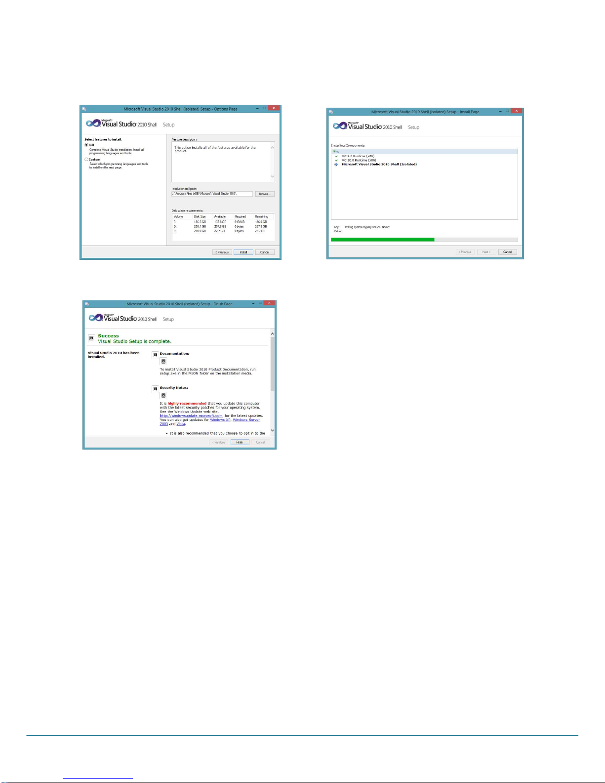
Select the Full feature and the path in which the setup will install the Visual Studio 2010 Shell [Picture 1.7].
Press Install to start the installation.[Picture 1.8].
Picture 1.7 Picture 1.8
Press “Finish” to end the Visual Studio 2010 installation [Picture 1.9
Picture 1.9
LB-00145-55
Pag. 7
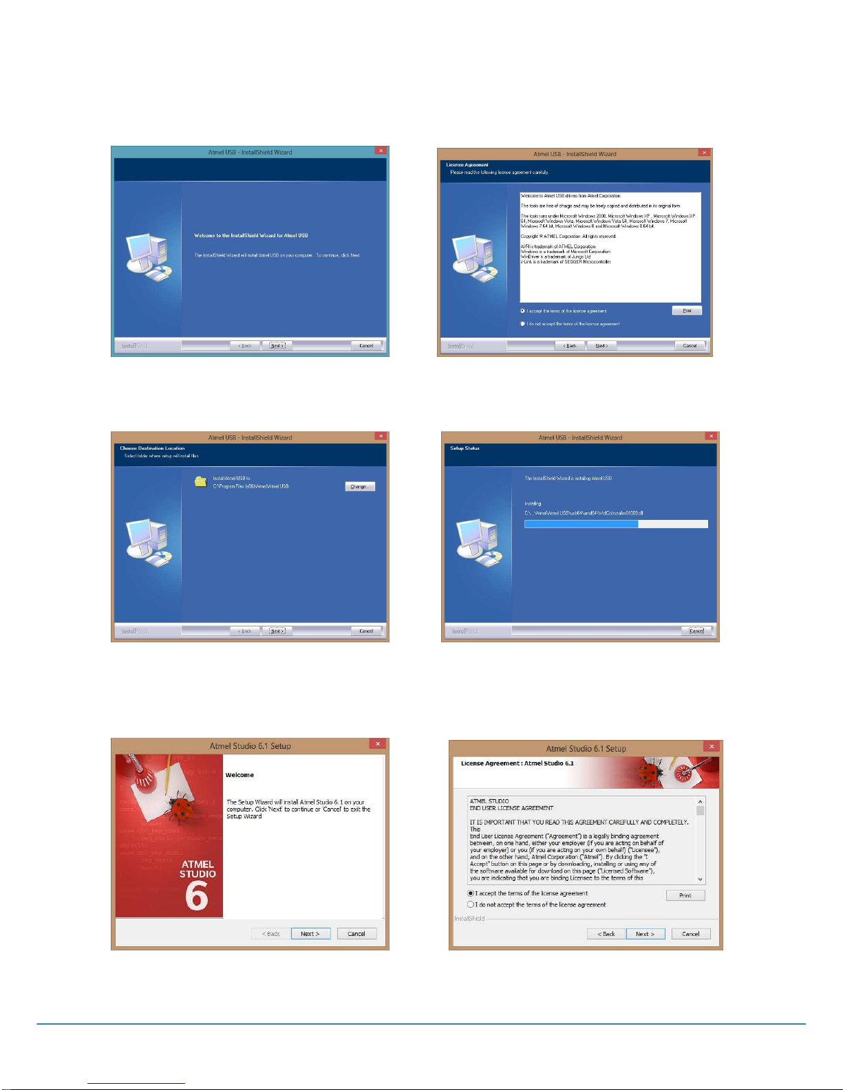
Press Next to start the vr Jungo Usb installation [Picture 2.2]
ccept the terms licence agreement and click Next [Picture 2.3 ]
Picture 2.2 Picture 2.3
Click next then install to begin the installation[Picture 2.4 ] wait for the completion of the installation then press finish
[Picture 2.5 ]
Picture 2.4 Picture 2.5
The wizzard Setup will install the vr Studio 6.1, Click Next to start [ Picture 2.6 ]. ccept the terms licence agreement
and click Next [Picture 2.7 ]
Picture 2.6 Picture 2.7

LB-00145-55
Pag. 8
Specify the folder where vr Studio 6.1 will be installed [ Picture 2.8 ].
Picture 2.8
Setup has enough information to start copying the files, if you are not sure about the setting press Back.If you are
satisfied with the setting click Next.[ Picture 2.9 ] wait for the completion of the installation [ Picture 3.0 ]
Picture 2.9 Picture 3.0
Remove the checkmark in the ssociate files box then press Finish to end the vr Studio 6.1 installation [ Picture 3.1 ]
Picture 3.1
LB-00145-55
Pag. 9
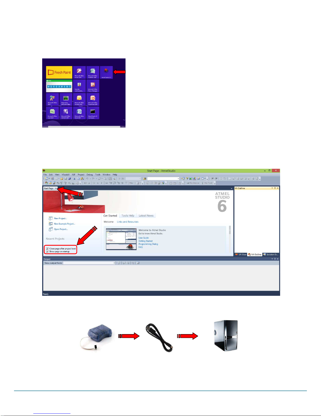
In the menu ST RT –Click twice the VR Studio 6.1 icon to open it [Picture 3.2].
Picture 3.2
The following window will be shown:
Remove the checkmark from “Close page after project load” and “Show page at start-up”, then close the Start Page
[Picture 3.3]
Picture 3.3
Connect the VRISPmkII to PC USB port through the supplied cable. The PC will automatically start the hardware
installation procedure of the VRISP mkII.

LB-00145-55
Pag. 10
FIRMWARE AVRISPmkII UPGRADE
VR Studio 6.1 will contain the latest firmware available from tmel. VR Studio after connecting the VR, system
may require an firmware update.
Press “Yes” [ Picture 3.4 ], then “upgrade” to start the upgrade procedure[ Picture 3.5 ].
Picture 3.5
Wait until the progress bar fills up [ Picture 3.6 ].Press “close” to end the upgrade [ Picture 3.7 ].
Picture 3.6 Picture 3.7
Disconnect and reconnect the VR programmer from/to the PC USB: if the led turned toward the USB port
[ Picture 3.8 ] will get green, the programmer installation has been succesfull.
Picture 3.8 Picture 3.9
For some of Atmega master boards, it will be necessary to use the adaptor code 9 .00773
[Picture 3.9] supplied with the Kit Avr isp mkII.
Picture 3.4
Table of contents
Other Carimali Motherboard manuals


