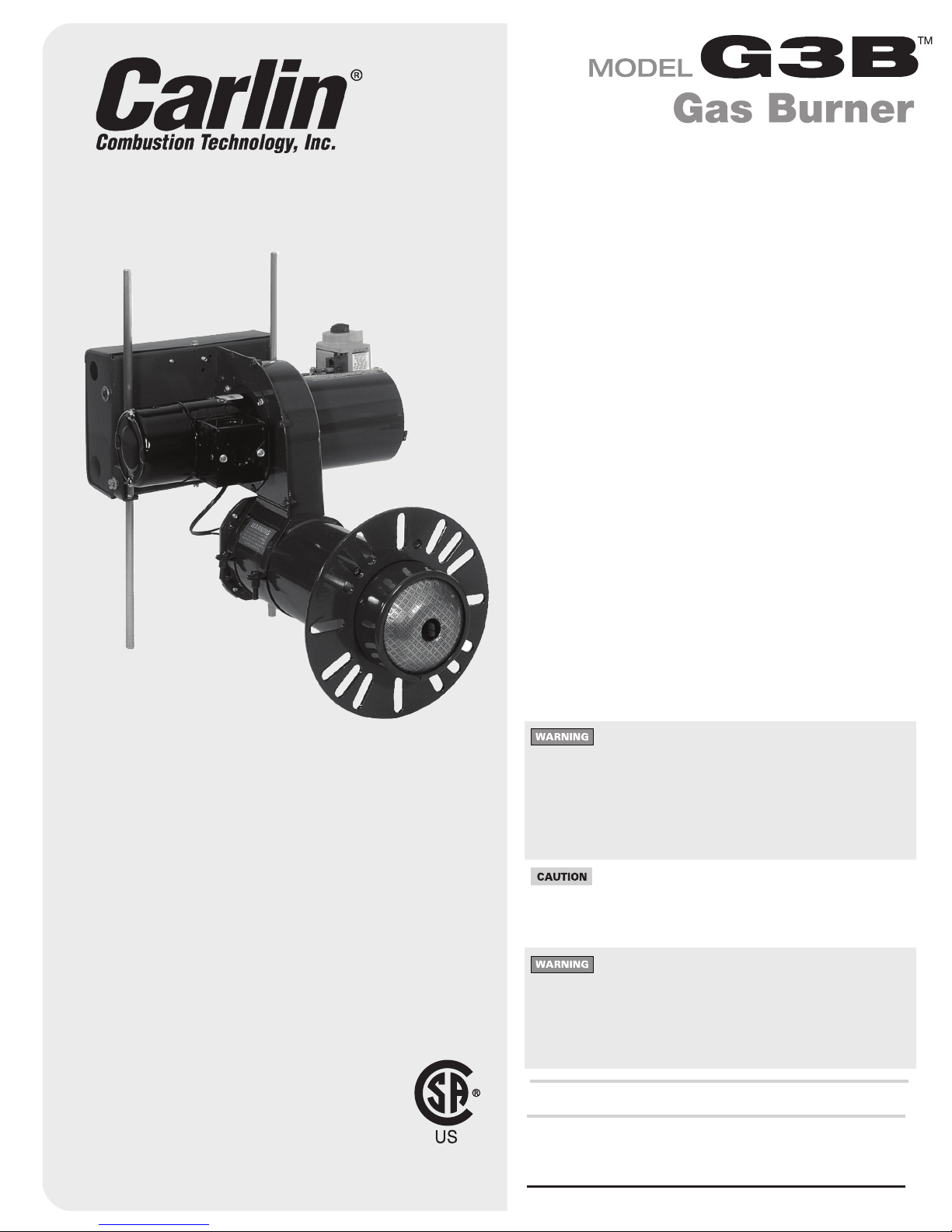
Model G3B Gas burner — Instruction manual
MNG3B Gas 041015
8
1. Prepare Site • Prepare Burner • Mount Burner (continued)
Mount burner in appliance
• Verifyapplianceburnerfrontplatedimensionsperpage21.
• Slidegasketsuppliedwithburneroverendofairtube.
• Insertburnerintoapplianceopeningandboltinplace.
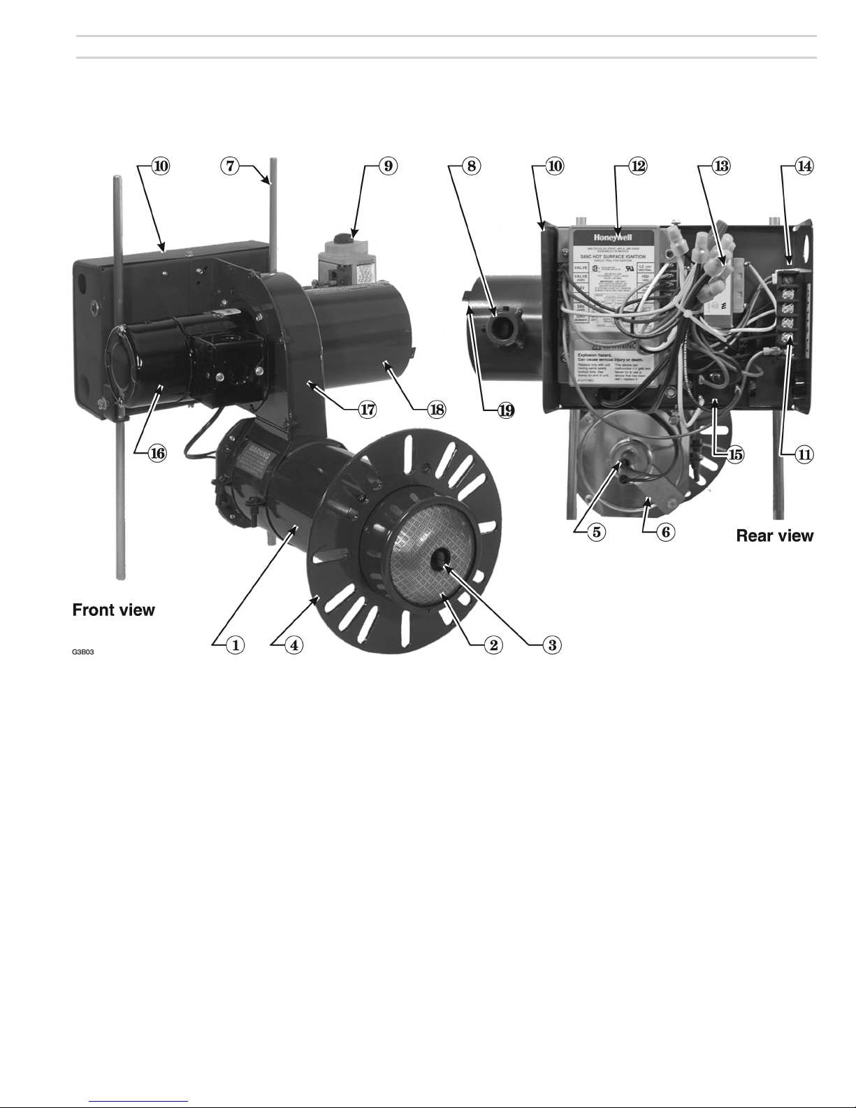
Inspect burner and components
Drill or ream gas orifice to size (initial installation)
You must disconnect power to burner and close main manual
gas valve before proceeding. Failure to do so could result
in severe personal injury, death or substantial property
damage.
You must drill or ream the burner orifice to the size given in
Figure 4.The orifice is shipped with a pilot hole only. Firing the
burner with the orifice as shipped can result in damage to the
burner.NeverretheG3Bburnerbelow60,000Btuhinput.
The flameholder can overheat, resulting in potential severe
personal injury, death or substantial property damage.
1. After drilling or reaming orifice to correct size, thread orifice fitting into
orifice nipple as shown in Figure 4.
Install gas valve on burner
1. Read WARNING’s on page 9 before installing gas valve.
2. Applyasmallamountofpipedope(suitableforpropanegas)togas
valve outlet connection, gas line elbow and orifice nipple. Assemble
elbow and orifice nipple to gas valve.
To avoid damage to gas valve, do not hold valve with a pipe
wrench or over-tighten. Use only a crescent wrench or other
means. Failure to comply could result in severe personal
injury, death or substantial property damage.
3. Insert orifice nipple into burner gas connection and secure in place
using the two Allen screws.
4. Connect gas valve wires to gas valve.
Inspect/redrill gas orifice when required
1. Turnoffpowertotheburner/appliancebeforeproceeding.
2. Closemainmanualgasvalveingaslinetoburner.Thendisconnectthe
ground joint union to allow rotating burner combination gas valve.
You must disconnect power to burner and close main manual
gas valve before proceeding. Failure to do so could result
in severe personal injury, death or substantial property
damage.
3. LoosenAllenscrewssecuringgaslinetoburnergasconnection.
4. Remove combination gas valve (item 9, page 3) and gas piping to burner
gasconnection(item8,page3)onburnerairtube.
5. ReadcorrectoricedrillsizefromFigure4.Thencheckactualorice
size using that size twist drill bit.
• If gas orifice is smaller than required, redrill orifice to correct size,
ifnecessary.Replacegasvalveandpiping,usingonlypipedopelisted
forusewithliqueedpetroleumgases.
• If gas orifice is larger than required, obtain a replacement gas orifice
fitting. Drill orifice hole in replacement orifice fitting.
Hot surface ignitor
• Inspecttheburnerfromairtubeend.Thehotsurfaceignitormustextend
slightlypasttheendoftheburner.
• Carefullyinspecttheignitor,ensuringitisintact,withnocracksorvisual
signsofdegradation.
• Donottouchtheignitorwithbarehands.Bodyoilscancausedeterioration
ofthesiliconcarbide.
• Replaceignitorifthereareanysignsofdamage.
You must allow ignitor to cool before attempting to handle.
Failure to do so could result in severe personal injury or
damage to the ignitor.
Inspect components and wiring
• Visuallyinspectallburnercomponentsandwiring.
• Verifythatwiringisintactandleadsaresecurelyconnected.
• Verifythatallburnercomponentsareingoodcondition.
Figure 4 Orifice and gas valve installation
Input
Btuh
Burner orifice drill size
Diameter, inches
Air throttle
turns (appr.)
Notes 1 & 2
Note 1 Natural Gas Propane Gas
60,000 #28 (0.141) #33 (0.113) 0
70,000 #24 (0.152) Z\, (0.125) ½
80,000 #20 (0.161) #30 (0.129) ¾
90,000 #17 (0.173) #28 (0.141) 1
100,000 #14 (0.182) #25 (0.150) 1½
110,000 #11 (0.191) #22 (0.157) 1¾
120,000 #7 (0.201) #20 (0.161) 2¼
140,000 #3 (0.213) #16 (0.177) 3
160,000 A (0.234) #12 (0.189) 4¼
180,000 D (0.246) #7 (0.201) 9
Note 1: High altitude applications: The maximum burner input at sea level is 180,000 Btuh.
Reduce this capacity by 4% per 1,000 feet above sea level. Example — max.
capacity at 5,000 feet is 144,000 Btuh (20% reduction).
Note2: Usethisasthestartingsettingonly.Adjustairthrottle,ifnecessary,afterperforming
combustion testing (see page 14).