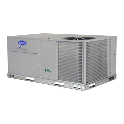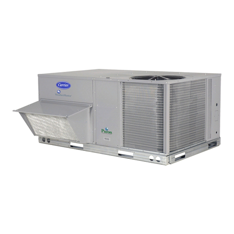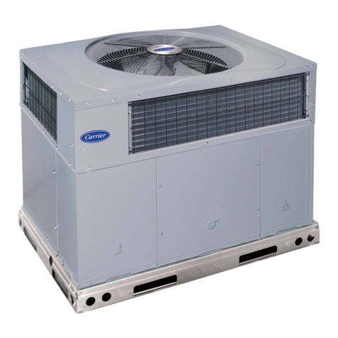
48PG03-07
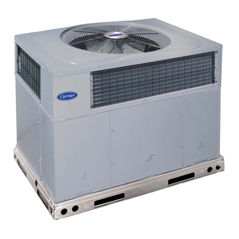
Single Package Rooftop Units
Electric Cooling/Gas Heating
with PURON® (R-410A) Refrigerant
and Electromechanical Controls
Installation, Start-Up, and
Service Instructions
CONTENTS
Page
SAFETY CONSIDERATIONS ....................... 1,2
INSTALLATION ................................... 2-19
Step 1-- Plan for Unit Location ..................... 2
Step 2 -- Provide Unit Support ...................... 2
• ROOF CURB
• ALTERNATE UNIT SUPPORT
Step 3 -- Rig and Place Unit ......................... 2
• INSTALLATION ONTO CURB
• SLAB MOUNT (Horizontal Units Only)
Step 4 -- Field Fabricate Ductwork .................. 4
Step 5 -- Make Unit Duct Connections .............. 4
Step 6 -- Install Flue Hood and Inlet Hood ........... 7
Step 7 -- Install External Trap
for Condensate Drain .............................. 8
Step 8 -- Install Gas Piping .......................... 9
Step 9 -- Make Electrical Connections .............. 9
•FIELD POWER SUPPLY
• FIELD CONTROL WIRING
Step 10 -- Optional EconoMi$er IV ................. 13
Step 11 -- Install All Accessories ................... 19
PR E-START-U P..................................... 20
START-UP ....................................... 20-36
SERVICE ........................................ 37-45
Cleaning ............................................ 37
Lubrication ......................................... 38
Evaporator Fan Service and Replacement .......... 39
Evaporator Fan Performance Adjustment ........... 39
Evaporator Fan Belt Tension Adjustment ........... 39
Condenser-Fan Adjustment ........................ 39
Verify Sensor Performance ......................... 40
Economizer Operation During Power Failure ....... 40
Evacuation ......................................... 40
Refrigerant Charge ................................. 40
Gas Valve Adjustment .............................. 42
High Altitude ....................................... 42
LP (Liquid Propane) Gas Use ....................... 42
Main Burners ....................................... 42
Filter Drier .......................................... 43
Protective Devices .................................. 43
Relief Devices ...................................... 43
Control Circuit 24-V ................................ 43
Replacement Parts ................................. 43
Diagnostic LEDs .................................... 43
TROU BLESHOOTING ............................ 46-49
Unit Troubleshooting ............................... 46
EconoMi$er IV Troubleshooting .................... 48
Phase Loss Protection ............................. 49
UNIT START-UP CHECKLIST ..................... CL-I
SAFETY CONSIDERATIONS
Installation and servicing of air-conditioning equipment can
be hazardous due to system pressure and electtic_d components.
Only trained and qu_dified service personnel should inst_dl,
repair, or service air-conditioning equipment.
Untrained personnel can perform the basic maintenance
functions of cleaning coils and filters and replacing filters. All
other operations should be performed by trained service per-
sonnel. When working on air-conditioning equipment, observe
precautions in the literature, tags and labels attached to the unit,
and other safety precautions that may apply.
Follow all safety codes. Wear safety glasses and work
gloves. Use quenching cloth for unbrazing operations. Have
fire extinguishers available for _dl brazing operations.
Before performing service or maintenance operations on
unit, turn off main power switch to unit. Electrical shock
could cause personal injury.
Puron (R-410A) refrigerant systems operate at higher pres-
sures than stan&trd R-22 systems. Do not use R-22 service
equipment or components on Puron refrigerant equipment.
If service equipment is not rated for Puron refrigerant,
equipment dmnage or personal injury may result.
1. [mproper inst_dlation, adjustment, alteration, service,
or maintenance can cause property &Lmage, personal
injury, or loss of life. Refer to the User's Information
Manual provided with this unit for mote details.
2. Do not store or use gasoline or other flammable
vapors and liquids in the vicinity of this or any other
appliance.
What to do if you smell gas:
1. DO NOT try to light any appliance.
2. DO NOT touch any electrical switch, or use any
phone in your building.
3. IMMEDIATELY call your gas supplier from a neigh-
bor's phone. Follow the gas supplier's instructions.
4. If you cannot reach your gas supplier, c_dl the fire
department.
Disconnect gas piping flom unit when pressure testing at
pressure greater than 0.5 psig. Pressures greater than
0.5 psig will cause gas valve damage resulting in haztudous
condition. [f gas valve is subjected to pressure greater than
0.5 psig, it must be replaced before use. When pressure
testing field-supplied gas piping at pressures of 0.5 psig or
less, a unit connected to such piping must be isolated by
closing the manual gas valve(s).
Manufacturer reserves the right to discontinue, or change at any time, specifications or designs without notice and without incurring obligations.
PC 111 Catalog No. 534-80209 Printed in U.S,A, Form 48PG-8SI Pg 1 8-05 Replaces: New
