manuals.online logo
Brands
  1. Home
  2. •
  3. Brands
  4. •
  5. Carrier
  6. •
  7. Air Conditioner
  8. •
  9. Carrier 50GS030 Guide Instructions and recipes

Carrier 50GS030 Guide Instructions and recipes

50GS, 50GX
3-Phase Single-Packaged Air Conditioners
Visit _r_r_r+C"_Irrier+_"o[n
Installation, Start-Up, and Operating instructions
50GS,GX Sizes 030=060
HEATING & COOLING
NOTE: Read the entire instruction manual belk_re starting the
installation.
This symbol --> indicates a change since the last issue.
TABLE OF CONTENTS
SAFETY CONSIDERATIONS ..................................................... l
Introduction .................................................................................... 2
RECEIVING AND INSTALLATION .......................................... 2
Check Equipment ...................................................................... 2
IDENTIFY UNIT ................................................................ 2
INSPECT SHIPMENT ........................................................ 2
Provide Unit Support ................................................................ 2
ROOF CURB ....................................................................... 2
SLAB MOUNT ................................................................... 2
GROUND MOUNT ............................................................ 2
Provide Clearances .................................................................... 2
Field Fabricate Ductwork ......................................................... 2
Rig and Place Unit .................................................................... 2
INSPECTION ...................................................................... 7
INSTALLATION ................................................................ 7
Connect Condensate Drain ....................................................... 7
Install Duct Connections .......................................................... 8
CONFIGURING UNITS FOR DOWNFLOW (VERTI-
CAL) DISCHARGE ............................................................ 8
Install Electrical Connection .................................................... 9
HIGH-VOLTAGE CONNECTIONS ................................ lI)
SPECIAL PROCEDURES FOR 208-V OPERATION ...lI)
CONTROL VOLTAGE CONNECTIONS ....................... lI)
STANDARD CONNECTION .......................................... 11
TRANSFORMER PROTECTION .................................... 11
PRE-START-UP .......................................................................... 13
START-UP ................................................................................... 13
CHECK FOR REFRIGERANT LEAKS .......................... 13
START LIPCOOLING SECTION AND MAKE ADJUST-
MENTS .............................................................................. 13
CHECKING COOLING CONTROL OPERATION ....... 13
CHECKING AND ADJUSTING REFRIGERANT
CHARGE ........................................................................... 14
INDOOR AIRFLOW AND AIRFLOW ADJUST-
MENTS .............................................................................. 14
For 2081230V ..................................................................... 14
FOR 460-V GE MOTORS ................................................ 14
COOLING SEQUENCE OF OPERATION ..................... 14
MAINTENANCE ......................................................................... 17
AIR FILTER ...................................................................... 20
EVAPORATOR BLOWER AND MOTOR ..................... 21
CONDENSER COIL EVAPORATOR COIL, AND CON-
DENSATE DRAIN PAN .................................................. 21
CONDENSER FAN .......................................................... 22
ELECTRICAL CONTROLS AND WIRING .................. 22
REFRIGERANT CIRCUIT ............................................... 22
EVAPORATOR AIRFLOW ............................................. 22
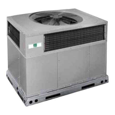
C99001
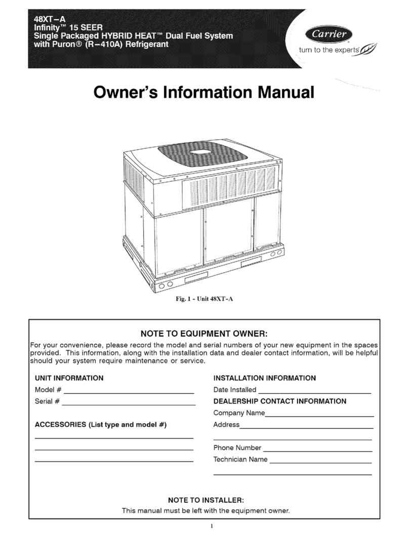
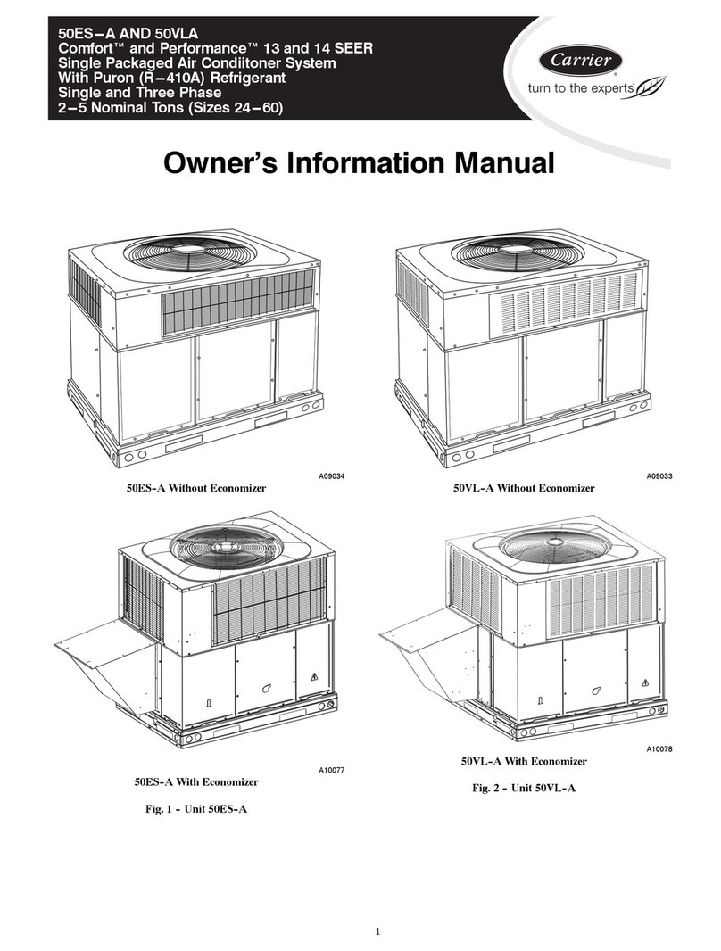
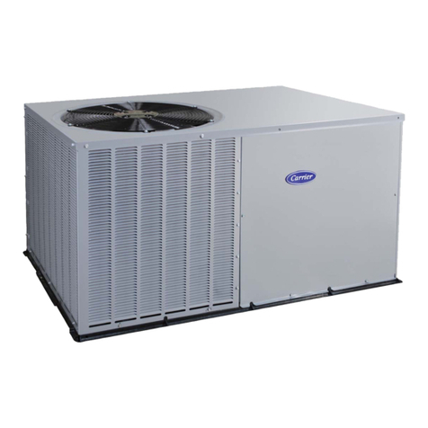
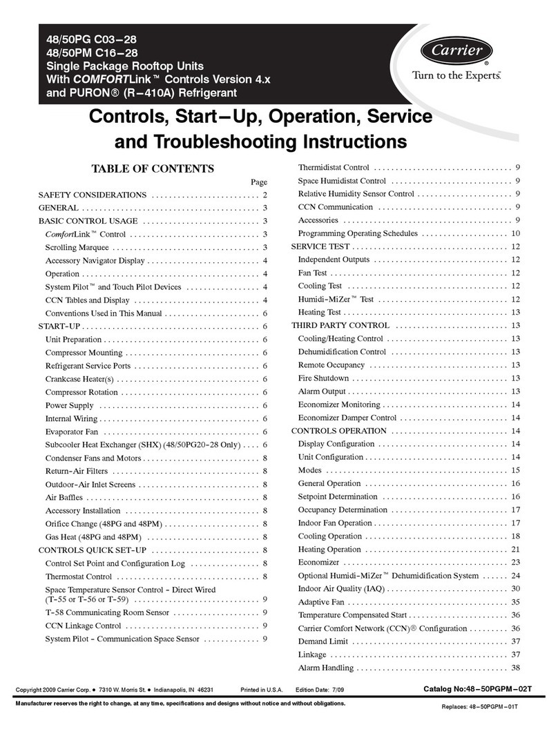
Fig. liUnit 50GS and 50GX
METERING DEVICE ACUTROL DEVICE ............. 22
LIQUID LINE STRAINER .............................................. 22
Troubleshooting ............................................................................ 22
Start-Up Checklist ........................................................................ 22
NOTE TO INSTALLER Belk_rethe installation, READ THESE
INSTRUCTIONS CAREFULLY AND COMPLETELY. Also,
make sure the User's Manual and Replacement Guide are leli with
the unit after installation.
SAFETY CONSiDERATiONS
Installation and servicing of air-conditioning equipment can be
hazardous due to system pressure and electrical components. Only
trained and qualilied personnel should install, repair, or service
air-conditioning equipment.
Untrained personnel can perli_rm basic maintenance l_.lnctions of
cleaning coils and lilters. All other operations should be perlormed
by trained service personnel. When working on air-conditioning
equipment, observe precautions in the literature, tags, and labels
attached to the uniL and other sali_ty precautions that may apply.
Follow all sali_ty codes. Wear salbty glasses and work gloves. Use
quenching cloth lor unbrazing operations. Have fire extinguisher
available lkn"all brazing operations. Consult a qualified installer or
service agency lin" inli_rmation or assistance. The qualified in-
staller or agency must use only factory-authorized kits or acces-
sories when modifying this product.
Manufacturer reserves the right to discontinue, or change at any time, specifications or designs without notice and without incurring obligations.
PC 101 Printed in U.S.A. Catalog No. 50GS-4SI Pg 1 2-06 Replaces: New
Belk_re pel'fl_rming service or maintenance operations on
system, turn o1"1power to unit. Turn off accessory heater
power switch, if applicable. Electrical shock can cause
personal injury.
Recognize salety in%rmation. This is the sali:ty-alert symbol/_ .
When you see this symbol in instructions or manuals, be alert to
the potential lk_rpersonal injury.
Understand the signal words DANGER, WARNING, CAUTION,
and NOTE. These words are used with the sali:ty-alert symbol.
DANGER identifies the most serious hazards which will result in
severe personal injury or death. WARNING signifies a hazard
which could result in personal injury or death. CAUTION is used
to identily unsali: practices which would result in minor personal
injury or product and property damage. NOTE is used to highlight
suggestions which will result in enhanced installation, reliability,
or operation.
These instructions cover mininmm requirements and conli_rm to
existing national standards and salety codes. In some instances,
these instructions exceed certain local codes and ordinances,
especially those that may not have kept tapwith changing residen-
tial construction practices. We require these instructions as a
mininmm lk_ra salt: installation.
iNTRODUCTiON
The 50GS and 50GX units (see Fig. 1)are fully sellCcontained, and
designed Ik_r outdoor installation. See Figs. 2 and 3 Ik_r unit
dimensions. All unit sizes have discharge openings liar both
horizontal and downflow conl'igurations, and are factory shipped
with all downflow duct openings covered . Units may be installed
either on a rooftop, ground-level cement slab, or directly on the
ground if local codes permit. (See Fig. 4A Ii}l"roof curb dimen-
sions.)
RECEIVING AND INSTALLATION
Step liCheck Equipment
IDENTIFY UNIT
The unit model number and serial number are stamped on the unit
identification plate. Check this inli_rmation against shipping pa-
pers.
INSPECT SHIPMENT
Inspect liar shipping damage while unit is still on shipping pallet.
11'unit appears to be damaged or is torn loose fi'ona its anchorage,
have it examined by transportation inspectors belk)re removah
Forward claim papers directly to transportation company. Manu-
facturer is not responsible lk)r any damage incurred in transit.
Check all items against shipping list. Immediately notify the
nearest Carrier Air Conditioning olTice if' any item is missing. To
prevent loss or damage, leave all parts in original packages until
installation.
Step 2iprovide Unit Support
ROOF CURB
Install accessory roof curb in accordance with instructions shipped
with curb (See Fig. 4A). Install insulation, cant strips, roofing, and
flashing. Ductwork must be attached to curb.
IMPORTANT: The gasketing of the unit to the roof curb is critical
liar a watertight seal. Install gasketing material supplied with the
roof curb. hnproperly applied gasketing also can result in air leaks
and poor unit perlormance.
Curb should be level to within 1/4 in. (See Fig. 5A). This is
necessary liar unit drain to function properly. Relier to accessory
roof curb installation instructions lk_r additional inlk_rmation as
required.
SLAB MOUNT
Place the unit on a solid, level concrete pad that is a nfininmm of
4 in. thick with 2in. above grade (See Fig. 5B). The slab should
extend approximately 2 in. beyond the casing on all 4 sides of the
unit. Do not secure the unit to the slab e.rcvpt when required by
local codes.
GROUND MOUNT
The unit may be installed either on a slab or placed directly on the
ground if' local codes permit. Place the unit on level ground
prepared with gravel liar condensate discharge.
Step a--Provide Clearances
The required minimum service clearances are shown in Fig. 2 & 3.
Adequate ventilation and outdoor air lnust be provided. The
outdoor fan draws air through the outdoor coil and discharges it
through the top fan grille. Be stare that the fan discharge does not
recirculate to the outdoor coil. Do not locate the unit in either a
corner or under an overhead obstruction. The minimum clearance
under a partial overhang (such as a normal house overhang) is 36
in. above the unit top. The maximum horizontal extension of a
partial overhang lnust not exceed 48 in. For extended overhangs,
provide a nfininmm clearance of 48 in.
IMPORTANT: Do not restrict outdoor airflow. An air restriction
at either the outdoor-air inlet or the fan discharge may be
detrimental to compressor liti_.
Do not place the unit where water, ice, or snow I]'om an overhang
or roof' will damage or flood the unit. Do not install the unit on
carpeting or other combustible materials. Slab-mounted units
should be at least 4 in. above the highest expected water and runolT
levels. Do not use unit if' it has been under water.
Step 4--Field Fabricate Ductwork
Secure all ducts to roof curb and building structure on vertical
discharge units. Do not cozmect dtlcmork to unit. For horizontal
applications, unit is provided with flanges on the horizontal
openings. All ductwork should be secured to the flanges. Insulate
and weatherproof all external ductwork, joints, and roof' openings
with counter flashing and mastic in accordance with applicable
codes.
Ducts passing through an unconditioned space nmst be insulated
and covered with a vapor barrier. If' a plenum return is used on a
vertical unit, the return should be ducted through the roof deck to
comply with applicable fire codes. A minimum clearance is not
required around ductwork. Cabinet return-air static shall not
exceed -.25 in. wg.
Step 5iRig and Place Unit
Rigging and handling of this equipment can be hazardous Ii_r many
reasons due to the installation location (rool&, elevated structures,
etc.)
Only trained, qualified crane operators and ground support staff
should handle and install this equipment.
When working with this equipment, observe precautions in the
literature, on tags, stickers, and labels attached to the equipment,
and any other salk_ty precautions that might apply.
Follow all applicable saMy codes. Wear safi_ty shoes and work
gloves.
Never stand benealh rigged nni/s or lili over people. ]
Never exceed 200 lbs. per brackel liliing {brce. [
J
DIMENSIONS IN [3 ARE IN INCHES
86 0
339
706
[2 78]
406 4
[16 O0]
.............
_7985 [31 g4]
ENFRY ......
_I_LO PORTS _
S[RVlCE
5/0 3
[22451
..........3265
/12 85]
[i68]
.......................... 8310 ......................
[3272] --_RAIN OUILEI ¸
LEFT SIDE VIEW _9__8;s;ios._T_P
REQUIRED CLEARANCE TO COMBUSTIBLE MATL,
546 I
t TOPVIEW
i4(}2 o
_1583]
317¸7
[4 63]
883
[348]
k
:TTFF T71] XTFXiE
HIIIIIIItlIIItlIIIIIll
SUPPLf RETURI
I i
.2_9 ..................I _49G
[983_ [21 67] f983]
REAR VIEW
11939
[4700}
t
44 5 [I 75! D!A K 0 ....
POWER ENTRY _
CON!ROt[_iRY \ \
12263 _'_
[4828]
FRONT VIEW
INCHES [ram]
TOP OF UNIT ................................................................................... 14.00 [355.6]
DUCT SIDE OF UNIT ......................................................................... 2.00 [50.8]
SIDE OPPOSITE DUCTS ................................................................ 14.00 355,6
BOTTOM OF UN T ............................................................................. 0.50 12.7
ELECTRIC HEAT PANEL ................................................................. 36,00 [914.4]
NEC. REQUIRED CLEARANCES. INCHES [mm]
BETWEEN UNITS, POWER ENTRY SIDE .................................... 42,00 1066.8
UN T AND UNGROUNDED SURFACES, POWER ENTRY S DE ,36,00 914.0
UNIT AND BLOCK OR CONCRETE WALLS AND OTHER
GROUNDED SURFACES, POWER ENTRY SIDE ......................... 42,00 [1066.8]
[4813
_50 [020]
RIGHT SIDE VIEW
UNIT
50GS030
50GS036
50GS042
50GX030
50GX036
REQUIRED CLEARANCE FOR OPERATION AND SERVICING INCHES [rnm]
EVAR COIL ACCESS SIDE ............................................................ 36,00 914.0
POWER ENTRY S DE.................................................................... 42,00 1066.8
(EXCEPT FOR NEC REQUIREMENTS)
UNIT TOP ....................................................................................... 48,00 1219.2
S DE OPPOS TE DUCTS .............................................................. 36.00 914.0
DUCT PANEL ................................................................................. 12,00 [304.8] *
*MINIMUM DISTANCES: IF UNIT IS PLACED LESSTHAN 304.8 [12.00] FROM
WALL SYSTEM, THEN SYSTEM PERFORMANCE MAYBE COMPROMISE.
C99007
ELECTRICAL CHARACTERISTICS
208/230-3-60
208/230-3-60, 460-3-80
208/230-3-60, 460-3-80
208/230-3-60
208/230-3-60, 460-3-80
UNIT WEIGHT
lb. kg
258 117.0
268 121.6
294 133.3
291 132.0
299 135.6
UNIT HEIGHT
IN.(MM)
"A"
35.02 (889.5)
37.02 (940.3)
35.02 (889.5)
39.02 (991.1)
35.02 (889.5)
CENTER OF GRAVITY
IN.(MM)
X
19.0 (482.6)
20.0 (508.0)
19.0 (482.6)
19.5 (495.3)
19.5 (495.3)
YZ
14.0 (385.6) 15.0 (381.0)
14.0 (355.6) 13.0 (330.2)
14.0 (385.6) 13.0 (330.2)
15.5 (393.7) 17.6 (447.0)
15.25 (387.4) 16.5 (419.1)
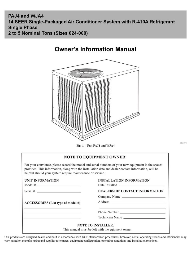
Fig. 2--50GS030-042 and 50GX030-036 Unit Dimensions
COMPRESDORBIOWER,E_ECTRIC_EAT_
& _[ECIRIC ACCESS \ \\
__\
.................................... 11231
144 22} ........................................_\\
LEFT SIDE VIEW
TOP VIEW
40, 0
fl983}
C01L I ...........
_137
[4 €3]
88 3
[348]
DIMENSIONS IN [1 ARE IN !NCHES
SUPPLY "
DUCT
3 3 52 --,-43_1 _ 4
113 831 [3 67] { 3 83
REAR VIEW
445 [!75] OIA KO
POW#R INTRY
22 ' [088] OlA HOLE-
CONTROL ENTRY
8?1
13 43]
1222
[4 81]
__A ,,
_%
'4 I I I
[ODO}
RIGHT SIDE VIEW
REQUIRED CLEARANCE TO COMBUSTIBLE MATE INCHES [ram]
TOP OF UNIT ................................................................................... 14.00 [355.6]
DUCT SIDE OF UNIT ......................................................................... 2.00 [50.8]
SIDE OPPOSITE DUCTS ................................................................ 14.00 [355.6]
BOTI-OM OF UNIT ............................................................................. 0.50 [12.7]
ELECTRIC HEAT PANEL ................................................................. 36.00 [914.4]
NEC. REQUIRED CLEARANCES. INCHES [ram]
BETWEEN UNITS, POWER ENTRY SIDE .................................... 42.00 [1066.8]
UNIT AND UNGROUNDED SURFACES, POWER ENTRY SIDE .38.00 [914.0]
UNIT AND BLOCK OR CONCRETE WALLS AND OTHER
GROUNDED SURFACES, POWER ENTRY SIDE ......................... 42.00 [1086.8]
REQUIRED CLEARANCE FOR OPERATION AND SERVICING INCHES [ram]
EVAR COIL ACCESS SIDE ............................................................ 36.00 [914.0]
POWER ENTRY SIDE .................................................................... 36.00 [914.0]
(EXCEPT FOR NEC REQUIREMENTS)
UNIT TOP ....................................................................................... 48.00 [1219.2]
SIDE OPPOSITE DUCTS .............................................................. 36.00 [914.0]
DUCT PANEL ................................................................................. 12.00 [304.8] *
*MINIMUM DISTANCES: IF UNIT IS PLACED LESS THAN 304.8 [12.00] FROM
WALL SYSTEM, THEN SYSTEM PERFORMANCE MAYBE COMPROMISE.
C99006
UNiT
50GS048
50GS060
50GX042
50GX048
50GX060
ELECTRICAL CHARACTERISTICS
208/230-3-60, 480-3-60
208/230-3-60, 480-3-60
208/230-3-60, 480-3-60
208/230-3-60, 480-3-60
208/230-3-60, 480-3-60
UNIT WEIGHT
lb. kg
324 145
389 178
321 148
328 148
399 181
UNiT HEIGHT
IN. (MM)
"A"
38,98 (990,2)
38,98 (990,2)
38,98 (990,2)
38,98 (990,2)
42,98 (1091,1)
CENTER OF GRAVITY
IN.(MM)
X
20.0 (508.0)
19.0 (482.8)
20.5 (520.7)
19.5 (495.3)
20.5 (520.7)
Y Z
17.0 (432.0) 17.0 (432.0)
18.0 (406.0) 17.0 (432.0)
16.75 (425.5) 16.6 (421.6)
17.8 (447.8) 18.0 (457.2)
18.2 (412.8) 17.6 (447.0)
Fig. 3-- 50GS048-060 and 50GX042-060 Unit Dimensions
b e\ i_i_i_i_i_i_i_!_i!_i_i_i_i_iiiiiiiiiiiiiiiiiiiii_iiiii_iii_iiiiii_iiiiii_iiiiiiiiiiiiiiiiiiiiiiiiii_iiiiiiiii!!!_ilil_iiiii_i!lii!iiiiiiii_illi_il;_.....
/Screw _
/NO- E-Ai
/*Gasketina_ I
___L Wood nailer*
Flashing field ill_l II
II_:iql _4"Insulatio[l(field
Roofingmateial II !i II supp,,ed)
"e'dsupp"ed--1 iIIIt'-Duetwerk
Cant strip IIfield supplied/
Roof Curb for Small Cabinet
Note A:When unit mounting screw is used
retainer bracket must also be used.
Roof Curb for Large Cabinet
Note A:When unit mounting screw is used
retainer bracket must also be used.
Ret_n opening
(BxC)
UNIT SIZE
50GS030-042
50GS048-060
50GX030-036
50GX042-060
NOTES:
1. Dimensions in ( ) are in millimeters.
2. Roof curb is made of 16-gauge steel.
Supplyopening
(BxO)
D
Long
Suppo_
Sho_
Suppo_
R/A
X
\ _ Gasket around _
\ duct
\\
\\\\
\\\\ /_
S/A
/2 \\
Insulated Gasket around
deck pan outer edge \
\,
N
ODS CATALOG NUMBER
CPRFCURB006A00
CPRFCURB007A00
CPRFCURB008A00
CPRFCURB009A00
A
IN.(MM)
8 (203)
14 (356)
8 (203)
14 (356)
B
IN.(MM)
11 (279)
11 (279)
16-3/16 (411)
16-3/16 (411)
C
IN. (MM)
16-1/2 (419)
16-1/2 (419)
17-3/8 (441)
17-3/8 (441)
C00076
D
iN. (MM)
28-3/4 (730)
28-3/4 (730)
40-1/4 (1022)
40-1/4 (1022)
3. Table lists only the dimensions per part number that have changed
4. Insulated panels: 1-in. thick fiberglass 1 lb. density.
Fig. 4A-- Roof Curb Dimensions
1 2
Y
43
C00071
50GS 50GX
CORNER # 030 036 042 048 060 030 036 042 048 060
1 59 62 76 69 84 84 85 71 78 85
2 48 50 50 45 54 60 60 55 56 66
3 56 58 71 88 106 61 64 85 80 108
4 95 98 97 122 145 86 90 110 112 140
TOTAL WEIGHT 258 268 294 324 389 291 299 321 326 399
Fig. 4B--50GS and 50GX Unit Corner Weights
MAXIMUM ALLOWABLE
DIFFERENCE (in.)
A-B B-C A-C
1/4 1/4 1/4
Fig. 5A--Unit Leveling Tolerances
C99065
COND. COIL
Fig. 5B--Slab Mounting Detail
C99096
MINIMUMHEIGHT: 36"
DETAILA
SEEDETAIL A_ f .._EIGHT
MAXIMUM WEIGHT B
SIZE lb. I kg mm. in. I mm.
030 280 127.0 482.6 14 355.6
036 290 131.5 508.0 14 355.6
042 316 143.3 482.6 14 355.6
048 346 156.9 508 17 431.8
060 411 186.4 482.6 18 408.4
030 313 142.5 495.3 15.50 393.7
036 321 145.8 495.3 15.25 387.4
042 343 155.8 520.7 18.75 425.5
048 348 157.9 495.3 17.82 447.6
060 421 191.0 520.7 18.25 412.8
T A
in. I
UNIT 50GS
19
20
19
20
19
UNIT 50GX
19.5
19.5
20.5
19.5
20.5
Fig. 6--Suggested Rigging
A05179
Accessory lifting kit is only to be used with Small Packaged
units which have a composite base pan with molded rigging
holds.
INSPECTION
Prior to initial use, and at monthly intervals, all rigging brackets
and straps should be visually inspected lbr any damage, evidence
of wear, structural delimnation, or cracks. Particular attention
should be paid to excessive wear at hoist hooking points and load
supporl areas. Brackets or straps showing any kind of wear in these
areas must not be used and should be discarded.
INSTALLATION
1. Position the lifting bracket assembly around the base of the
unit. Leave the top shipping skid on the unit to act as a
spreader bar. Be sure the strap does not twist.
2. Place each of the four (4) metal lifting brackets into the
rigging holds in the composite pan.
3. Tighten the ratchet strap unit tight. Lilting brackets should be
secure in the rigging holds.
4. Attach the clevis or book of sull'icient strength to hole in the
lifting bracket (See Fig. 6).
5. Attach safety straps directly to the field supplied rigging straps
or clevis clip. Do not attach the salbty straps to the lifting
brackets.
6. Use the top of the unit as a spreader bar to prevent the rigging
straps li"omdamaging the unit. B'the wood top is not available,
use a spreader bar of suflicient length to not damage the unit.
!
Lilting point should be directly over the center of gravity liar |
the unit. J
Step 6--Connect Condensate Drain
NOTE: When installing condensate drain connection be sure to
comply with local codes and restrictions.
Models 5(tGS and 5(tGX dispose of condensate water through a
3/4 in. NPT fitting which exits through the base on the evaporator
coil access side. See Fig. 2 & 3 liar location.
Condensate water can be drained directly onto the roof in rooliop
installations (where permitted) or onto a gravel apron in ground-
level installations, lnstall a field-supplied condensate trap at end of
condensate connection to ensure proper drainage. Make sure that
the outlet of the trap is at least 1 in. lower than the drainpan
Table 1--Physical Data--Unit 50GS
UNiT SiZE
NOMINAL CAPACITY (ton)
OPERATING WEIGHT (lb.)
COMPRESSOR
REFRIGERANT {R-22)
Quantity {lb.)
REFRIGERANT METERING DEVICE
Orifice ID (in.)
CONDENSER COiL
Rows...Fins/in.
Face Area (sq. ft.)
CONDENSER FAN
Nominal Cfm
Diameter
Motor Hp (Rpm)
EVAPORATOR COIL
Rows...Fins/in.
Face Area (sq. ft.)
EVAPORATOR BLOWER
Nominal Airflow (elm)
Size (in.)
Motor HP (RPM)
RETURN-AIR FILTERS (in.)*
Throwaway
030 036 042 048 060
2-1/2 3 3-1/2 4 5
256 268 294 324 369
Reciprocating Scroll Reciprocating
3.65 4.4 6.4 5.1 7.4
AccuRater®
.034
1...17
9.1
.034 .032 .032 .030
1...17 1...17 1...17 2...17
9.1 10.9 12.3 12.3
2400 3000 3000 3600 3600
22 18 22 22 22
1/8 (825) 1/4 (1100) 1/4 (1100) 1/4 (1100) 1/4 (1100)
2...15 3...15 4...15 3...15 4...15
3.7 3.06 3.06 4.7 4.7
1000 1200 1400 1600 2000
10x10 1lx10 1lx10 1lx10 1lx10
1/4 (1075) 1/2 (1075) 3/4 (1075) 3/4 (1075) 1.0 (1100)
20x20 20x24 20x24 24x30 24x30
* Required filter sizes shown are based on the larger of the ARI (Air Conditioning and Refrigeration Institute) rated cooling airflow or the heating airflow velocity of 300
ft./rnin, for throwaway type or 450 ft./rnin, for high-capacity type. Air filter pressure drop for non-standard filters must not exceed 0.08 in. wg.
condensate connection to prevent the pan from overflowing (See
Fig. 7). When using a gravel apron, make sure it slopes away li"om
tile unit.
Connect a drain tube using a minimum of 3/4 -in. PVC or 314 -in.
copper pipe (all field-supplied) at the outlet end of the 2-in. trap.
Do not undersize the robe. Pitch the drain tube downward at a
slope of at least 1-in. li}r every 10 ft. of horizontal run. Be sure to
check the drain tube %r leaks. Prime trap at the beginning of the
cooling season start-up.
Step 7--install Duct Connections
The unit has duct flanges on the supply- and return-air openings on
the side and bottom of the unit. For downshot applications the
ductwork can be connected to the roof curb. See Fig. 2 & 3 %r
connection sizes and locations.
IMPORTANT: Use flexible connectors between ductwork and
unit to prevent transmission of vibration. Use suitable gaskets to
ensure weatbertight and airtight seal. When electric heat is
installed, use fire proof canvas (or similar heat resistant material)
connector between ductwork and unit discharge connection. If
flexible duct is used, insert a sheet metal sleeve inside duct. Heal
resistant duct connector (or sheet metal sleeve) must extend 24-in.
li"om the unit discharge connection flange into the ductwork.
CONFIGURING UNITS FOR DOWNFLOW (VERTICAL) DIS-
CHARGE
Belbre perlorming service or maintenance operations on the
system, turn off main power to unit and install lockout tag or
electrical shock could result.
1. ()pen all electrical disconnects and install lockout tag belk}re
starting any service work.
2. Remove return duct cover located on duct panel by breaking
lonr (4) connecting tabs with screwdriver and a hammer. (Fig.
sag)
3. To remove supply duct cover, break f_'ont and 1Tightside
connecting tabs with a screwdriver and a hammer. Push louver
down to break rear and left side tabs. (Fig. 8 & 9)
4. If unit ductwork is to be attached to verflcal opening flanges
on the unit composite base (jaekstand applications only), do so
at this time. Collect ALL screws that were removed. Do not
leave screws on rooftop as pemmnent damage to the roof may
OCCUr.
5. It is recommended that the unit base insuhttion around the
perimeter of the vertical return-air opening be secured to the
unit base with aluminum tape. Applicable local codes muy
require aluminum tape to prevent exposed fiberglass.
6. Cover both horizontal duct openings with the duct covers froll]
the accessory duct cover kit. Ensure opening is air-and
watertight.
7. After completing unit conversion, perlorm all salL'ty checks
and power up unit.
NOTE: The design and installation of the duct system must be in
accordance with the standards of the NFPA lbr installation of
nonresidence-type air eondifioning and ventilating systems, NFPA
90A or residence-type, NFPA 90B; and/or local codes and
ordinances.
Adhere to the fl)llowing criteria when selecting, sizing, and
installing the duct system:
8. Units am shipped lot side shot installation.
9. Select and size ductwork, supply-air registers, and return-air
grilles according to American Society of Heating, Refrigera-
tion and Air Conditioning Engineers (ASHRAE) recommen-
dations.
10. Use flexible transition between rigid ductwork and unit to
prevent transndssion of vibration. The transition may be
screwed or bolted to duct flanges. Use suitable gaskets to
ensure weathertight and airtight seal.
11. All units nmst have field-supplied filters or accessory filter
rack installed ilkthe return-air side of the unit. Recommended
sizes lot filters are shown ilk Tables 1 and 2.
TabJe 2--PhysicaJ Data--Unit 50GX
030 036 042
2-1/2 3 3-1/2
291 299 321
Scroll
4.415.217.6 AccuRater®
.034
UNIT SIZE 048 060
NOMINAL CAPACITY (ton) 4 5
OPERATING WEIGHT (lb.) 326 399
COMPRESSOR
REFR,GERANT (R-22) [ 1Quantity (lb.) 8.3 8.1
REFRIGERANT METERING DEVICE
Orifice ID (in.) .030 .032 .034 .032
CONDENSER COIL 1...17 2...17 2...17 2...17 2...17
Rows...Fins/in. 12.7 9.1 9.1 12.3 16.4
Face Area (sq. ft.)
CONDENSER FAN 2350 2350 3300 3300 3300
Nominal Cfm 22 22 22 22 22
Diameter (in.) 1/8 (825) 1/8 (825) 1/4 (1100) 1/4 (1100) 1/4 (1100)
Motor Hp (Rpm)
EVAPORATOR COIL 3...18 3...15 3...15 4...15 4...15
Rows...Fins/in. 3.1 3.7 4.7 4.7 4.7
Face Area (sq. ft.)
EVAPORATOR BLOWER 1000 1200 1400 1600 1750
Nominal Airflow (Cfm) 10x10 1lx10 1lx10 1lx10 1lx10
Size (in.)
Motor Hp (RPM) 1/4 (1075) 1/2 (1075) 3/4 (1075) 3/4 (1075) 1.0 (1040)
RETURN-AIR FILTERS (in,)* 20x20 20x24 20x30 24x30 24x30
Throwaway
Required filter sizes shown are based on the larger of the ARI (Air Conditioning and Refrigeration Institute) rated cooling airflow or the heating airflow velocity of 300
ft./min, for throwaway type or 450 ft./rain, for high-capacity type. Air filter pressure drop for non-standard filters must not exceed 0.08 in. wg.
1" (25mm) MIN. TRAP
OUTLET _
1
2" (50ram) MIN.
Fig. 7--Condensate Trap
Table 3--Minimum Airflow for Safe Electric Heater
Operation (Cfm)
SIZE 030 036 042 048 060
CFM 1000 1200 1400 1600 2000
C99013
12. Size all ductwork lk_r maximum required airflow (either
healing or cooling) lk_runit being installed. Avoid abrupt duct
size increases or decreases or perlormance may be afl_.:cted.
13. Adequately insulate and weatherproof all ductwork located
outdoors. Insulate ducts passing through unconditioned space,
and use vapor barrier in accordance with la_est issue of Sheet
Metal and Air Conditioning Contractors National Association
(SMACNA) and Air Conditioning Contractors of America
(ACCA) ndnimum installation standards lot heating and air
conditioning systems. Secure all ducts to building structure.
14. Flash, weatherproof, and vibration-isolate all openings in
building structure in accordance with local codes and good
building practices.
Step 8--Install Electrical Connection
The unit cabinet must have an uninterrupted, unbroken
electrical ground to minimize the possibility of personal
in,iury if an electrical fault should occur. This ground may
consist of an electrical wire connected to the unit ground lug
in the control compartment, or conduit approved l_r electrical
ground when installed in accordance with NEC (National
Electrical Code) ANSI/NFPA (latest edition) and local elec-
trical codes. In Canada, lollow Canadian Electrical Code
CSA (Canadian Standards Association) C22.1 and local
electrical codes. Failure to adhere to this warning could result
in personal injury or death.
j
j/
SUPPLY
DUCT
OPENING
RETURN
DUCT
OPENING C99011
Fig. 8--Supply and Return Duct Opening
DUCT COVERS REMOVED
C99012
Fig. 9--Vertical Duct Cover Removed
Failure to lbllow these precautions could result in damage to
the unit being installed:
1. Make all electrical connections in accordance with NEC
ANSI/NFPA (latest edition) and local electrical codes
governing such wiring. In Canada, all electrical connec-
tions must be in accordance with CSA standard C22.1
Canadian Electrical Code Part 1 and applicable local
codes. Reli:r to unit wiring diagram.
2. Use only copper conductor lor connections between
field-supplied electrical disconnect switch and unit. DO
NOT USE ALUMINUM WIRE.
3. Be sure that high-voltage power to unit is within operating
voltage range indicated on unit rating plate.
4. Do not damage internal components when drilling through
any panel to mount electrical hardware, conduiL etc. On all
3-phase units, ensure phases are balanced within 2 percent.
Consult local power company lk_rcorrection of improper
voltage and/or phase imbalance.
HIGH-VOLTAGE CONNECTIONS
The unit nmst have a separate electrical service with a field-
supplied, waterproof, disconnect switch mounled at, or within
sight li"om_the unit. RelL'r to the unit rating plate %r maximmn
fuse/circuit breaker size and minimnm circuit amps (ampacity) lor
wire sizing. See Tables 4 and 5 lor electrical data.
The field-supplied disconnect switch box may be mounted on the
unit over the high-voltage inlet hole when the standard power and
low-voltage entry points are used. See Fig. 2 & 3 lor acceptable
location.
See unit wiring label and Fig. 10 %r reli:rence when making high
voltage connections. Proceed as lbllows to complete the high-
voltage connections to the unit.
1. Run the high-voltage (L1, L2, L3) and ground leads into the
control box.
2. Connect ground lead to chassis ground connection.
3. Locate the black and yellow wires connected to the lines side
of the contactor.
4. Connect lield L1 to black wire on connection 11 of the
c{}mpressor cnnt actor.
5. Connect field wire L2 to yellow wire on connection 13 of the
compressor contactor.
6. Connect field wire L3 to Blue wire fl'om compressor.
SPECIAL PROCEDURES FOR 208-V OPERATION
Make sure that the power supply to the unit is switched OFF
and lockout tag installed belore making any wiring changes.
Electrical shock can cause serious injury or death.
10
C()NTR(-)L VOLTAGE CONNECTIONS
NOTE: Do not use any type of power-stealing thermostat. Unit
control problems may result.
Use no. 18 American Wire Gage (AWG) color-code& insulated
(35°C miuinmm) wires to make the control voltage connections
between the thermostat and the unit. If the thermostat is located
more than l(t0 ft. fl'on_ the unit (as measured along the control
voltage wires), use no. 16 AWG color-coded, insulated (35 ° C
ndnimum) wires.
Table 4--ElectricM Data--5OGS
UNiT 50GS
SIZE
030
038
042
048
060
V-PH-HZ
208/230-3-60
208/230-3-60
460-3-60
208/230-3-60
460-3-60
208/230-3-60
460-3-60
208/230-3-60
460-3-60
VOLTAGE
RANGE
Min Max
187 254
187 254
414 508
187 254
414 508
187 254
414 508
187 254
414 508
COMPRESSOR OFM IFM
RLA LRA FLA FLA
8.3 68 0.8 2
10.9 78 1.4 2.8
5.8 40 0.8 1.4
10.7 85 1.4 4
5.3 42 0.8 2
14.6 108 2.1 5
7.3 48 1.1 2.3
18.6 125 2.1 6.8
8.5 66.5 1.1 3.2
ELECTRIC HEAT
Nominal kW* FLA
-/- -/-
3.8/5.0 10.4/12.0
7.5/10.0 20.8/24.1
11.3/15.0 31.3/36.1
-/- -/-
3.8/5.0 10.4/12.0
7.5/10.0 20.8/24.1
11.3/15.0 31.3/36.1
5 6
10 12
15 18
-/- 10.4/12.0
3.8/5.0 20.8/24.1
7.5/10.0 31.3/36.1
11.3/15.0 41.6/48.0
15.0/19.9
5 6
10 12
15 18
20 24.1
-/- -/-
3.8/5.0 10.4/12.0
7.5/10.0 20.8/24.1
11.3/15.0 31.3/36.1
15.0/19.9 41.6/48.0
5 6
10 12
15 18
20 24.1
-/- -/-
3.8/5.0 10.4/12.0
7.5/10.0 20.8/24.1
11.3/15.0 31.3/36.1
15.0/19.9 41.6/48.0
5 6
10 12
15 18
20 24
POWER SUPPLY
MCA Max Fuse orCkt Bkr
13.2/13.2 20/20
15.5/17.5 20/20
28.6/32.6 30/35
41.6/47.6 45/50
17.8/17.8 25/25
16.5/18.5 25/25
29.6/33.6 30/35
42.6/48.6 45/50
9.5 15
9.5 15
16.8 20
24.3 25
25/25
18.8/18.8 25/25
31.1/35.1 35/40
44.1/50.1 45/60
57.0/65.0
9.4 15
10.0 15
17.5 20
25.1 30
32.6 35
25.4/25.4 30/30
25.4/25.4 30/30
32.3/36.3 35/40
45.3/51.4 50/60
58.2/66.2
12.5 15
12.5 15
17.9 20
25.4 30
32.9 35
32.2/32.2 40/40
32.2/32.2 40/40
34.6/38.6 40/40
47.6/53.6 50/60
60.5/68.5
14.9 20
14.9 20
19.0 20
26.6 30
34.1 35
MOCP
60/70
60/70
70/70
(See legend following Electrical Data charts)
STANDARD CONNECTION
Remove knockout hole located in the electric heat panel adjacem
to the control access panel. See Fig. g& 3. Remove the rubber
grommet l_'om the installer's packet (included with unit) and install
grommet in the knockout opening. Provide a drip loop belbre
running wire through panel.
Run the low-voltage leads l}'om the thermostat, through the inlet
hole, and into unit low-voltage splice box.
Locate five 18-gauge wires leaving control box. These low-voltage
connection leads can be identified by the colors red, green, yellow,
brown, and white (See Fig. 10). Ensure the leads are long enough
to be routed into the low-voltage splice box (located below right
side of control box). Stripped yellow wire is located in connection
box. Route leads through hole in bottom of control box and make
low-voltage connections (See Fig. 10). Secure all cut wires, so that
they do not interli:re with operation of unit.
TRANSFORMER PROTECTION
The tran._fbrtnur is ol' the energy-limiting type. It is set to
withstand a 30-second overload or shorted secondary condition.
P
HIGH VOLTAGE |
POWER LEADS <o=
(SEE UNITWIRINGI
LABEL) [?=
CONTROLBOX
LOW-VO LTAG E
POWER LEADS-
(SEE UNIT
WIRING LABEL)
m
m = =_o.E f.
,[--
GND
SPLICE BOX
LEGEND
Field Control-Voltage Wiring
Field High-Voltage Wiring
: _LPOWER
.... '_ _ = 4jSUPPLY
FIELD-SUPPLIED
FUSED DISCONNECT
YE==Lff).=,D,=@THERMOSTAT
-GRN(G2 _ @|(TYPICAL)
REUaj.O" @J
BRN(._C! ,,_ @
C99010rev2
Fig. 10--High- and Control-Voltage Connections
II
Table 5--ElectricaJ Data--50GX
UNiT 50GX
SIZE
030
036
042
048
060
V-PH-HZ
208/230-3-60
208/230-3-80
460-3-80
208/230-3-80
460-3-80
208/230-3-60
460-3-80
208/230-3-60
460-3-80
VOLTAGE
RANGE
Min Max
187 253
187 253
414 506
187 253
414 506
187 253
414 506
187 253
414 506
COMPRESSOR OFM
RLA LRA FLA
9.0 83.0 0.8
11.2 75.0 0.8
5.4 37.5 0.9
12.4 88.0 1.6
8.1 44.0 0.9
13.0 93.0 1.5
6.4 46.5 0.9
17.3 123.0 1.6
9.0 62.0 0.9
IFM ELECTRIC HEAT
FLA Nominal Kw* FLA
-/- -/-
3.8/5.0 10.4/12.0
2.1 7.5/10.0 20.8/24.1
11.3/15.0 31.3/38.1
-/- -/-
3.8/5.0 10.4/12.0
3.8 7.5/10.0 20.8/24.1
11.3/15.0 31.3/38.1
-/-
5 6
1.9 10 12
15 18
-/- -/-
3.8/5.0 10.4/12.0
4.1 7.5/10.0 20.8/24.1
11.3/15.0 31.3/38.1
15.0/20.0 41.7/48.1
-/-
5 6.0
2.0 10 12.0
15 18.0
20 24.1
-/- -/-
3.8/5.0 10.4/12.0
4.1 7.5/10.0 20.8/24.1
11.3/15.0 31.3/36.1
15.0/20.0 41.7/48.1
-/-
5 6.0
1.9 10 12.0
15 18.0
20 24.1
-/- -/-
3.8/5.0 10.4/12.0
6.2 7.5/10.0 20.8/24.1
11.3/15.0 31.3/36.1
15.0/20.0 41.7/48.1
-/-
5 6.0
3.2 10 12.0
15 18.0
20 24.1
POWER SUPPLY
Max Fuse
MCA or
Ckt Bkr
14.2/14.2 20/20
15.7/17.7 20/20
28.7/32.7 30/35
41.7/47.7 45/50
18.4/18.4 25/25
18.4/19.5 25/25
30.6/34.8 35/35
43.6/49.6 45/50
9.6 15
9.8 15
17.4 20
24.9 25
21.2/21.2 25/25
21.2/21.2 25/25
31.2/35.2 35/40
44.2/50.2 45/60
57.2/65.3
10.5 15
10.5 15
17.5 20
25.1 30
32.6 35
21.9/21.9 30/30
21.9/21.9 30/30
31.2/35.2 35/40
44.2/50.2 45/60
57.2/65.3
10.8 15
10.8 15
17.4 20
24.9 25
32.4 35
29.4/29.4 35/35
29.4/29.4 35/35
33.8/37.8 35/40
46.8/52.9 50/60
59.9/67.9
15.4 20
15.4 20
19.0 20
26.6 30
34.1 35
(See legend following Electrical Data charts)
MOCP
60/70
60/70
60/70
LEGEND @
FLA -- Full Load Amps
LRA -- Locked RotorAmps CUS
MCA -- Minimum Circuit Amps
MOCP -- Maximum Overcurrent Protection
RLA -- Rated Load Amps
CKT BKR -- Circuit Breaker
NOTES:
1. In compliance with NEC (National Electrical Code) requirements
for multimotor and combination load equipment (refer to NEC
Articles 430 and 440), the overcurrent protective device for the
unit shall be Power Supply fuse. Canadian units may be
fuse or circuit breaker.
2. Minimum wire size is based on 60 C copper wire. If other than
60 C wire is used, or if length exceeds wire length in table,
determine size from NEC.
3. Unbalanced 3-Phase Supply Voltage
Never operate a motor where a phase imbalance in supply volt-
age is greater than 2%. Use the following formula to determine
the percentage of voltage imbalance.
% Voltage imbalance
= 100 x max voltage deviation from average voltage
average voltage
EXAMPLE: Supply voltage is 460-3-60.
A B C AB = 452 v
BC = 464 v
AC = 455 v
Average Voltage = 452+ 464+ 455
3
1371
3
= 457
Determine maximum deviation from average voltage.
(AB) 457 452=5v
(B0) 464 457=7v
(AC) 457 456=2v
Maximum deviation is 7 v.
Determine percent of voltage imbalance.
7
% Voltage Imbalance = 100 x --
457
= 1.53%
This amount of phase imbalance is satisfactory as it is below the
maximum allowable 2%.
IMPORTANT: If the supply voltage phase imbalance is
more than 2%, contact your local electric utility company
immediately.
12
PRE-START-UP
=t , +
Failure to observe the lollowing warnings could result in
serious personal injury:
1. Follow recognized saikXy practices and wear protective
goggles when checking or servicing re[bigerant system.
2. Do not operate compressor or provide any electric power to
unit unless compressor terminal cover is in place and
secured.
3. Do not remove compressor terminal cover until all electri-
cal sources are disconnected.
4. Relieve and recover all refrigerant fl'om system belbre
touching or disturbing anything inside terminal box if
refrigerant leak is suspected around compressor terminals.
5. Never attempt to repair soldered connection while refrig-
erant system is under pressure.
6. Do not use torch to remove any component. System
contains oil and refrigerant under pressure. To remove a
component, wear protective goggles and proceed as lbl-
lows:
a. Shut olT electrical power to unit.
b. Relieve and reclaim all refrigerant l_'om system using
both high- and low-pressure ports.
e. Cut component connecting tubing with tubing cutter and
remove component l_'om unit.
d. Carefully unsweat remaining tubing stubs when neces-
saU. Oil can ignite when exposed to torch flame.
Proceed as lk>llows to inspect and prepare the unit lk)r initial
starmp:
1. Remove access panel.
2. Read and flfllow instructions on all WARNING, CAUTION,
and INFORMATION labels attached to, or shipped with, unit.
3. Make the lollowing inspections:
a. Inspect lk)r shipping and handling damages such as broken
lines, loose parts, disconnected wires, etc.
b. Inspect lot oil at all refrigerant tubing connections and on
unit base. Detecting oil generally indicates a refrigerant
leak. Leak test all refrigerant tubing connections using
electronic leak detector, halide torch, or liquid-soap solu-
tion. If a refrigerant leak is detected, see Check fl_r
Refrigerant Leaks section.
e. Inspect all field- and factory-wiring connections. Be sum
that connections are completed and tight.
d. Ensure electrical wiring does not contact refi+igerant tubes
or sharp metal edges.
e. Inspect coil lins. If damaged during shipping and handling,
carefully straighten fins with a l]n comb.
Verily the fifth>wing conditions:
a. Make sure that condenser-fan blade is correctly positioned
in fan orifice. Leading edge of condenser-Rm blade should
be 1/2 in. maximum from fan orifice (See Fig. 11).
b. Make sure that air lilter(s) is in place.
e. Make sure that condensate drain trap is filled with water to
ensure proper drainage.
d. Make sure that all tools and miscellaneous loose parts have
been removed.
START-UP
CHECK FOR REFRIGERANT LEAKS
Proceed as lk)llows to locate and repair a refrigerant leak and to
charge the unit:
13
1. Locate leak and make sure that rel]'igerant system pressure has
been relieved and reclaimed from both high- and low-pressure
ports.
MOTOR _ I I FAN GRILLE
MOTOR AND FAN HUB MOTOR SHAFT C99009
Fig. 11--Fan Blade Clearance
2. Repair leak fl>llowing accepted practices. NOTE: Install a
filter drier whenever the system has been opened lk)r repair.
3. Add a small charge of R-22 refi'igerant vapor to system and
leak-test unit.
4. Recover refrigerant [bom refrigerant system and evacuate to
500 microns if no additional leaks are not fimnd.
5. Charge unit with R-22 m[_'igerant, using a volumetric-
charging cylinder or accurate scale. R_ifi,r to refit rating plaR,
.fi)r rg,quirg,d charge. Be sure to add extra refl'igerant to
compensate lor internal volume of filter drier.
START UP COOLING SECTION AND MAKE ADJUST-
MENTS
Complete the required procedures given in the Pre-Start- Up
section befl)re starting the unit. Do not jumper any salety
devices when operating the unit. Do not operate the compres-
sor when the outdoor temperature is below 40°F (unless
accessory low-ambient kit is installed). Do not rapid-cycle the
compressor. Allow 5 minutes between "on" cycles to prevent
compressor damage.
CHECKING COOLING CONTROL OPERATION
Start and check the unit lk)r proper cooling control operation as
flfllows:
1. Place room them]ostat SYSTEM switch in OFF position.
Observe that blower motor statls when FAN switch is placed
in ON position and shuts down after 30 second lan time delay
expires when FAN switch is placed in AUTO position.
2. Place SYSTEM switch in COOL position and FAN switch in
AUTO position. Set cooling control below rot>]]]temperature.
Observe that compressor+ condenser fan, and evaporator
blower motors start. Observe that compressor and outdoor fan
shut down when control setting is satislied and that indoor
blower shuts down alter 30 second fan time delay expires.
3. When using an auto-changeover rot>]]]them]ostat, place both
SYSTEM and FAN switches in AUTO positions. Observe that
unit operates in beating mode when temperature control is set
to "call fl_rheating" (above room temperature) and operates in
cooling mode when temperature control is set to "call lk)r
cooling" (below room temperature).
IMPORTANT: Three-phase, scroll compressor units (50GS048,
50GX030-060) are direction-oriented. These units must be
checked to ensure proper compressor 3-phase power lead orienta-
tion. If' not corrected within 5 minutes, the internal protector will
shut off the compressor. The 3-phase power leads to the unit nmst
be reversed to correct rotation. When turning backwards, scroll
compressors emit elevated noise levels, and the dil]i:mnce between
compressor suction and discharge pressures may be dramatically
lower than normal.
CHECKING AND ADJUSTING REFRIGERANT CHARGE
The refrigerant system is fully charged with R-22 refrigerant,
tested, and factory-sealed.
NOTE: Adjtlstment of the refrigerant charge is not required
unless the unit is suspected of not having the proper R-22 charge.
A superheat charging chart is attached to the outside of the service
access panel. The chart includes the required suction line tempera-
ture at given suction line pressures and outdoor ambient tempera-
tures (See Fig. 14 23).
An accurate superheat, tbermocouple- or thermistor-type ther-
mometer, a sling psychrometer, and a gauge manilk_ld are required
when using the superheat charging n_ethod liar evaluating the unit
charge. Do not u_semer_110 or _snlall dial-OT)e thermometer,_
because they are not adequaW.fi_r this 07_e q[ measurement.
NOTE: Allow system to operate in the cooling mode li_}ra
minimmn of 10 minutes beR_re checking or adjusting refrigerant
charge.
I.0
When evaluating the refrigerant charge, an indicated adjust-
ment to the specified lactory charge must always be very
mininml, lf a substantial adjustment is indicated, an abnormal
condition exists somewhere in the cooling system, such as
insufficient airflow across either coil or both coils.
Proceed as lifllows:
1. Remove caps li"om low- and high-pressure service fittings.
2. Using hoses with valve core depressors, attach low- and
high-pressure gauge hoses to low- and high-pressure service
fittings, respectively.
3. Start unit in Cooling mode and let unit run until system
pressures stabilize.
4. Measure and record the li_llowing:
a. Outdoor ambient-air temperature (°F db).
b. Evaporator inlet-air temperature (°F wb).
c. Suction-tube temperature (°F) at low-side service fitting.
d. Suction (low-side) pressure (psig).
5. Using "Cooling Charging Charts" compare outdoor-air ten>
perature (°F db) with the suction line pressure (psig) to
determine desired system operating suction line temperature.
See Fig. 14-23.
6. Compare actual suction-robe temperature with desired
suction-robe temperature. Using a tolerance of +_3°F, add
rcli"igerant if actual temperature is more than 3°F higher than
proper suction-robe temperature, or remove refrigerant if
actual temperature is more than 3°F lower than required
suction-tube temperature.
NOTE: If the problem causing the inaccurate readings is a
refrigerant leak, relier to Check lot Refrigerant Leaks section.
INDOOR AIRFLOW AND AIRFLOW ADJUSTMENTS
For cooling operation, lhe recommended airflow is 350 to 450 |
/
clSn liar each 12,000 Btuh o[ raled cooling capacily. J
Tables 8 and 9 show cooling airflows at various external static
pressures. Reler to these tables to determine the airflow lot the
system being installed.
NOTE: Be sure that all supply- and return-air grilles are open,
free li"om obstructions, and at[justed properly.
Disconnect electrical power to the unit and install lockout tag
belk)re changing blower speed. Electrical shock can cause
serious injury or death.
Airflow can be changed by changing the lead connections of the
blower motor.
Unit 50GS two- or throe-speed motors (except size 030) are
factory wired liar low speed operation. Unit 50GS030 is lactory
wired lot medium speed.
All 50GX units are factory wired liar low speed and may need to
be wired liar medium or high speed in the field.
FOR 2081230V
For color coding on the 208/230V motor leads, see Table 6.
Table 6--Color Coding for 208/230-V Motor Leads
3-SPEED 2-SPEED
black = high speed black = high speed
blue = medium speed
red = low speed red= low speed
To change the speed of the indoor fan motor (IFM), remove the fan
motor speed leg lead li"om the time delay relay (TDR). This wire
is attached to terndnal 3 of TDR liar 3-phase units. To change the
speed, remove and replace with lead liar desired blower motor
speed. Insulate the removed lead to avoid contact n'ith chassis
parts.
FOR 460-V GE MOTORS
For color coding on the 460-v GE motor leads, see Table 7.
Table 7--Color Coding for 460-V GE Motor Leads
3-SPEED 2-SPEED
black = high black = high
violet = jumper blue = jumper
orange = medium
red = low red = low
14
To change the speed of the indoor fan motor (IFM), remove fan
motor speed lead li"om the time delay relay (TDR) and replace with
the lead lot the desired blower motor speed. The motor speed lead
is attached to terndnal 3 of TDR. For low and medium speeds
black must be connected to the jumper wire. lnsMate remoled lead
end to m,oM contact n'ith chassis parts. To select high speed on
460-v GE motors, separate the black lemale quick connect (QC)
from the jumper lead male quick connect (QC) and connect the
black lead to the BR. Insulate the jumper to cn,oM contact l_ith any
cha,s,sispart,s.
COOLING SEQUENCE OF OPERATION
With the room thermostat SYSTEM switch in the COOL position
and the FAN switch in the AUTO position, the cooling sequence
of operation is as 12>llows:
When the room temperature rises to a point that is slightly above
the cooling control setting of the thern_ostat, the thermostat
completes the circuit between thermostat terminal R to terminals Y
and G. These completed circuits through the thermostat connect
contactor coil (C) (through unit wire Y) and time delay relay
(TDR) (through unit wire G) across the 24-v secondary of
translormer (TRAN).
OFM
HEAT SCHEMATIC i i
I I
COMP
IFM
I
ON 6
FAN
THI
W2
SEE NOTE#R
COMMON
m
I
I
T
WII BRN
WI21 RED
WI6 GRN
Wl13 YEL
W72 WHT
WI63 PNK
W162 VIO
WI66 GRA--
Wl53 BRN
W127 BRN
Wll BRN
WlO BRN
ACCESSORY ELECTRIC HEAT_ _WIO BRN
__)_W wTO BRN153 BRN
HRI (5 KW) BRN
HRI &2(IO KW)
WgO BRN
HRI,2 & 3 (15 KW)_I_W59 BRNBRN
HRI,2,3 & 4 {20 KW)
W127 BRN
24V SPLICE BOX
UNIT COMPONENT ARRANGEMENT
OUTDOORFAN []_[_[[[[_
SECTION
COMPRESSORINDOORFAN
SECTION SECTION
COMP
c s
R
50GNO42060
50GS048&/060
CONTROLBOXAREA
F-_
SINGLEPT |
CONNECTION
FOR
ELECTHEAT
SEEHEATER
SCHEMATIC
FORWIRING
[24BVoxSPLICE-
-EQUIP
GND
= DISCONNECT
-- -_-_PER NEC
24V POWER ENTRY
LEGEND
FIELD SPLICE C CONTACTOR
<D TERMINAL (MARKED) CAP CAPACITOR
o TERMINAL (UNMARKED) COMP COMPRESSOR MOTOR
o SPLICE EQUIP EQUIPMENT
(_SPLICE (MARKED) GND GROUND
FACTORY WIRING HR HEATER RELAY
FIELD CONTROL WIRING IFM INDOOR FAN MOTOR
--- FIELD POWER WIRING IP INTERNAL PROTECTOR
--- ACCESSORY OR OPTIONALOFM OUTDOOR FAN MOTOR
WIRING QT QUADRUPLE TERMINAL
--TO INDICATE COMMON TC THERMOSTAT COOLING
POTENTIAL ONLY: TDR TIME DELAY RELAY
NOT TO REPRESENT TH THERMOSTAT HEATING
WIRING TRAN TRANSFORMER
TDR {113) FAN SEQUENCE
0 T %30
G G
ENERGINND DEENERGIZED
NOTES:
IIF ANY OF THE ORIGINAL WIRES FURNISHED ARE REPLACED,
IT MUST BE REPLACED WITH TYPE 90 DEGREE C WIRE OR
IT'S EQUIVALENT
2.SEE PRICE PAGES FOR THERMOSTAT AND SUBBASES
3USE 75 DEGREE COPPER CONDUCTORS FOR FIELD INSTALLATION
41FOR HIGH SPEED IFM,DISCONNECT RED
WIRE FROM TDR;3 AND CONNECT BLK WIRE FROM IFM
FOR MEDIUM SPEED,DISCONNECT RED WIRE
FROM TDR:3 AND CONNECT BLU WIRE FROM IFM
Fig. 12--Wiring Diagram (208/230-3-60)
C99004
15
MAXIMUM WIRE
SIZE 2 AWG.
USED WITH
ACCESSORY
ELECT.HEAT
OPTION ONLY.
USED WITH
HEATER OPTIONS
5,10 & 15 KW
MAXIMUM WIRE
SIZE 2 AWG.
USED WITH
ACCESSORY
ELECTHEAT
OPTION ONLY.
USED WITH
HEATER OPTIONS
20 KW <ONLY)
MAXIMUM WIRE
SIZE 2/D AWG
m FIELD C 018 048 ONLY
m _Wl BLK _(TT'_A_WIS5 BLK _ BLK_
WI46 BLK
.WE w2YEL W4R APR OPM
sUPPLY_ F"_ _--// _W,36YEL __RR_
,__ ,.j _LWIS2 BLU _ _ /L2 QT 660 ONLY
i....... _ LI
, ,_ _ _YEL _ I _ L_ _ _
:,_:::Z ] i _ _ T0R
._ __p__LU_::_E_____ w,_RED_o_
m _ TO W141 YEL_ YEL
_BRN/W'HT_[[[_ _ IFM
I_TO "CAPI[OR YEL \ /
' -- _I WI56 BLK_ QTL__BRN_
i __R_ LW 57 YEL_ PRIMARMARY_
_3DAMP SB i HTR I
m _, __ITO I / //
HTR i
I _3_I _CT j __W25 GRN YEL_W26 GRN YEL_
...... GRN YEL GRN YEL
I_20 KW SHOWN'SEE ELECTRIC HEAT _I • I
SCHEMATIC FOR VARIT IONS, #_'_SECONDARY ®/ ÷ W,, BRN
- q 23ov L
_WI23 ORN
/WIRY BRN
ON G
FAN
AUTO SW
W2
SEE NOTE#R
COMMON
WI21 RED
Z_ Wl6 GRN
WII3 YEL
W7R WHT
IWI63 PNK
WI62 VlO
WI64 GRA
/-
WI55 BRN
WI27 BRN
24V SPLICE BOX
Wll BRN
WlO BRN
ACCESSORY ELECTRIC HEAT_ __,_.jWlO BRN
KW) I _ _W7O BRN
HRI (5 __-'_R_!--_WIS5 BRN
HRI & HR2 (IO KW)_'/_""-/II__8 BRN
HRI,2 & 3 _I _
(ISKW)
W70 BRN
HRI,2,3 & 4 (20 KW)_IH_ 9 BRN
I
UNIT COMPONENT ARRANGEMENT
OUTDOORFAN
SECTION
COMPRESSOR INDOOR FAN
SECTION SECTION
COMP
cs
R
:AP2
50GX042060
50GSO48&?60
CONTROLBOX AREA
SINGLEPT.
CONNECTION
FOR
ELECT,HEAT
SEEHEATER
SCHEMAiICF_/_ _
FORWIRING
LEGEND
z_. FIELD SPLICE CCONTACTOR
TERMINAL <MARKED) CAP CAPACITOR
o TERMINAL <UNMARKED) COMP COMPRESSOR MOTOR
• SPLICE EQUIP EQUIPMENT
SPLICE <MARKED) FU FUSE
FACTORY WIRING GND GROUND
FIELD CONTROL WIRING HR HEATER RELAY
--- FIELD POWER WIRING HTR HEATER
--- ACCESSORY OR OPTIONAL IFM INDOOR FAN MOTOR
IP INTERNAL PROTECTOR
WIRING OFM OUTDOOR FAN MOTOR
--TO INDICATE COMMON
POTENTIAL ONLY: QT QUADRUPLE TERMINAL
NOT TO REPRESENT SB SLOW BLOW FUSE
WIRING TC THERMOSTAT COOLING
TDR TIME DELAY RELAY
TH THERMOSTAT HEATING
TRAN TRANSFORMER
NOTES:
24V POWER ENTRY
liP ANY Of THE ORIGINAL WIRES FURNISHED ARE REPLACED,
IT MUST BE REPLACED WITH TYPE 90 DEGREE C WIRE OR
IT'S EQUIVALENT
R.SEE PRICE PAGES FOR THERMOSTAT AND SUBBASES,
3USE 75 DEGREE COPPER CONDUCTORS FOR FIELD INSTALLATION
4FOR HIGH SPEED IFM,DISCONNECT RED
WIRE FROM TDR;3 AND CONNECT BLK WIRE FROM IFM
FOR MEDIUM SPEED,DISCONNECT RED WIRE
FROM TDR;3 AND CONNECT BLU WIRE FROM IFM
TDR II13) FAN SEQUENCE
0 T T+3O
G 6
ENERGIZED DEENERGIZED
C99005
Fig. 13--Wiring Diagram (460-3-60)
16
TaNe 8--Wet CoiJ Air DeJivery (Deduct 10 percent for 208v)*
HorizontaJ and Downflow Discharge
Unit 50GS030-060
Unit
030
036
042
O48
060
230 AND 460 VOLT
Motor External Static Pressure (in. wg)
Speed 0.0 0.1 0.2 0.3 0.4 0.5 0.8 0.7 0.8
Watts 280 275 270 287 284 262 260
Low Cfm 880 825 765 693 600 450 281
Watts 380 375 365 360 355 350 344 335 312
Med Cfm 1138 1085 1010 946 885 787 850 495 380
Watts 485 475 470 480 455 445 437 430 415 385
High Cfm 1415 1332 1266 1180 1100 1000 900 780 480 256
Watts 470 458 445 430 415 399 384
Low Cfm 1352 1257 1240 1199 1107 1015 924
Watts 514 501 487 471 455 438 422
Med Cfm 1338 1295 1288 1181 1111 968 813
Watts 646 636 626 614 602 589
High Cfm 1385 1268 1196 1159 1032 948
Watts 675 660 650 640 630 620 610 595 580
Low Cfm 1387 1326 1275 1204 1142 1081 995 918 850
Watts 886 855 825 795 778 765 750 735 718
Med Cfm 1458 1406 1350 1285 1224 1163 1091 1013 932
Watts 1000 950 925 910 890 875 855
High Cfm 1488 1424 1360 1296 1233 1148 1071
Watts 727 712 700 688 866 844 622 595 569
Low Cfm 1640 1800 1575 1505 1450 1390 1300 1205 1145
Watts 853 838 821 807 782 756 730 699 867
Med Cfm 1880 1830 1770 1700 1642 1565 1482 1385 1290
Watts 979 959 943 927 897 868 838 802 768
High Cfm 2090 2048 1997 1922 1845 1750 1800 1550 1425
Watts 1033 949 864 836 822 808 772 737 705 874
Low Cfm 2050 2000 1945 1905 1880 1820 1775 1895 1627 1530
Watts 1084 1054 1024 994 971 955 928 897 867 835
Med Cfm 2248 2179 2110 2058 2000 1932 1885 1829 1740 1638
Watts 1184 1152 1120 1102 1084 1058 1029 997
High Cfm 2278 2207 2124 2041 2000 1960 1856 1748
0.9 1.0
70O
87O
833
1005
840
1210
730
1380
842
1480
803
1569
965
1845
* Air delivery values are based on operating voltage of 230v or 460v, wet coil, without filter or electric heater. Deduct filter and electric heater pressure drops to obtain
static pressure available for ducting.
NOTES:
1. Do not operate the unit at a cooling airflow that is less than 350 cfrn for each 12,000 Btuh of rated cooling capacity. Evaporator coil frosting may occur at airflows below
this point.
2. Dashes indicate portions of table that are beyond the blower motor capacity or are not recommended.
The normally open contacts ef energized contactor (C) close and
complete the circuit through compressor motor (COMP) to con-
denser (outdoor) fun motor (OFM). Both motors start instantly.
The set of normally open contacts of energized relay TDR close
and complete the circuit through evaporator blower (indoor) fun
motor (1FM).
NOTE: Once the compressor has started and then has stopped, it
should not be started again until 5 minutes have elapsed.
The cooling cycle remains "on" until the room temperature drops
to a point that is slightly below the cooling control setting of the
room thermostat. At this peint, the thermostat "breaks" the circuit
between thermostat terminal R to terminals Y and G. These open
circuits deenergize contactor coil C and relay coil TDR. The
condenser and compressor motors stop. Alter a 30-second delay,
the blower motor stops. The unit is in a "standby" conditien,
waiting lk_r the next "call lk>r cooling" 15"orethe room thermostat.
MAINTENANCE
To ensure continuing high perlbrmance, and to minimize the
possibility of premature equipment failure, periodic maintenance
nmst be perlbrmed on this equipment. This cooling unit should be
inspected at least once each year by a qualified service person. To
troubleshoot beating or cooling of units, reli:r to tables at the back
of the book.
See Fig. 14 IS lor 50GS Cooling Charging Charts.
See Fig. 19 23 liar 50GX Cooling Charging Charts.
NOTE TO EQUIPMENT OWNER: Constalt your local dealer
about the availability of a maintenance contract.
The ability to properly pel'lkrrul maintenance en this equip-
ment requires certain expertise, mechanical skills, tools, and
equipment. If you do not possess these, do not attempt to
pel'lk}rm any maintenance on this equipment other than those
procedures recommended in the User's Manuah FAILURE
TO HEED THIS WARNING COULD RESULT 1N SERI-
OUS PERSONAL INJURY AND POSSIBLE DAMAGE TO
THIS EQUIPMENT.
17
Table 9--Wet Coil Air Delivery (Deduct 10 percent for 208v)*
Horizontal and Downflow Discharge
Unit 50GX030-060
Unit
030
036
042
048
060
Motor
Speed Watts
Low Cfm
Watts
Med Cfm
Watts
High Cfm
Watts
Low Cfm
Watts
Med Cfm
Watts
High Cfm
Watts
Low Cfm
Watts
Med Cfm
Watts
High Cfm
Watts
Low Cfm
Watts
Med Cfm
Watts
High Cfm
Watts
Low Cfm
Watts
Med Cfm
Watts
High Cfm
0.0 0.1 0.2
246 244 243
910 806 749
343 339 338 332
1148 1104 1028 988
470 458
1352 1257
814
1338
825 814
1540 1510
230 AND 460 VOLT
External Static Pressure (in. wg)
0.3 0.4 0.8 0.8 0.7
241
680 328 322 317
880 782 848
441 432 421 410
1102 988 898 783
448 430 415 399 384
1240 1199 1107 1015 924
501 487 471 455 438
1295 1288 1181 1111 968
648 636 826 814 602
1388 1268 1196 1159 1032
605 593 874 549 518
1473 1398 1348 1288 1192
726 895 861 628
1648 1593 1530 1448
790
0.8 0.9 1.0
4OO
529
422
813
589
948
485 454
1124 1037
591 861
1352 1237
788 7421
888 877
1514 1543
786 738
1785 1785
903 898 873
2190 2158 2081
1002 978
2389 2291
1818 1492 1394
572 586 556 539 517 491
1467 1408 1374 1324 1237 1161
719 699 876 850 623 596 872
1708 1628 1577 1503 1421 1357 1298
896 882 829 800 775 752
1880 1804 1704 1547 1565 1406
842 814 792 777 764 743 701
2028 1958 1866 1822 1744 1678 1535
960 941 914 880 839 798 784
2218 2120 2020 1952 1852 1727 1617
1080 1080 1066 1041 1008 972 938
2318 2181 2122 2101 2000 1802 1672
54O
1114
713
1283
555
1253
728
1367
818
1377
750
1549
* Air delivery values are based on operating voltage of 230v or 460v, wet coil, without filter or electric heater. Deduct filter and electric heater pressure drops to obtain
static pressure available for ducting.
NOTES:
1. Do not operate the unit at a cooling airflow that is less than 350 cfm for each 12,000 Btuh of rated cooling capacity. Evaporator coil frosting may occur at airflows below
this point.
2. Dashes indicate portions of table that are beyond the blower motor capacity or are not recommended.
Failure to lollow these warnings could result in serious
personal injury:
1. Turn o11"electrical power to the unit and install lockout tag
belk}re perlbnning any maintenance or service on the unit.
2. Use extreme caution when removing panels and parts. As
with any mechanical equipment, personal injury can result
l_'om sharp edges, etc.
3. Never place anything combustible either on, or in contact
with, the unit.
18
Errors made when reconnecting wires may cause improper
and dangerous operation. Label all wires prior to disconnec-
tion when servicing.
The minimum maintenance l'equirements fl_rthis equipment are as
lkHlows:
1. Inspect air filter(s) each month. Clean or replace when
necessary.
2. Inspect indoor coil, drain pan, and condensate drain at least
each cooling season lkn"cleanliness. Clean when necessary.
3. Inspect blower motor and wheel lbr cleanliness and check
lubrication each heating and cooling season. Clean when
necessary.
75E 110
68. c 1 O0
521s90IIIII
mus ii iii
o _ II III
855: IIIII
_ IIIII :
_n 45-" I I I I I
_0
w_W lllll
w
z41z zBO
J
oz o
27E 40
3O
OUTOOORTEMF
115 48
105 41
._ 55 13
I 45 7
t _-J l
75E 110 1
68E 100
us 48:_70
zA1z z60
34E mS0
27E 40
3O
30 50 60 70 80 90
LINE TEHPERATURE ('F)
IIIIIII
4 10 16 21 27 32
5UCTION LINE TEHPERATURE ('C) C99038
Fig. 14--Cooling Charging Chart, 50GS030 Units
75E 110
88E 100 o%ooo_:E*_
115 48
_n I I II I _ lOS 41
_E21m IIIII - " _5 3s
°IIIII
_ _ 85 28
o_ s
34E mSO
27E 40
30 40 50 60 70 80 90
SUCTION LiNE TEMPERATURE i' F)
I I I I I I I
4 10 18 21 27 32
SUCTION LINE TEMPERATURE ("C)
Fig. 15=Cooling Charging Chart, 50GS036 U_ 40
..,,0
68 c 100
Cn 621 90
o co
£
m_485 mTO
us
z414 zBO
s
$345
s
q_ 8_29
75 24
I_ 45 7
II II I
ii ii i
27E 40
30
30 40 50 60 70 80 90
SUCTION LINE TEMPERATURE ('F]
IIIIIII
4 10 16 21 27 32
5UCT[ON LINE TEMPERATURE ('C] AC99041
Fig. 16--Cooling Charging Chart, 50GS042 Units
?58 110
3O
30 70 90
(°F)
i i i i i i i
4 10 16 21 27 32
SUCTION LiNE TEMPERATURE ('C)
C99042
Fig. 17--Cooling Charging Chart, 50GS048 Untis
ou_oo_!_
888 100 115 46
105 41
95 35
85 29
821 90 _-_ 75 24
483 _?0
&
z 414 _BO
345 50
275 40
3O
30 40 SO 60 70 80 90
5UCT]ON LINE TEMPERATURE (°F]
IIIIIII
4 10 18 21 27 32
SUCTION LiNE TEMPERATURE ("C]
Fig. 18--Cooling Charging Chart, 50GS060 Units
19
(030) 60HZ CHARGING CHART
OUTDOORTEMP
889 100 _F _C
I 115 46
_. _ 105 41
Dn _.,
1821 _SB0 ,,., f 96 35
t / 85 29
o _ 75 24
552 L_80 ." ." t." !
_ _ ,z 65 18
_n483 _. f 55 13
f
J
IIIIIb# .." ." ," ,.467
us
z41 4 oZSO / ,i. ,,,,
z
o_345
g
278 40
30
30 50 70 80 90
LINE (F]
I I I I I I I
4 10 18 21 27 32
SUCTION LINE TEMPERATURE ('C}
Fig. 19--Cooling Charging Chart, 50GX030 Un_; °46
88_c 100
D_
821 90
8
4 £
_n487 _70
m
LJ
_3<, _o
z S
s< Sso
S
27E 40
3O
(036) 60HZ CHARGING CHART IIII
OUTDOORTEMP
_F _C
I
115 46
105 41
96 35
85 29
75 24
65 18
55 13
45 7
30 40 50 BO 70 80 90
SUCT]ON LINE TEMPERATURE (oF}
IIIIIII
4 10 18 21 27 32
SUCT]ON L]NE TEMPERATURE ('C}
Fig. 20--Cooling Charging Chart, 50GX036 Un_; °45
/
(042) 60HZ CHARGING CHART /
II
589 ] O0 OUTDOORTEMP
116 46 /
106 41 •
" _ 95 35 _•
"*' 85 29 /
*" _' 75 24 •
_. _ 65 18
_ I I I I I I I I_ _ ,,,. ,., -F
_ | _ •
z 414 z6O _' 46 7 •
uq50
278 40
30
80 90
T]ON
IIIIIII
4 10 15 21 27 32
SUCTION LINE TEMPERATURE ('C) C99047
Fig. 21--Cooling Charging Chart, 50GX042 Units
4. Check electrical connections lor tightness and controls Ii_r
proper operation each heating and cooling season. Service
when necessary.
5. Ensure electric wires are not in contact with rel}igerant tubing
or sharp metal edges.
2O
(048) 60HZ CHARGING CHART IIIII
58_ ]00 OUTDOORTEMP
OFO ¢
115 46
_821 90 _ 106 41
_ 95 35
85 29
_ _ _ 75 24
__ _ 65 18
_ _ 55 13
m_ _ 46 7
m
_60
S
_34E 50
m
27E 40
3O
30 40 SO 60 70 80 90
SUCTION LINE TEMPERATURE (°F]
I I I I I I I
4 10 18 21 27 32
SUCTION L]NE TEMPERATURE ("C]
Fig. 22--Cooling Charging Chart, 50GX048 U_ °48
AIR FILTER
Never operate the unit without a suitable air filter in the
return-air duct system. Always replace the filter with the same
dimensional size and type as originally installed. See Tables
1 and 2 liar recommended filter sizes.
Inspect air filter(s) at least once each month and replace
(throwaway-type) or clean (cleanable-type) at least twice during
each heating and cooling season or whenever the filter(s) becomes
clogged with dust and lint.

This manual suits for next models

9

Other Carrier Air Conditioner manuals

Carrier 48HC 04-28 User guide

Carrier

Carrier 48HC 04-28 User guide

Carrier 42TVU016 User manual

Carrier

Carrier 42TVU016 User manual

Carrier AQUASNAP JUNIOR 30RA015 User manual

Carrier

Carrier AQUASNAP JUNIOR 30RA015 User manual

Carrier 42QHF009DS User manual

Carrier

Carrier 42QHF009DS User manual

Carrier 24VNA9 Infinity 19VS Instruction Manual

Carrier

Carrier 24VNA9 Infinity 19VS Instruction Manual

Carrier 42QCR007713GE User manual

Carrier

Carrier 42QCR007713GE User manual

Carrier 09DK054-094 Dimensions and installation guide

Carrier

Carrier 09DK054-094 Dimensions and installation guide

Carrier 52M Performance Series Manual

Carrier

Carrier 52M Performance Series Manual

Carrier 42n User manual

Carrier

Carrier 42n User manual

Carrier 38VS125C7SHQEE Installation instructions

Carrier

Carrier 38VS125C7SHQEE Installation instructions

Carrier CAPRI-280 Operation manual

Carrier

Carrier CAPRI-280 Operation manual

Carrier Xpower Series User manual

Carrier

Carrier Xpower Series User manual

Carrier 48HC 04-28 User manual

Carrier

Carrier 48HC 04-28 User manual

Carrier 48TFD008-014 Quick guide

Carrier

Carrier 48TFD008-014 Quick guide

Carrier 51ZF User manual

Carrier

Carrier 51ZF User manual

Carrier 38GJ Series Original instructions

Carrier

Carrier 38GJ Series Original instructions

Carrier 38AD Dimensions and installation guide

Carrier

Carrier 38AD Dimensions and installation guide

Carrier 42TVAB010-O-I User manual

Carrier

Carrier 42TVAB010-O-I User manual

Carrier 51FE User guide

Carrier

Carrier 51FE User guide

Carrier 50AH024-060 Dimensions and installation guide

Carrier

Carrier 50AH024-060 Dimensions and installation guide

Carrier DLFEHA User manual

Carrier

Carrier DLFEHA User manual

Carrier OMNIZONE 50XCA06-24 Operation manual

Carrier

Carrier OMNIZONE 50XCA06-24 Operation manual

Carrier 40MAQ User manual

Carrier

Carrier 40MAQ User manual

Carrier 38VH Dimensions and installation guide

Carrier

Carrier 38VH Dimensions and installation guide

Popular Air Conditioner manuals by other brands

Lloyd LS18HC user manual

Lloyd

Lloyd LS18HC user manual

CH CH-PDH12AC1 owner's manual

CH

CH CH-PDH12AC1 owner's manual

Olimpia splendid maeStro Pro Instructions for installation, use and maintenance

Olimpia splendid

Olimpia splendid maeStro Pro Instructions for installation, use and maintenance

Daikin FTXS50EV1B installation manual

Daikin

Daikin FTXS50EV1B installation manual

McQuay MCK020A Technical manual

McQuay

McQuay MCK020A Technical manual

McQuay MDB075D owner's manual

McQuay

McQuay MDB075D owner's manual

Amana PHB**C Service instructions

Amana

Amana PHB**C Service instructions

Daikin Comfort Flex CLIV Series Installation, operation and maintenance manual

Daikin

Daikin Comfort Flex CLIV Series Installation, operation and maintenance manual

Sanyo THX2452 user manual

Sanyo

Sanyo THX2452 user manual

Sharp AH-AP18DR Service manual

Sharp

Sharp AH-AP18DR Service manual

INVENTOR V3MFI-24 user manual

INVENTOR

INVENTOR V3MFI-24 user manual

Panasonic CS-BE25TKE-1 operating instructions

Panasonic

Panasonic CS-BE25TKE-1 operating instructions

Mitsubishi Electric MSZ-A09/A12YV Series installation manual

Mitsubishi Electric

Mitsubishi Electric MSZ-A09/A12YV Series installation manual

LG Multi V Series Svc manual

LG

LG Multi V Series Svc manual

Mitsubishi Electric MSZ-LN25VGW operating instructions

Mitsubishi Electric

Mitsubishi Electric MSZ-LN25VGW operating instructions

Allied Air 4SCU14LE SERIES Installation and maintenance instructions

Allied Air

Allied Air 4SCU14LE SERIES Installation and maintenance instructions

Haier ESA412J-W Use and care guide

Haier

Haier ESA412J-W Use and care guide

Fujitsu AU G45LRLA Series Design & technical manual

Fujitsu

Fujitsu AU G45LRLA Series Design & technical manual

manuals.online logo
manuals.online logoBrands
  • About & Mission
  • Contact us
  • Privacy Policy
  • Terms and Conditions

Copyright 2025 Manuals.Online. All Rights Reserved.