manuals.online logo
Brands
  1. Home
  2. •
  3. Brands
  4. •
  5. Carrier
  6. •
  7. Air Conditioner
  8. •
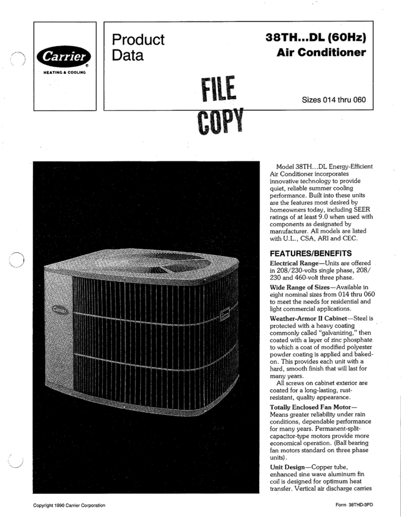
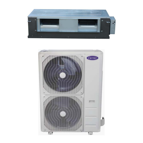
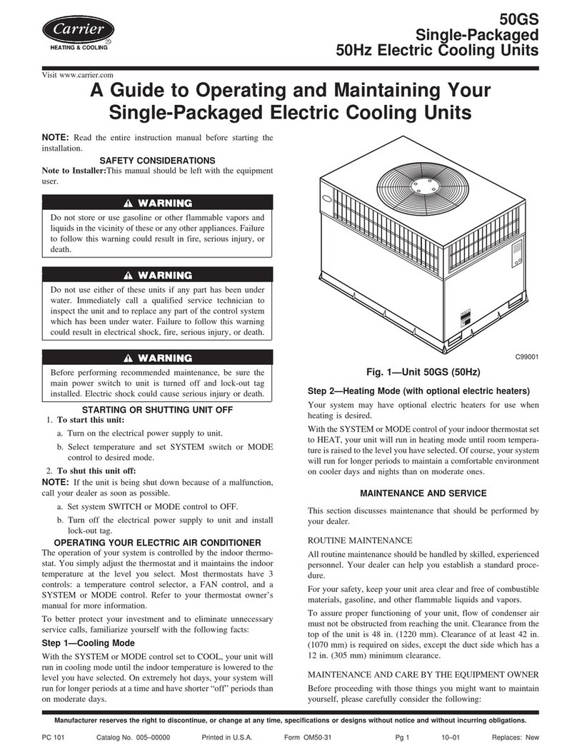
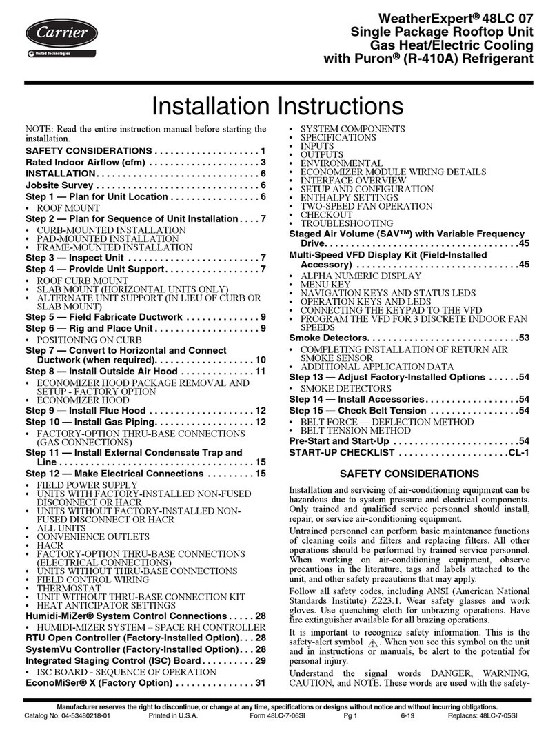
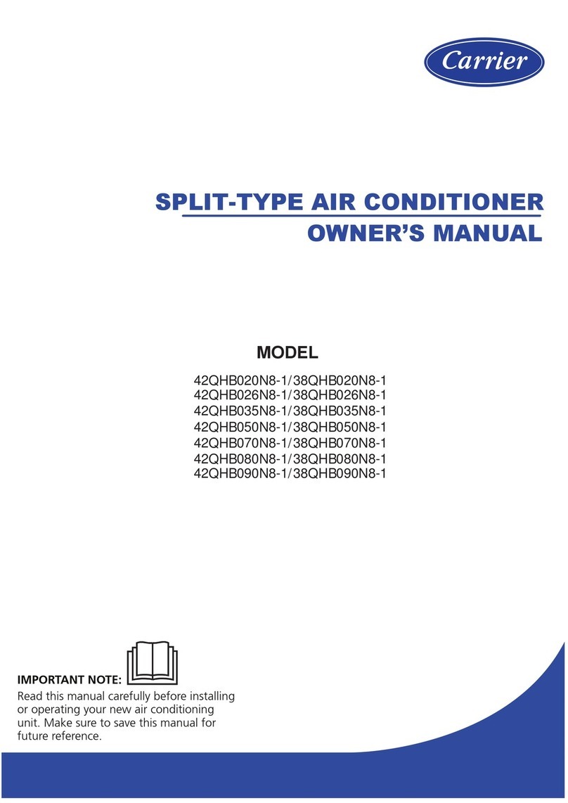
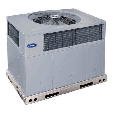
  9. Carrier AIRCONDITIONER ZC User manual

Carrier AIRCONDITIONER ZC User manual

Air Conditioner Owner`s Guide
Acondicionador de Aire Manual del Usuário
Climatiseur Manuel de L`utilisateur
READ THE OWNER` GUIDE BEFORE U ING
Por favor lea el manual detenidamente antes de usar su aire aire condicionado
Nota: Las instrucciones en Español empiezan en la página 26.
Lisez attentivement toutes les directives avant d`installer votore appareil.
Note: Les instruciones en Français commencent a la page 50.
MODEL ZC - Cool Only
ZH - Heat Cool
ZQ - Heat Pump
A FEW WORDS ABOUT YOUR NEW AIR CONDITIONER
Thank you for choosing a Carrier Air Conditioner! You can feel confident in your selection because the same
pride in craftsmanship and engineering knowledge that went into Carrier equipment installed in the Astrodome
in Texas, the Sistine Chapel in ome; the United States Capitol halls of Congress, and thousands of other
installations worldwide has gone into the construction of your unit.
One of the principal advantages of owning a Carrier room air conditioner with electric heat is that the unit
heats AND cools, so it can be used year-round! (Only on models with heat feature)
While cooling, your new Carrier unit also filters and dehumidifies. In cold weather, the unit gently heats
and circulates air throughout the room. Carrier room air conditioners with electric heat quietly give you
maximum cooling comfort!
This Owner's Guide will supply you with all the information you need for installing, operating and maintaining
your new unit. Take a few moments to discover how to get the most in cooling comfort and economical
operation from your new room air conditioner.
SOME SUGGESTIONS
1. To avoid installation difficulties, read instructions completely before starting. This publication
contains information pertinent to the installation and operation of your new room air conditioner.
2. When possible, install unit on a shaded side of the house or building.
CAUTION
Coil fins on chassis are sharp and chassis is heavy. Chassis removal can cause personal injury.
3. Make sure that wall mounting area is structurally sound enough to support the unit.
4. For heat units, the heat is not for primary source of heat.
5. oom air conditioners are designed to fit easily into standard double-hung windows.
However, some window frame design variations require changes to modification to
the window for safe, proper installation. If assistance is needed, please call your local Carrier
Distributor. If there is no distributor in your area, call 1-800-CA IE (227-7437).
1
2
3
4
5
6
7
8
9
10
11
12
RECEIVING THE AIR CONDITIONER
GETTING ACQUAINTED WITH THE AIR CONDITIONER
AIR CONDITIONER WITH REMOTE CONTROL
OPERATING THE ELECTRONIC UNIT WITH THE REMOTE CONTROL
OPERATING UNIT FROM THE CONTROL PANEL
(WITHOUT THE REMOTE CONTROL)
AIR DIRECTION AND EXHAU T CONTROL
TIP TO ACHIEVE MAXIMUM EFFICIENCY AND COMFORT
WHERE AND HOW TO IN TALL THE AIR CONDITIONER TO
ACHIEVE A BETTER PERFORMANCE
DRAIN Y TEM OPTION
AFETY IN TRUCTION
MAINTENANCE AND PRE ERVATION
PRACTICAL OLUTION
INDEX
INDICE / INDICE
4
5
6
7
11
12
13
14
17
22
22
24
1. RECEIVING THE AIR
CONDITIONER
ead the instructions in the User's Manual.
Keep the Manual. It is always useful.
Unpack the unit.
Check if the unit exterior is in perfect condition.
Check if the items provided with the unit are inside the
box.
1 - User's Manual
2 - Seal
3 - Drain pan
4 - Screws (4)
5 - emote control and batteries
6 - ear drain
In case there is any damage, or if one of the mentioned
items is missing, contact the store that sold it to you.
4
For your saf ty w ar glov s.
NOTE
Th window installation acc ssory kit
com s with cooling only units.
NOTE
5
2. GETTING ACQUAINTED WITH THE
AIR CONDITIONER
Check the appliance technical characteristics on the
nameplate.
Cabinet
A - Horizontal louvers for the air flow
B - Vertical louvers for the air flow
C - Air exhaust control
D - Safety screws (both sides)
E - Filter cover
F - Filter
G - Control panel
H - Front Grille
Na eplate
A - Model
B - Serial number
C - Voltage (V)
D - Circuit Breaker (A)
E - Cooling capacity (Btu/h and W)
F - Power consumption (W)
G - Current (A)
H - Power efficiency (W/W)
I - Heating capacity (Btu/h and W)
6
3. AIR CONDITIONER WITH REMOTE CONTROL
Control panel
Main display (indicates the selected temperature or mode)
In ord r to chang th t mp ratur unit from C lsius to Fahr nh it d gr s, or vic -v rsa,
simultan ously pr ss th S l ct button and (+) for 3 s conds on th control pan l.
On/Off
Energy Saver
Turbo mode
Heating mode
Temperature and Timer adjustment
Timer
Cooling mode
De-humidification mode
Fan mode
Speed setting
Sleep mode
Auto mode
1 - On/Off
2 - Filter cleaning indicator
3 - Timer on indicator
4 - Selector
Re ote control
Turbo
NOTE
7
4. OPERATING THE ELECTRONIC
UNIT WITH THE REMOTE CONTROL
Insert two 1.5 V AAA batteries (supplied with the
electronic model unit), opening the cover on the rear
of the remote control.
Ti er operation, turn the unit off or on at a
deter ined ti e (from 1 to 12 hours), press the Timer
button. If the unit is off, after the programming, it will
turn on at the end of the set time. If it is on, it will
turn off at the end of the period.
In order to set the ti e to turn on and off, press the
buttons (+) or (-) until the desired time (in number of
hours) is achieved.
When this function is activated, the corresponding
indicator remains lit on the panel.
The battery useful life is around one year.
Use only new batteries. Use only specified batteries.
To turn on or off the unit, press the On/Off button.
Th unit "b ps" v ry tim an
op ration is activat d.
NOTE
Th unit display will turn off 5 minut s
aft r th mod is activat d, and th Tim r
indicator will r main lit.
NOTE
To increase or reduce the te perature in the room,
press the buttons (+) or (-), as required.
To display the roo te perature, press buttons (+)
and (-) simultaneously for 3 seconds.
These buttons set the time hour by hour, up to 12 hours.
8
When this function is activated, the letter is displayed
on the panel.
To cool, press the Cooling mode button.
To heat, press the Heating function button.
When this function is activated, the letter is displayed
on the panel.
To canc l this function, pr ss th Tim r
button again, and s t th tim to z ro.
NOTE
Th t mp ratur rang s from 18ºC / 65°F
to 32ºC / 90°F. To s t th maximum or th
minimum, th unit b ps twic .
NOTE
Only for mod ls with h at f atur .
NOTE
9
When this function is activated, the letter is displayed
on the panel.
In order to circulate air (without cooling or heating),
press the Fan button.
When this function is activated, the letter is displayed
on the panel.
To auto atically adjust the unit according to the room
temperature variations, alternating between cool and
heat and high, medium or low speed, activate the Auto
mode.
The speed can be selected among one of the three
existing levels.
To set the fan speed, press the fan speed button.
The selected speed (air flow) will be indicated on the
control panel as follows:
To eli inate the air hu idity in the room, press the
De-humidification button. This function gradually
removes the room humidity, with little changes to the
temperature, providing more comfort.
When this function is activated, the letter is displayed
on the panel. The unit will always operate in low cooling.
Th Fan Function only circulat s th air in
th room.
NOTE
The Energy Saver function reduces the consumption of
power, turning off the fan when the compressor or
resistance is off. The function is activated and de-
activated by means of the remote control. When the
function is activated, the display exhibits the acronym
.
10
To save power, press the Energy Saver button.
In order to cool or heat the room quickly, set the
temperature as desired, and press the Turbo mode
button.
When this function is activated, the letter T is displayed
on the panel.
The Turbo function will turn off as soon as the selected
temperature is reached, and from then on, it will operate
in last selected mode.
To auto atically set the roo te perature during
sleep ti e, providing more cost-effectiveness and
comfort, activate the Sleep mode.
After this mode is activated, the unit will increase (in
cooling) or decrease (in heating) the set temperature
in 1ºC / 2°F per hour, during the first two hours,
remaining at this temperature for more than 6 hours.
When the total 8-hour period has elapsed, the unit will
return to the initial temperature. On the display,
will appear (sleep - to sleep).
Th unit display will turn off 5 minut s
aft r th mod activation, and th Tim r
indicator r mains.
NOTE
5. OPERATING UNIT FROM THE CONTROL PANEL
(WITHOUT THE REMOTE CONTROL)
11
To select any one of the functions on the unit, press
the Select button once, and the function programmed
will appear on the display. Then, press the button (+),
or the button (-), until achieving the desired function.
elease the button, and the unit will take on this new
programming.
Display
- Fan
- Cooling
- De-humidification
- Auto (Automatic)
- Heating (only for HOT/COOL models)
- Turbo
- Sleep
- Energy Saver
Next, the desired temperature can be set using the
buttons (+), or (-).
To change the fan speed, press the Select button
twice, and the display will exhibit the programmed
speeds, that is, F1, F2 or F3. Then, press the button
(+), or the button (-), until achieving the new speed.
elease the button, and the unit will take on this
new programming.
12
6. AIR DIRECTION AND EXHAUST
CONTROL
IMPORTANT
Th Exhaust function allows r moving th
us d air, smok , and odors from th room
and s nding th m to th outsid .
Four way air flow provided by the mobile
louvers.
When the vertical louvers are moved, the air
flow is directed to the left or to the right.
When the horizontal louvers are moved, the
air flow is directed up or downwards.
The air exhaust control is made through the
device located next to the louvers.
The use of exhaust control with the unit in
cooling or heating reduces the unit efficiency.
Therefore, we recommend to use it, whenever
necessary, in the Fan function.
For th h ating mod on th h at pump
mod ls, th l ctrical h at r start op rating.
Wh n th outsid t mp ratur drops b low
45º F (7º C).
NOTE
13
7. TIPS TO ACHIEVE MAXIMUM
EFFICIENCY AND COMFORT
Keep the air filter clean, and do not turn on the unit
without the air filter.
Do not wait until the room temperature gets too low or
too high. Turn on the unit before that.
Do not exaggerate in the temperature intensity (too hot
or too cold).
When turning on the air conditioner, keep doors, windows
and curtains closed.
These precautions increase the unit efficiency, and
reduce the power consumption.
Before sleeping, set the unit to low speed in order to
reduce the noise level.
Do not use the air conditioner to dry clothes, to preserve
food, and nor to acclimatize environments for animals
or plants.
During long periods when the air conditioner is not
used, turn it on for some minutes once a month. If the
model is HEAT /COOL, turn it on in heating mode.
Exagg rat d t mp ratur s wast n rgy.
Nominal
115V/60Hz
Minimum
104V
Maximum
127V
208-230/60Hz 187V 253V
The air conditioner has been designed to
operate withim the folowing voltage and
temperature conditions.
Voltage
MAXIMUM OUTSIDE TEMPE ATU E
Cooling..............maximum 109ºF (43°C)
1. Never obstruct the air circulation of the unit installing
it behind curtains, furniture or partition walls.
4. Install the air conditioner facing the largest
free area.
5. Pay attention to the minimum distances between
the external surface of the unit and the wall near
it. 9. In case of power outage, turn off the air conditioner
immediately, and turn it on again only 1 minute after
the power is re-established. This procedure will prevent
voltage variations that can cause damage to the
compressor.
10. Do not use the circuit breaker as an On-Off switch.
The circuit breaker is the main safety device of the
electric circuit.
/ 40
7. Avoid installing the outside surface of the air
conditioner turned to closed environments as roof
boards, garages, etc, the outside temperature might go
over the maximum operating temperature and damage
the unit.
8. Whenever you want to change from Cooling to Heating,
or vice versa, turn off the appliance, and wait for 3
minutes before turning it on again.
6. Comply with the minimum distance required for the
installation of more than one unit on a same wall.
14
Th l ctronic mod ls hav an automatic
prot ctiv d vic that allows r starting
th compr ssor only 3 minut s aft r th
shutdown.
NOTE
8. WHERE AND HOW TO INSTALL
THE AIR CONDITIONER TO ACHIEVE
A BETTER PERFORMANCE
2. Try to install the unit on a wall directed toward the
east, because the sunrays are less intense.
3. Avoid using this unit in Cooling with inside temperatures
lower than 20ºC / 68°F, so that the ice does not accumulate
in the inside heat exchanger.
THROUGH-THE-WALL INSTALLATION
15
WALL STUD
FRAME OR
BACK UP STRIP
FINISHED
OPENING
DIMENSIONS
26 3/16” (665mm)
17 5/16”
(440mm)
Window installation GW 05825004 instructions com
with th window acc ssory kit only for ZC mod ls. It is
availabl as an acc ssory for ZH and ZQ mod ls.
NOTE
Good framing construction practic s must
b follow d to nsur a saf , s cur and
prop rly install d unit.
CAUTION
6 3/4 (17 cm)
12 (30 cm)
45°
Through-the-wall installation can be made in wood
frame or masonry walls. The casing must be tipped to
the outside to aid in draining condensate. The installation
should be weatherproofed outside and finished
inside.Installations in wood framed or masonry walls
can be made using the casing as follows. Fasten the
casing directly to masonry or studding using masonry
or woodscrews. Adjust the outward tip front to rear, so
it drops from 3/16 to 3/8-in. (5-10-mm). If wall thickness
overlaps the side louver in unit casing,make wall opening
wider, as shown in Fig. below. If wall projects beyond
back of unit, use baffles onrear corners of casing.
Cut opening in wall. For dimensions see Fig. below.
Frame opening in wall. For wood framing,provide
a wooden framing support or other approved
structure for fastening casing to wall. See Fig.
for typical wood framing.
Tipical wood framing
For masonry framing, use a lintel to support wall
above opening. Mouting angles are sometimes
assembled to casing. Be sure to size the wall opening
to provide clearance for metal thickness of casing
and mouting angles if they are used. If mounting
angles are to be used with casing, position angles
as follows:
1. Flush with unfinished wall - plaster over or use
decorative molding.
2. Against finished wall - use decorative molding.
3. Inside wall opening - use decorative molding.
emove the two screws that hold the plastic front (one
at each side).
Unit casing should proj ct ½ (13mm) in to
room to nsur prop r fit of d corativ grill .
NOTE
16
Tip casing to outside. Tip is necessary for draining
condensate to the rear of the basepan, to allow for
excess condensation run-off. The tip also helps to
prevent leakage into the room by allowing excess water
to drain away from the building.
INSTALL CASING IN WALL
emove the plastic front.
emove the safety screw.
Be careful not to be injured by the metal parts.
Disconnect the ground wire and remove the unit
from the wrapper pulling it by the bottom.
The recommended outward tip is 3/16 to 3/8 in. (5 to 10
mm) from inside to outside. This means that back of
casing outside the room must be 3/16 to 3/8 in. (5 to 10
mm) lower than the front edge inside room.
9. DRAIN SYSTEM OPTIONS
R mov th r ar plug from th unit, and
install th drain (it m 6, pag 4).
NOTE
17
Hold tip angle and mark with chalk the location of
screw holes to be drilled in each side of the casing for
fastening in wall opening.
Drill 3 screw holes in each side of wood frame.
echeck outward tip.
Install the draining system for the condensing water
before positioning the unit in the cabinet. You must use
one of the two existing systems, depending on how,
and where the unit will be installed.
9.1 DRAINING SYSTEM THROUGH THE REAR
OUTLET
Pass a 5/8" (15,9 mm) plastic hose through the hole
located on the rear of the cabinet.
Th hos must b long nough to r ach th
rain wat r drain.
If unit is install d wh r cond nsat
drainag from th back of th unit can
drip onto p d strians or n ighboring
prop rty, us th xt rnal drain kit
suppli d with th unit. S installation
instructions on drain kit. - St p 9.
IMPORTANT
Chassis is h avy. Obtain h lp wh n lifting
to avoid p rsonal injury.
NOTE
The conditioner comes with the two drain holes closed
by plugs.
The conditioner is projected to use one of the three
function options:
1) No drain connection. That way provides the most
efficiency operation, but has splash noise, dripping
of rain water or condensate water.
2) ear drain, which provides a good efficiency for
operation and very low splash noise, or
3) Drain pan, which captures the most condensate and
does not have splash noise, but has lower efficiency
operation. Both the rear drain and the drain pan can
be connected to a hose and directed to a convenient
location on the ground, or a suitable floor drain.
18
Position the drain pan inside the cabinet.
9.2 DRAINING SYSTEM THROUGH THE BOTTOM
OUTLET (USING THE DRAIN PAN)
Install a 5/8" (15,9 mm) plastic hose at the outlet of
the drain pan.
Th hos must b long nough to r ach th
rain wat r drain.
Install one of the hose ends at the drain outlet.
The other end of the hose must be connected to the
water mains.
Th installation of this draining syst m is
not r comm nd d wh n th unit is
install d on sit s with difficult acc ss
( xampl : far from windows and insid
buildings), b caus it is difficult to conn ct
th hos to th wat r mains.
19
The other end of the hose must be connected to the
rain water drain.
Th installation of this draining syst m is
r comm nd d for most kinds of
installation (for xampl : on walls with
sash or on windows), sinc this mak s
asi r to conn ct th drain hos to th
rain wat r drain.
To g t th maximum p rformanc with th
low st pow r consumption, w r comm nd
using th draining syst m through th r ar
outl t.
IMPORTANT
INSTALLING THE UNIT IN THE CABINET
Two people must install the unit on the cabinet in order
to guarantee its perfect balance and alignment.
Tak car not to cr as or b nd th hos .
Lift the unit, align it with the cabinet, and slide it until
it is perfectly inserted.
Install the safety screw on both sides.
R mov th xisting plug in th insid
portion of th unit, th "high st on ",
locat d n xt to th l tt r "A".
IMPORTANT
S aling tap and flashing ar not includ d with
machin .
NOTE
20
Install the sealing tape and the flashing finishing.
Th unit is pr par d for this condition.
Install the plastic front, fastening it with two screws
(one on each side).
Positioning the cable on the power outlet side
Pow r cord is 55 in. (1,4 m) long and xt nds from
bottom of control pan l. S St p 24, if pow r cord
must b r locat d to opposit sid of unit. Do NOT
us a plug adapt r or xt nsion cord.
NOTE
Unit mod l/catalog numb r, s rvic /discr t numb r,
and s rial numb r can b found on th nam plat .
Wh n calling for information and s rvic , b sur
to provid th s rvic /discr t numb r.
NOTE
ELECTRICAL DATA
1. All wiring must comply with local and national electrical
codes. All wiring must be installed by qualified and
skilled electricians. If you have any questions regarding
the following instructions, contact a qualified electrician.
2. Check available power supply and solve any household
wiring problems BEFO E installing and operating this
unit.
3. An individual branch circuit and single receptacle used
only for this air conditioner, must be available. See Table
1 for suggested wire sizes for individual branch circuit.
4. For your safety and protection, this unit is grounded
through the power cord plug when plugged into a matching
wall outlet. If you are note sure whether your wall
outlet is properly grounded, please consult a
qualified electrician.
5. The wall outlet you select must macth the plug on the
unit power cord, and must be within reach of the installed
unit.
6. Follow fuse specifications indicated on unit
nameplate. See Table 2. Nameplate is located
above unit control panel inside the air discharge
section. For clear access to nameplate, front grille
must be removed as described on page 6.

This manual suits for next models

3

Other Carrier Air Conditioner manuals

Carrier 48SD User manual

Carrier

Carrier 48SD User manual

Carrier Infinity 50XL Operation manual

Carrier

Carrier Infinity 50XL Operation manual

Carrier 42KCR009713 User manual

Carrier

Carrier 42KCR009713 User manual

Carrier PAR524 User manual

Carrier

Carrier PAR524 User manual

Carrier 24ABC6 Quick start guide

Carrier

Carrier 24ABC6 Quick start guide

Carrier GA4S User manual

Carrier

Carrier GA4S User manual

Carrier WeatherMaker 48A020 User manual

Carrier

Carrier WeatherMaker 48A020 User manual

Carrier 48DL Dimensions and installation guide

Carrier

Carrier 48DL Dimensions and installation guide

Carrier AR TXHQB Series Repair manual

Carrier

Carrier AR TXHQB Series Repair manual

Carrier 42C Series Operation manual

Carrier

Carrier 42C Series Operation manual

Carrier PY4G K Series User manual

Carrier

Carrier PY4G K Series User manual

Carrier 48/50HC04---14 User guide

Carrier

Carrier 48/50HC04---14 User guide

Carrier CU-O Series User guide

Carrier

Carrier CU-O Series User guide

Carrier 40MBF/38MAQ User manual

Carrier

Carrier 40MBF/38MAQ User manual

Carrier 38CKC User manual

Carrier

Carrier 38CKC User manual

Carrier 40MBF Series User manual

Carrier

Carrier 40MBF Series User manual

Carrier 50ZP Series Assembly Instructions

Carrier

Carrier 50ZP Series Assembly Instructions

Carrier 48VL Instruction Manual

Carrier

Carrier 48VL Instruction Manual

Carrier DesertMaster 50TJM Installation guide

Carrier

Carrier DesertMaster 50TJM Installation guide

Carrier 40MBC Series User manual

Carrier

Carrier 40MBC Series User manual

Carrier 38QUS012 User manual

Carrier

Carrier 38QUS012 User manual

Carrier 38TPA024 SERIES300 Guide User manual

Carrier

Carrier 38TPA024 SERIES300 Guide User manual

Carrier 24ABB3 Operation manual

Carrier

Carrier 24ABB3 Operation manual

Carrier BLOW-THRU 37KM User manual

Carrier

Carrier BLOW-THRU 37KM User manual

Popular Air Conditioner manuals by other brands

American Standard 4A6V8024A1000B Service facts

American Standard

American Standard 4A6V8024A1000B Service facts

McQuay MCK020A Technical manual

McQuay

McQuay MCK020A Technical manual

Challenge MPPHA-05CRN1-QB6 instruction manual

Challenge

Challenge MPPHA-05CRN1-QB6 instruction manual

Bryant Evolution Extreme 186CNV installation instructions

Bryant

Bryant Evolution Extreme 186CNV installation instructions

Hitachi RAS-E10HB instruction manual

Hitachi

Hitachi RAS-E10HB instruction manual

Argo Relax Service manual

Argo

Argo Relax Service manual

OMAS Air-Fi AFT7 Installer and User Instruction Manual

OMAS

OMAS Air-Fi AFT7 Installer and User Instruction Manual

air choice TY-EA-03 user manual

air choice

air choice TY-EA-03 user manual

Mitsubishi Electric Mr.Slim PEA-M200 installation manual

Mitsubishi Electric

Mitsubishi Electric Mr.Slim PEA-M200 installation manual

Hitachi RAS-70YHA1 instruction manual

Hitachi

Hitachi RAS-70YHA1 instruction manual

Frigidaire GHWQ103WC1 use & care

Frigidaire

Frigidaire GHWQ103WC1 use & care

Haier HW-18LMA03(T3) Operation manual

Haier

Haier HW-18LMA03(T3) Operation manual

GE ASQ12AL Dimensions and installation information

GE

GE ASQ12AL Dimensions and installation information

Samsung AQ09F Series user manual

Samsung

Samsung AQ09F Series user manual

Electrolux KSV26HRC Diagnostic manual

Electrolux

Electrolux KSV26HRC Diagnostic manual

Yumpu YCP024F1L-M Installation operation & maintenance

Yumpu

Yumpu YCP024F1L-M Installation operation & maintenance

Fujitsu AU G45LRLA Series Design & technical manual

Fujitsu

Fujitsu AU G45LRLA Series Design & technical manual

Friedrich MR09C1H Brochure & specs

Friedrich

Friedrich MR09C1H Brochure & specs

manuals.online logo
manuals.online logoBrands
  • About & Mission
  • Contact us
  • Privacy Policy
  • Terms and Conditions

Copyright 2025 Manuals.Online. All Rights Reserved.