Step 9—Compressor Crankcase Heater
When equipped with a crankcase heater, energize heater a mini-
mum of 24 hr before starting unit. To energize heater only, set
thermostat to OFF and close electrical disconnect to outdoor unit.
A crankcase heater is required if the refrigerant tubing is longer
than 50 ft.
Step 10—Install Electrical Accessories
Refer to the individual instructions packaged with the kits or
accessories when installing.
Step 11—Start-Up and Check Charge
Do not operate unit in the vicinity of toxic or flammable
material. Failure to follow this warning can result in personal
injury, fire, or death.
To prevent compressor damage or personal injury, observe
the following:
•Do not overcharge system with refrigerant.
•Do not operate unit in a vacuum or at negative pressure.
•Do not disable low-pressure switch In scroll compressor
applications:
•Dome temperatures may be hot.
To prevent personal injury wear safety glasses, protective
clothing, and gloves when handling refrigerant and observe
the following:
•Back seating service valves are not equipped with Schrader
valves. Fully back seat (counter clockwise) valve stem before
removing gage port cap.
•Front seating service valves are equipped with Schrader
valves.
Do not vent refrigerant to atmosphere. Recover during system
repair or final unit disposal.
1. If equipped with a crankcase heater, energize a minimum of
24 hr before starting unit. To energize heater only, set
thermostat OFF and close electrical disconnect to outdoor
unit.
2. Fully open liquid and vapor service valves.
3. Unit is shipped with valve stem(s) front seated and caps
installed. Replace stem caps after system is opened to refrig-
erant flow. Replace caps finger tight and tighten additional
1/12 turn using a backup wrench on valve body flats to prevent
distortion of sheet metal.
4. Close electrical disconnects to energize system.
5. Set room thermostat at desired temperature.
6. Set room thermostat to HEAT or COOL and fan to ON or
AUTO mode, as desired. Operate unit for 15 minutes. Check
system refrigerant charge.
7. Factory charge is shown on unit rating plate. Adjust charge in
cooling mode by following procedure shown in charging
table. Check charge in heating mode by following procedure
shown on heating check chart. Both are located on unit.
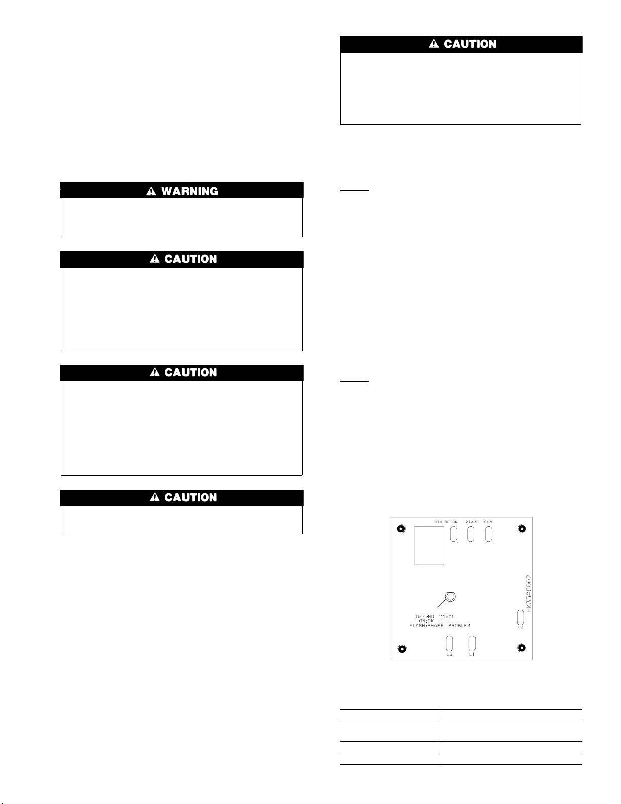
•3-phase scroll compressors are rotation sensitive.
•A flashing LED on phase monitor indicates reverse rotation.
(See Fig. 9 and Table 3.)
•This will not allow contactor to be energized.
•Disconnect power to unit and interchange 2 field wiring
leads on unit contactor.
SEQUENCE OF OPERATION —With power supplied to indoor
and outdoor units, transformer is energized. Defrost control board
is equipped with 5-minute lockout timer which may be initiated
upon any interruption of power.
Cooling
On a call for cooling, the thermostat makes circuits R-O, R-Y, and
R-G. Circuit R-O energizes reversing valve, switching it to cooling
position. On three phase models with scroll compressors, the units
are equipped with a phase monitor to detect if the incoming power
is correctly phased for compressor operation. (See Fig. 9 and Table
3.) If phasing is correct, circuit R-Y energizes contactor, starting
outdoor fan motor and compressor circuit. R-G energizes indoor
unit blower relay, starting indoor blower motor on high speed.
NOTE: If the phasing is incorrect, the contactor will not be
energized. To correct the phasing, interchange any two of the three
power connections on the field side.
When thermostat is satisfied, its contacts open, de-energizing
contactor and blower relay. Compressor and motors stop.
NOTE: If indoor unit is equipped with a time-delay relay circuit,
the blower runs an additional 90 sec to increase system efficiency.
Heating
On a call for heating, the thermostat makes circuits R-Y and R-G.
If phasing is correct, circuit R-Y energizes contactor, starting
outdoor fan motor and compressor. Circuit R-G energizes indoor
blower relay, starting blower motor on high speed.
Should the temperature continue to fall, R-W2 is made through the
second-stage room thermostat bulb. Circuit R-W2 energizes a
sequencer, bringing on the first bank supplemental electric heat
and providing electrical potential to the second heater sequencer (if
used). If outdoor temperature falls below the setting of the outdoor
thermostat (field-installed option), contacts close to complete the
circuit and bring on the second bank of supplemental electric heat.
Table 3—Phase Monitor LED Indicators
LED STATUS
OFF No call for compressor
operation
FLASHING Reversed phase
ON Normal
Fig. 9—Phase Monitor Control A00010
7