10 Specifications subject to change without notice. RHV-090-120-01SI
INSTALLATION
Jobsite Survey
Complete the following checks before installation.
1. Consult local building codes and the NEC (National
Electrical Code) ANSI/NFPA 70 for special
installation requirements.
2. Determine unit location (from project plans) or select
unit location.
3. Check for possible overhead obstructions which may
interfere with unit lifting or rigging.
Step 1 — Plan for Unit Location
Select a location for the unit and its support system (curb or
other) that provides for minimum clearances required for
safety (including clearance to combustible surfaces), unit
performance and service access below, around and above
unit as specified in unit drawings. See Fig. 2 on page 5 or
Fig. 3 on page 8.
NOTE: Consider also the effect of adjacent units.
Unit may be installed directly on wood flooring or on Class
A, B, or C roof-covering material when roof curb is used.
Do not install unit in an indoor location. Do not locate air in-
lets near exhaust vents or other sources of contaminated
air.
Although unit is weatherproof, avoid locations that permit
water from higher level runoff and overhangs to fall onto
unit.
Select a unit mounting system that provides adequate
height to allow installation of condensate trap per require-
ments. Refer to Install External Condensate Trap and Line
on page 15 for required trap dimensions.
ROOF MOUNT
Check building codes for weight distribution requirements.
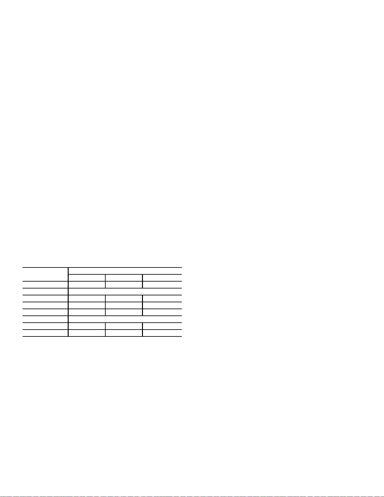
Unit operating weight is shown in Table 2.
Table 2 — Operating Weights
Step 2 — Plan for Sequence of Unit
Installation
The support method used for this unit will dictate different
sequences for the steps of unit installation. For example, on
curb-mounted units, some accessories must be installed on
the unit before the unit is placed on the curb. Review the
following for recommended sequences for installation steps.
CURB-MOUNTED INSTALLATION
1. Install curb
2. Install field-fabricated ductwork inside curb
3. Install accessory thru-base service connection pack-
age (affects curb and unit) (refer to accessory
installation instructions for details)
4. Prepare bottom condensate drain connection to suit
planned condensate line routing (refer to Install
External Condensate Trap and Line on page 15 for
details)
5. Rig and place unit
6. Install outdoor air hood
7. Install condensate line trap and piping
8. Make electrical connections
9. Install other accessories
PAD-MOUNTED INSTALLATION
1. Prepare pad and unit supports
2. Check and tighten the bottom condensate drain
connection plug
3. Rig and place unit
4. Convert unit to side duct connection arrangement
5. Install field-fabricated ductwork at unit duct openings
6. Install outdoor air hood
7. Install condensate line trap and piping
8. Make electrical connections
9. Install other accessories
FRAME-MOUNTED INSTALLATION
Frame-mounted applications generally follow the sequence
for a curb installation. Adapt as required to suit specific
installation plan.
Step 3 — Inspect Unit
Inspect unit for transportation damage. File any claim with
transportation agency.
Confirm before installation of unit that voltage, amperage
and circuit protection requirements listed on unit data plate
agree with power supply provided.
On units with hinged panel option, check to be sure all
latches are snug and in closed position.
Locate the carton containing the outside air hood parts. Do
not remove carton until unit has been rigged and located in
final position.
Step 4 — Provide Unit Support
ROOF CURB MOUNT
Accessory roof curb details and dimensions are shown in
Fig. 4 (on page 11). Assemble and install accessory roof
curb in accordance with instructions shipped with the curb.
Curb should be level. This is necessary for unit drain to
function properly. Unit leveling tolerances are shown in
Fig. 5 (on page 12). Refer to Accessory Roof Curb
Installation Instructions for additional information as
required.
Install insulation, cant strips, roofing felt, and counter flash-
ing as shown. Ductwork must be attached to curb and not to
the unit. The accessory thru-the-base power and gas
connection package must be installed before the unit is set
on the roof curb.
If electric and control wiring is to be routed through the
basepan, attach the accessory thru-the-base service
connections to the basepan in accordance with the
accessory installation instructions.
NOTE: The gasketing of the unit to the roof curb is critical
for a watertight seal. Install gasket supplied with the roof
curb as shown in Fig. 4. Improperly applied gasket can also
result in air leaks and poor unit performance.
RHV UNIT LB (KG)
090 102 120
Base Unit 743 (337) 805 (365) 978 (444)
Economizer
Vertical 75 (34) 75 (34) 75 (34)
Horizontal 122 (55) 122 (55) 122 (55)
Powered Outlet 35 (16) 35 (16) 35 (16)
Curb
14 in. (356 mm) 143 (65) 143 (65) 143 (65)
24 in. (610 mm) 245 (111) 245 (111) 245 (111)