Carrier COMFORTLINK 48HG014 User manual

Manufacturer reserves the right to discontinue, or change at any time, specifications or designs without notice and without incurring obligations.
PC 111 Catalog No. 534-80230 Printed in U.S.A. Form 48/50H,P-14SI Pg 1 3-05 Replaces: New
Book1144
Tab 1a1b6a6b
Installation Instructions
Power Exhaust Part Numbers: CRPWREXH018B00,
CRPWREXH019B00, CRPWREXH020B00
Barometric Relief Part Number: CRBARRLF003B00
CONTENTS
SAFETY CONSIDERATIONS ......................1
GENERAL ...................................... 1,2
INSTALLATION ................................. 2-6
Barometric Relief Damper ........................6
SAFETY CONSIDERATIONS
Installation and servicing of air-conditioning equipment can
be hazardous due to system pressure and electrical compo-
nents. Only trained and qualified service personnel should
install, repair, or service air-conditioning equipment.
Untrained personnel can perform the basic maintenance
functions of cleaning coils and filters and replacing filters. All
other operations should be performed by trained service
personnel. When working on air-conditioning equipment,
observe precautions in the literature, tags and labels attached to
the unit, and other safety precautions that may apply.
GENERAL
Consult price pages for the economizer accessory if the unit
is not already equipped. Refer to Table 1 for a complete list of
parts contained in each kit.
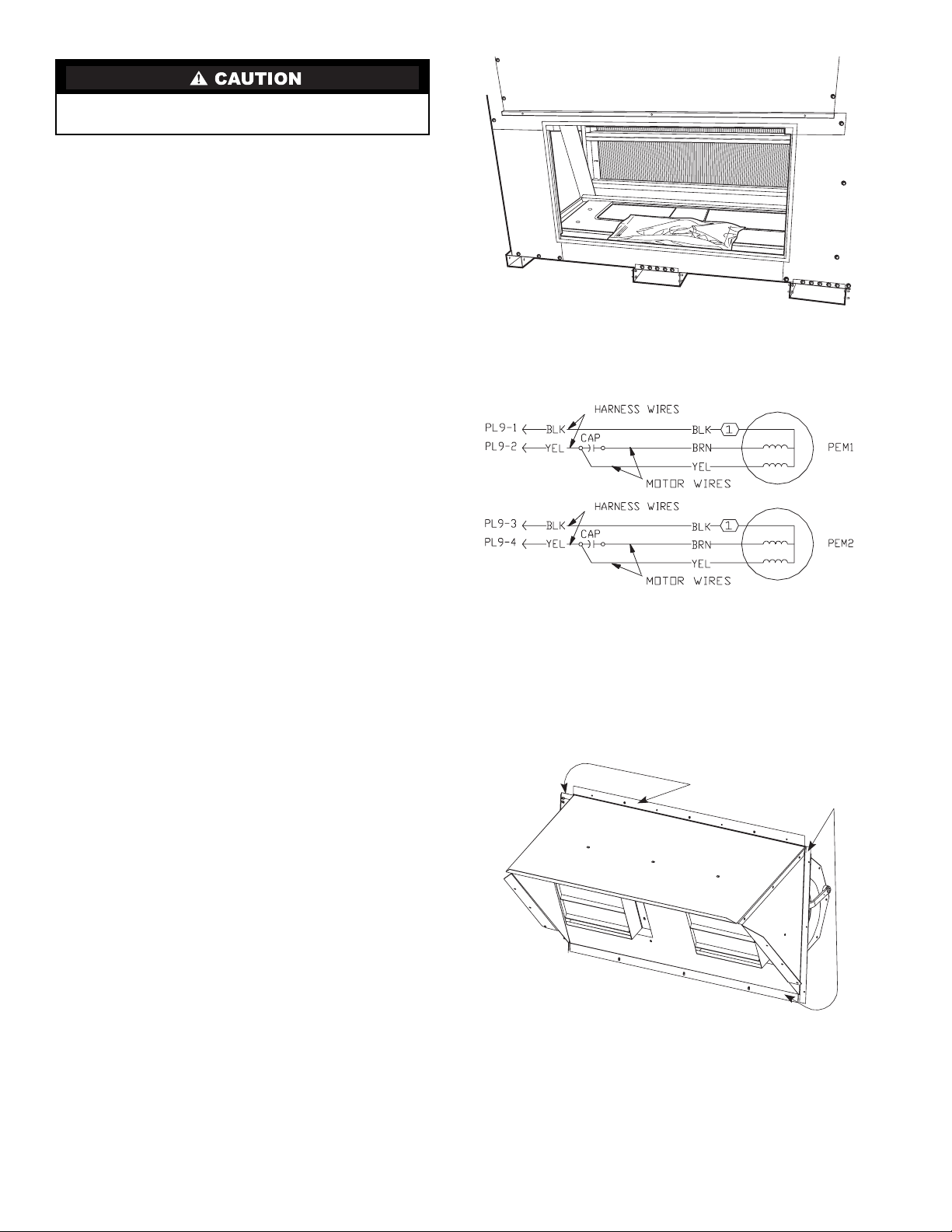
Each hood assembly has 2 power exhaust blowers.
Brackets, wires and extra gasket screws are also included in the
package.
POWER EXHAUST PACKAGE USAGE
Table 1 — Power Exhaust/Barometric Relief Parts List
IMPORTANT: There are two different design revision
48/50HG units currently being produced. Because of
these differences, there are two different versions of
this accessory. This accessory literature covers acces-
sories manufactured for units with design revision 1.
Design revision 0 units are not covered in this acces-
sory book.
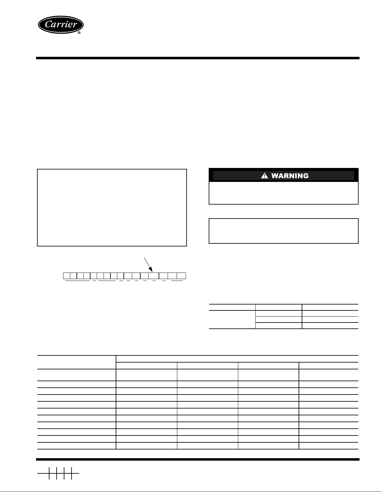
To determine the design revision, refer to the full unit
model number. See Fig. 1 for an example of an HG
model number. The design revision number in the model
number nomenclature is located in position 13.
Turn off main power to the unit and tag disconnect switch
before performing service or maintenance operations. Elec-
trical shock could cause personal injury or death.
IMPORTANT: The power exhaust accessory requires
the use of the economizer. Power Exhaust will not
operate without the use of an economizer.
UNIT VOLTAGE PART NUMBER
48/50HG014-028,
48/50PG20-28
208/230 V CRPWREXH018B00
460 V CRPWREXH019B00
575 V CRPWREXH020B00
ITEM DESCRIPTION DESCRIPTION (QUANTITY)
CRPWREXH018B00 CRPWREXH019B00 CRPWREXH020B00 CRBARRLF003B00
Blower/Damper
Assembly
Power Exhaust
(208/230 V)
Power Exhaust
(460 V)
Power Exhaust
(575 V) Barometric Relief
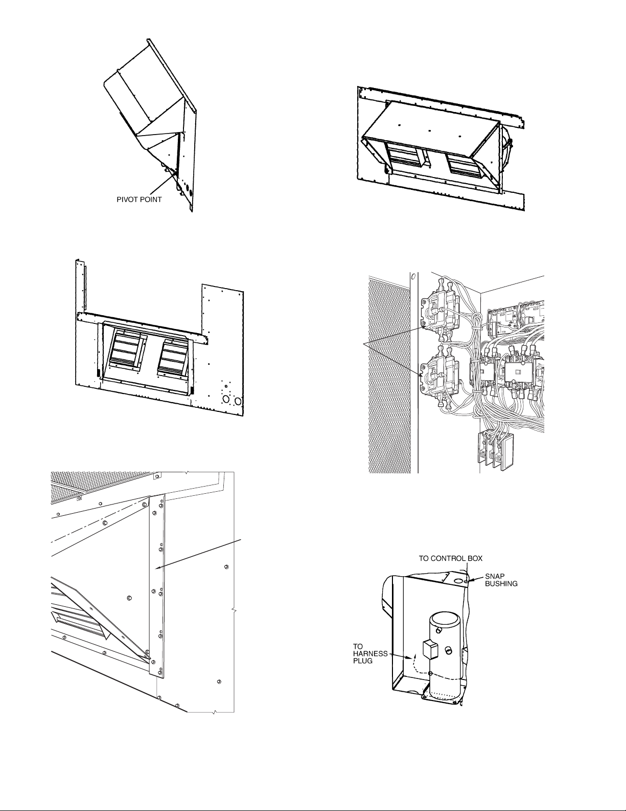
Contactor HN52KC010 (2) HN52KC010 (2) HN52KC010 (2) —
Screw 8-18 x 1/2
″AL56AU166 (4) AL56AU166 (4) AL56AU166 (4) —
Power Wiring Harness 50TG402807 50TG402807 50TG402807 —
Control Wiring Harness 50TG403083 50TG403083 50TG403083 —
Snap Bushing HY93NH091 HY93NH091 HY93NH091 —
Plug Plate 50TG500128 50TG500128 50TG500128 —
Left Hand Bracket 50TG502765 50TG502765 50TG502765 50TG502765
Right Hand Bracket 50TG502865 50TG502865 50TG502865 50TG502865
Screw - 1/4
″x3/4
″AL31AZ308 (9) AL31AZ308 (9) AL31AZ308 (9) AL31AZ308 (9)
Seal Strip ————
48/50HG014-028, 48/50PG20-28
with
COMFORT
LINK™ Controls
Power Exhaust and
Barometric Relief Accessory
Fig. 1 — Model Number Chart
PositionNo.12345678 9 10 11 12 13 14 15 16
Example:48HGD016AA C 611AA
DESIGN REVISION NUMBER

2
INSTALLATION
1. Remove return end cover and save screws for reuse. See
Fig. 2.
2. As shown in Fig. 3, the power exhaust motor is factory
wired to terminal 1 (high speed). To change motor speed,
move the black wire from terminal 1 to terminal 2 (medi-
um speed) or terminal 3 (low speed). If high speed is
desired, no wiring changes are required. The motor
closest to the control box is PEM1. The motor furthest
away from the control box is PEM2.
3. Position the power exhaust damper assembly at the return
end of the unit. Add seal strip to the edges of the hood
assembly. See Fig. 4. The long piece of seal strip is for the
top and bottom and the short piece is for the two sides.
4. Remove patch plate attached to the bottom of the com-
pressor partition behind compressor B1. Save screws.
5. Feed 6-pin connector of the motor harness through hole
created by the removal of the patch plate. Pull as much
wire through the hole as possible without causing damage
to the harness.
6. Place the power exhaust/damper assembly into the unit.
The accessory should pivot on the unit end panel. See
Fig. 5.
7. Fold power exhaust/damper assembly back into the unit
asshowninFig.6.
8. Install the side brackets using the screws included (1/4x
3/4-in.). Be sure to properly position the hood. See Fig. 7.
9. Tilt the assembly out of the unit and into final operating
position. See Fig. 8.
10. Secure the assembly using the screws removed earlier
from Step 1.
11. Snap the 6-pin connector of the control box harness into
the plug plate provided with the accessory.
12. Plug the 6-pin connectors together (PL9). Bundle up
excess wire in the motor harness and secure with a
wire tie. When bundling wires, be sure to gather wires
as close as possible to compressor partition so as to
reduce the overall length of the wires. Push excess
wire through hole in partition. Secure plate with
screws originally used to secure patch plate. This will
ensure that the extra wire length will not come into
contact with moving parts.
13. Remove the control box cover and install the two power
exhaust contactors to the side of the control box using the
screws included with the kit (8-18 x 1/2-in.). See Fig. 9.
14. Install the plastic snap bushing into the bottom of the con-
trol box as shown in Fig. 10.
15. Route the power exhaust harness through the compressor
section and into the control box, through the snap bush-
ing. See Fig. 10.
16. Connect the wires of the harness in the control box as
shown in the wiring diagram. The harness wires are
labeled to match the corresponding component and
connection position.
When removing panels from the unit, be careful not to
damage roof or other surfaces with the panels.
Fig. 2 — Unit Return End (48/50HG Units)
LEGEND
Fig. 3 — Power Exhaust Motor Wiring
(48/50HG Units)
CAP — Capacitor
PEM — Power Exhaust Motor
PL — Plug
Fig. 4 — Hood Assembly

3
17. 48/50HG028 208/230-v Units only:
Do not install control wiring harness included with the
accessory. The control wires for the power exhaust
contactors are included with the unit harness as a bundle
and can be connected to the appropriate terminals on the
contactors. See Fig. 11.
All other units:
Install control wiring harness as indicated in Fig. 12.
18. Dress the wiring in the control box so that the wires are
adequately supported and secured using the wire ties
supplied.
19. Replace the control box cover.
20. Re-apply power to the unit.
21. The ComfortLink™ control can now be configured to
operate the power exhaust. To do this the unit must be
configured for Power Exhaust Enabled (default is
DISABLED), Power Exhaust 1 Percentage setting
(default is 40%), Power Exhaust 2 Percentage setting
(default is 75%). These configurations are accomplished
through the Scrolling Marquee Display by using the
Configuration menu.
22. The control system must be configured to use the power
exhaust. A password may be required to edit the configu-
rations, depending on the previous settings configured in
the unit. Default password is “1111”.
23. To access the configuration, use the arrow keys to scroll
the red LED on the display to the “Configuration”
position and press . Use the arrow keys to scroll
down until the display reads “ECON”, and press the
key. At the Power Exhaust Enabled (PE.EN)
setting, press twice. The display should be
flashing DSBL. Use the arrow keys to change the
configuration to “ENBL” and press and then
. Use the arrow keys to scroll down to the
Power Exhaust 1 Percentage setting (PE1.P) and press
twice. Use the arrow keys to increase or
decrease the economizer position percentage that will
start the first power exhaust fan, and press and
.Usethearrowkeystoscrolldowntothe
Power Exhaust 2 setting (PE2.P) and press
twice. Use the arrow keys to increase or decrease the
economizer position percentage that will start the second
power exhaust fan, and press and .
24. Configuration of the power exhaust is now complete.
Pressing the key several times will return the
display to the auto scroll setting.
25. Consult the Controls and Troubleshooting Guide for
complete instructions on using the ComfortLink control
system.
26. The unit is now ready for normal operation.
ENTER
ENTER
ENTER
ENTER
ESCAPE
ENTER
ENTER
ESCAPE
ENTER
ENTER ESCAPE
ESCAPE

4
BRACKET
POWER
EXHAUST
CONTACTOR
Fig. 8 — Assembly in Operating Position
Fig. 10 — Compressor Section
Fig. 6— Power Exhaust/Relief Damper Assembly
Fig. 7— Bracket and Hood Positioning
Fig. 9 — Control Box Detail
Fig. 5 — Pivot Point on Unit Panel

5
GRN/YEL
SECONDARY
24V V24
TRAN3
24V
ECONO
CONTROL
BOARD
(ECB)
2
1
1
2
3
3
4
4
J2
FIOP/
ACCESSORY
4
6
16
17
2
3
J8
1
2
1
3
J7
1
C2C1 PEC
2
C2C1 PEC
1
RED
BLU
BRN
18
5
RED
RED
3
2
1
1
2
3
3
4
5
J4
2
1
1
3
2
4
J5
5
4
6
7
9
8
4
6
3
6
5
4
3
2
1
2
5
5
6
6
2
1
J9
1
2
C.A1
3.2 AMPS
CB3
RED
C2
BRN
BRN
Fig. 11 — Power Exhaust Wiring Diagram — 48/50HG028 208/230-v Units
LEGEND
C—Contactor
CAP — Capacitor
ECB — Economizer Control Board
FIOP — Factory-Installed Option
FU — Fuse
IAQ — Indoor-Air Quality
OAQ — Outdoor-Air Quality
PEC1 — Power Exhaust Contactor
PEM — Power Exhaust Motor
PL — Plug
Fig. 12 — Power Exhaust Wiring Diagram — All Units Except 48/50HG028 208/230-v Units
LEGEND
C—Contactor
CAP — Capacitor
CB — Circuit Breaker
ECB — Economizer Control Board
FIOP — Factory-Installed Option
FU — Fuse
PEC — Power Exhaust Contactor
PEM — Power Exhaust Motor
PL — Plug
TRAN — Transformer

6
Barometric Relief Damper
1. Remove return end cover. Save screws for reuse. See
Fig. 2.
2. Position the barometric relief assembly at return end of
unit. Add seal strip to the edges of the hood assembly. See
Fig. 4. The long piece of seal strip is for the top and bot-
tom. The short piece is for the two sides.
3. Place the barometric relief assembly into the unit. The
accessory should pivot on the unit end panel. See Fig. 5.
4. Fold barometric relief assembly back into the unit. See
Fig. 6.
5. Install the side brackets using the 1/4x3/4-in. screws. Be
sure to properly position the hood. See Fig. 7.
6. Tilt the assembly out of the unit and into final operating
position. See Fig. 8.
7. Secure the assembly using the screws removed from
Step 1.


Manufacturer reserves the right to discontinue, or change at any time, specifications or designs without notice and without incurring obligations.
PC 111 Catalog No. 534-80230 Printed in U.S.A. Form 48/50H,P-14SI Pg 8 3-05 Replaces: New
Book1144
Tab 1a1b6a6b
Copyright 2005 Carrier Corporation
Other manuals for COMFORTLINK 48HG014
1
This manual suits for next models
11
Table of contents
Other Carrier Ventilation Hood manuals
Popular Ventilation Hood manuals by other brands

Siemens
Siemens LC91BUR50 Instructions for installation and use

BOMANN
BOMANN DU 771.1 G Nstruction manual

Siemens
Siemens LC65KDK20 User manual and installation instructions

myappliances
myappliances SPLASHBACK user manual

NEFF
NEFF D 8662N0 Operating and installation instructions

AEG
AEG DI 8820 OPERATING AND INSTALLATION Manual