Cartft FLEETPC-ARM-300 User manual

FLEETPC-
ARM-300
Series
Reference Manual
All manuals and user guides at all-guides.com
all-guides.com

FLEETPC-
A
RM-300 Se
r
ies
Page
2
Release Notes
Version Release Date Notes By
1.0 January , 2017 The 1s
t
Release to Customer
1.1 March, 2017 Add additional features
1.2
June, 2017 Add GPIO device names
Correct LED1 pin assignment
Disclaimer
This documentation is provided for use with CarTFT.com products. No license to
CarTFT.com property rights is granted. CarTFT.com assumes no liability and provides
no warranty either expressed or implied relating to the usage or intellectual property right
infringement that may result from its use.
CarTFT.com provides this document “as is,” without warranty of any kind, expressed or
implied, including, but not limited to, its particular purpose. CarTFT.com may make changes
to this document without notice.
All manuals and user guides at all-guides.com

Page
3
FLEETPC-
A
RM-300 Se
r
ies Ha
r
dwa
r
e
Table of Contents
TABLE OF CONTENTS ............................................................................................ 3
1 PRECAUTIONS ................................................................................................ 5
1.1 Safety Precautions .......................................................................................... 5
1.2 Write Prohibited Regions ................................................................................. 6
1.3 Warranty ........................................................................................................ 6
2 PRODUCT FEATURES ...................................................................................... 7
2.1 Overview ........................................................................................................ 7
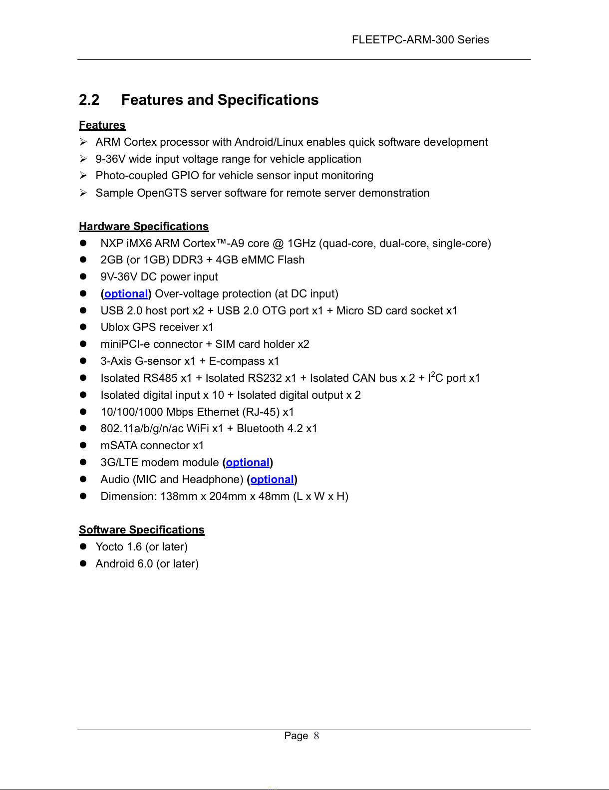
2.2 Features and Specifications ............................................................................. 8
2.3 Block Diagram ................................................................................................ 9
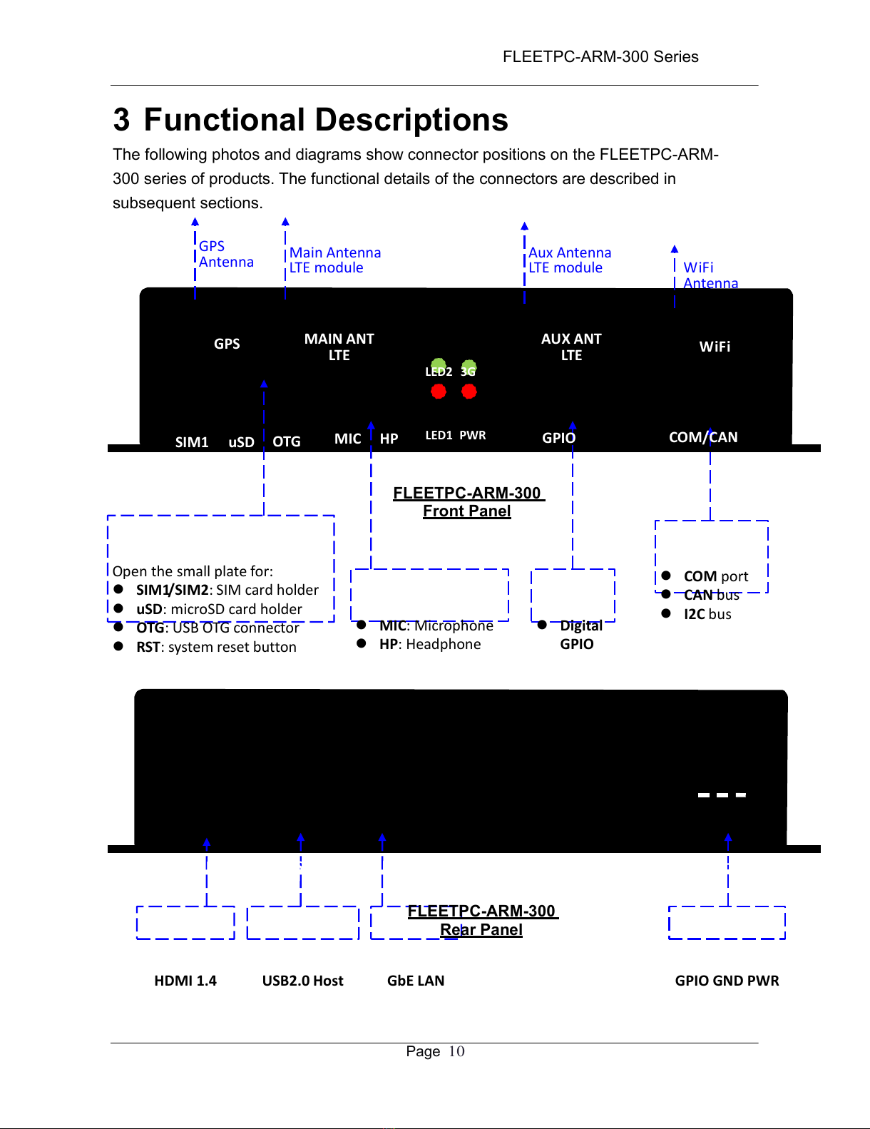
3 FUNCTIONAL DESCRIPTIONS ........................................................................ 10
3.1 Power Supply and MCU Power ON/OFF ........................................................ 11
3.2 System Power Management .......................................................................... 16
3.3 Console and Debug Port ............................................................................... 18
3.4 IO Isolation ................................................................................................... 21
3.5 IO1 (COM/CAN) Connector ........................................................................... 22
3.6 IO2 (GPIO) Connector................................................................................... 26
3.7 USB Connectors ........................................................................................... 30
3.8 GPS Receiver............................................................................................... 32
3.9 miniPCIe Connector (for 3G/LTE modem)....................................................... 33
3.10 WiFi and Bluetooth ...................................................................................... 34
3.11 G-Sensor & e-Compass ............................................................................... 35
3.12 Ethernet ..................................................................................................... 36
3.13 mSATA Connector ....................................................................................... 37
3.14 Audio (optional)........................................................................................... 38
3.15 Unique CPU ID ........................................................................................... 39
3.16 LED ........................................................................................................... 40
3.17 Keypad Connector ...................................................................................... 41
3.18 MicroSD Connector ..................................................................................... 41
3.19 BM Connectors (Firmware Update) .............................................................. 43
3.20 Other functions ........................................................................................... 44
4 OUTLINE DRAWING ....................................................................................... 45
5 ELECTRICAL SPECIFICATIONS ...................................................................... 46
All manuals and user guides at all-guides.com

Page
4
FLEETPC-
A
RM-300 Se
r
ies Ha
r
dwa
r
e
APPENDIX A: GPIO PHOTO-COUPLER SPEC ........................................................ 47
APPENDIX B: UART/CAN PHOTO-COUPLER SPEC ............................................... 49
APPENDIX C: DC-IN MATING CONNECTOR SPECIFICATIONS ............................... 52
APPENDIX D: DC-IN CONNECTOR SPECIFICATION .............................................. 53
APPENDIX E: IO2 (GPIO) MATING CONNECTOR SPECIFICATION .......................... 54
APPENDIX F: IO2 (GPIO) CONNECTOR SPECIFICATION ....................................... 55
All manuals and user guides at all-guides.com

Page
5
FLEETPC-
A
RM-300 Se
r
ies
1 Precautions
1.1 Safety Precautions
In order to use this product safely, please take special note of the following precautions.
•
Read all product manuals and related documentation before using this product. Use
this product correctly and safely. Follow all warnings.
•
If operating or extending this product in a manner not described in this manual,
please do so at your own risk. Be sure to fully read this manual and other technical
information on our website and proceed safely and responsibly.
•
Do not install this product in a place with a lot of water, moisture, dust or soot. This
could cause product failure, fire, or an electric shock.
•
Some parts of this product generate heat and can reach high temperatures. This
may cause burns if it is improperly handled. Do not touch the electronic components
or surrounding area while powered on or immediately after being turned off.
•
Carry out any design and development only after you have thoroughly read and
understood this manual and any other related technical materials on the website or
in the data sheets. Test your product thoroughly for reliability and safety.
•
This product is not intended for applications that require extremely high reliability,
safety, functionality and accuracy: including but not limited to medical equipment,
traffic control systems, combustion control systems, and safety equipment. This
company is not liable for death or injury if used in such systems.
•
This product uses semiconductor components designed for generic electronics
equipment such as office automation, communications, measurement equipment
and machine tools. Foreign noise or a power surge may cause this product to
malfunction or fail.
•
To ensure there is no risk of bodily harm or property damage, be sure to take all
electrical safety precautions such as protection circuits, limit switches, fuse breakers,
or redundant systems. Only use the device after sufficient reliability and safety
measures are in place.
All manuals and user guides at all-guides.com

Page
6
FLEETPC-
A
RM-300 Se
r
ies
1.2 Write Prohibited Regions
Data stored by the EEPROM, i.MX6 electrical fuse (e-Fuse) is used by the software
contained in this product. Do not write to these regions as this may cause the product
stop working correctly. Purposely writing to these regions voids the product warranty.
1.3 Warranty
As described in the Product Warranty Policy provided with this product, the main board is
covered by a one year replacement warranty starting from the time of purchase. Please
note that the other included goods and software are not covered under this warranty. Some
knowledge used by CARTFT.COM is provided by third parties, and CARTFT.COM makes
no representation or warranty as to the accuracy of such information.
All manuals and user guides at all-guides.com
all-guides.com

Page
7
FLEETPC-
A
RM-300 Se
r
ies
Order
Code
Over-Voltage
Protection
No
-V Yes
2 Product Features
2.1 Overview
The FLEETPC-ARM-300 is a communication gateway designed for in-vehicle
applications or IOT (Internet of Things) applications. The FLEETPC-ARM-300 offers
some unique features, including the latest NXP iMX6 (ARM Cortex-A9) quad or dual
cores application processor, an LTE modem socket with dual-sim card holder, a ublox
GPS receiver, G-sensors, and software controlled power on/off.
With the latest Android/Linux kernel and tools, the FLEETPC-ARM-300 allows users to
design and deploy custom software for various applications, such as vehicle tracking,
fleet management and IOT communication gateway.
The FLEETPC-ARM-300 series of products include the following models:
FleetPC-ARM-300 -Q A -V
FLEETP
C-ARM-
300
Common
Specifications
iMX6 Cortex™-A9 @ 1GHz
2GB (or 1GB) DDR3 / 4GB Flash
9V-36V DC power input
10/100/1000 Ethernet x1
USB 2.0 host x2 / USB 2.0 OTG x1
Micro SD card x1
GPS receiver x1
G-sensor x1 / E-compass x1
I2C port x1
Isolated RS485 port x1
Isolated RS232 port x1
Isolated CAN bus x2
Isolated digital input x10
Isolated digital output x2
miniPCIe connector x1 (for 3G/LTE)
SIM card holder x2
802.11b/g/n/ac WiFi x1
Bluetooth 4.2 x1
MCU power on/off
mSATA connector x1
Code OS
A
Android
Y Yoc to
Code
CPU Cores DDR3
-Q
Quad-core 2GB
-D
Dual-core 1GB
-S
Single-core 1GB
Note: -S requires MOQ.
Figure 1: Product Naming Conventions
All manuals and user guides at all-guides.com

Page
8
FLEETPC-
A
RM-300 Se
r
ies
2.2 Features and Specifications
Features
ARM Cortex processor with Android/Linux enables quick software development
9-36V wide input voltage range for vehicle application
Photo-coupled GPIO for vehicle sensor input monitoring
Sample OpenGTS server software for remote server demonstration
Hardware Specifications
NXP iMX6 ARM Cortex™-A9 core @ 1GHz (quad-core, dual-core, single-core)
2GB (or 1GB) DDR3 + 4GB eMMC Flash
9V-36V DC power input
(optional) Over-voltage protection (at DC input)
USB 2.0 host port x2 + USB 2.0 OTG port x1 + Micro SD card socket x1
Ublox GPS receiver x1
miniPCI-e connector + SIM card holder x2
3-Axis G-sensor x1 + E-compass x1
Isolated RS485 x1 + Isolated RS232 x1 + Isolated CAN bus x 2 + I2C port x1
Isolated digital input x 10 + Isolated digital output x 2
10/100/1000 Mbps Ethernet (RJ-45) x1
802.11a/b/g/n/ac WiFi x1 + Bluetooth 4.2 x1
mSATA connector x1
3G/LTE modem module (optional)
Audio (MIC and Headphone) (optional)
Dimension: 138mm x 204mm x 48mm (L x W x H)
Software Specifications
Yocto 1.6 (or later)
Android 6.0 (or later)
All manuals and user guides at all-guides.com

Page
9
FLEETPC-
A
RM-300 Se
r
ies
2.3 Block Diagram
DC‐
IN
Voltage
Protection
DC‐DC
/LDO
Photo‐
Coupler
CAN
PHY
USB
MCU
DDR3
Flash
I2C
Photo‐
Coupler
Photo‐
Coupler
RS232
Xceiver
RS485
Xceiver
DB15
(IO1)
OTGPhoto‐Coupler
USB
Type‐
A
x2
Header
SIM2
SIM1
I‐PEX
I‐PEX
SW
WiFi
/BT
USB
HUB
mPCIe
(3G/LTE
Modem)
iMX6
Q
uad/
D
ual
/Solo
CPU
GPI
GPO
GbE
PHY
Photo‐Coupler
Photo‐Coupler
GbE
LAN
Switch
GPIO
(IO2)
LAN
(RJ45)
LAN
(RJ45)
LAN
(RJ45)
mSATA
LAN
(RJ45)
Micro
SD
I‐PEX
G‐
GPS
Receiver
E‐
Audio
Codec
Line
In
Amp
MIC
/HP
Speaker
(L&R)
Sensor Compass
Functionalblocks Connectorsorheaders Optionalfunctions
All manuals and user guides at all-guides.com

Page
10
FLEETPC-
A
RM-300 Se
r
ies
3 Functional Descriptions
The following photos and diagrams show connector positions on the FLEETPC-ARM-
300 series of products. The functional details of the connectors are described in
subsequent sections.
GPS
Antenna
MainAntenna
LTEmodule
AuxAntenna
LTEmodule
WiFi
Antenna
G
PS
MAINANT
LTE
LED2 3G
AUXANT
LTE
WiFi
SIM1
SIM2
uSD
OTG
RST
MIC HPLED1PWRGPIO COM/CAN
FLEETPC-ARM-300
Front Panel
Openthesmallplatefor:
SIM1/SIM2:SIMcardholder
uSD:microSDcardholder
OTG:USBOTGconnector
RST:systemresetbutton
MIC:Microphone
HP:Headphone
Digital
GPIO
COMport
CANbus
I2Cbus
H
D
MI
USBLAN1LAN2LAN3LAN4DC‐IN
FLEETPC-ARM-300
Rear Panel
HDMI1.4USB2.0HostGbELANGPIOGNDPWR
All manuals and user guides at all-guides.com

Page
11
FLEETPC-
A
RM-300 Se
r
ies
3.1 Power Supply and MCU Power ON/OFF
The FLEETPC-ARM-300 power input should be applied to the 3-pin DC-IN
connector (CN3). Refer to Appendix C for DC-IN mating connector specification.
Refer to Appendix D for DC-IN connector specification.
The input voltage can be in the range of DC 9V-36V. An Over-Voltage-Protection circuit
(optional function) is implemented to protect FLEETPC-ARM-300 from over voltage damage.
CN3Pin2
(GND)
(Ignition)CN3Pin
3
CN3Pin1(PWR)
HDMIUSBLAN1LAN2LAN3LAN4DC‐IN
The pin 3 of DC-IN connector is a photo-coupled input (5KV isolation) dedicated for vehicle
power ignition signal. The input is connected to FLEETPC-ARM-300 power on/off MCU. If
pin 3 is not connected to the ignition switch, it has to be connected to HIGH (+12V) to
ensure a simulated ignition signal is sent to FLEETPC-ARM-300.
Refer to Appendix A for brief specification of the photo-coupler IC.
The input power connection is suggested in the following diagrams:
All manuals and user guides at all-guides.com
all-guides.com

Page
12
FLEETPC-
A
RM-300 Se
r
ies
Power Connection 1 – The FLEETPC-ARM-300 CN3 pin1/2 are connected to car battery
directly and
CN3 pin 3 is connected to ignition button.
When FLEETPC-ARM-300 MCU detects car ignition on, it will turn on FLEETPC-ARM-300
system power. When car ignition signal is off, MCU will inform iMX6 to execute a Linux
shutdown command (shutdown –h +xx, where xx is minute of delay, and xx can be
configured in FLEETPC-ARM-300 device manager) and turn off system power. See “MCU-
controlled power on/off”
descriptions in this section.
Power Connection 1
In‐car
Power
bus
+ ‐
CarBattery
Ignition
button
Connection
Point
3 2
1
CN3
FLEETPC
‐ARM‐
300
Power Connection 2 – The FLEETPC-ARM-300 CN3 pin1/2/3 are connected to car
battery directly. This connection will make FLEETPC-ARM-300 always ON. Since CN3
pin3 is connected to high, MCU will always detect an ignition signal. Even software
executes “shutdown –h now” or “echo 0
> /sys/class/leds/pwr_gpio/brightness” commands (see “MCU-controlled power on/off”
descriptions in this section) to turn off system power, MCU will turn on power again in 5
seconds. Such connection is not suggested unless software developer knows when to turn
off FLEETPC-ARM-300 power.
Power Connection 2
In‐car
Power
bus
+ ‐
CarBattery
3 2
1
CN3
FLEETPC
All manuals and user guides at all-guides.com

Page
13
FLEETPC-
A
RM-300 Se
r
ies
‐
A
R
M
‐
3
0
0
All manuals and user guides at all-guides.com

Page
14
FLEETPC-
A
RM-300 Se
r
ies
Power Connection 3 – The FLEETPC-ARM-300 CN3 pin1/2/3 are connected to a
cigarette lighter socket. Since CN3 pin3 is connected to DC input, MCU will always detect
an ignition signal as long as car power is on. Even software runs “shutdown –h now” or
“echo 0 >
/sys/class/leds/pwr_gpio/ brightness” commands (see “MCU-controlled power on/off”
descriptions in this section) to turn off system power, MCU will turn on power again in 5
seconds. The FLEETPC-ARM-300 can only be turned off when the cigarette lighter
socket power
output is off.
Power Connection 3
Cigarette
lighter plug
3 2
1
CN3
FLEETPC
‐ARM‐
300
Power Connection 4 – The FLEETPC-ARM-300 CN3 pin1/2/3 are connected to a
+12V DC power adapter. Since CN3 pin3 is connected to DC input, MCU will always
detect an ignition signal as long as DC adapter is on. Even software runs “shutdown –h
now” or “echo 0 >
/sys/class/leds/pwr_gpio/ brightness” commands (see “MCU-controlled power on/off”
descriptions in this section) to turn off system power, MCU will turn on power again in 5
seconds. The FLEETPC-ARM-300 can only be turned off when the DC power adapter
output is off.
Power Connection 4
3 2
1
CN3
FLEETPC‐ARM‐300
All manuals and user guides at all-guides.com

Page
15
FLEETPC-
A
RM-300 Se
r
ies
MCU-controlled power on/off
The MCU-controlled power on/off allows software to turn off system power by issuing a
command (via I2C channel 1, or GPIO) to the MCU (an 8-bit STM8S MCU).
FLEETPC-ARM-300 provides applications (i2creboot and xsignal) in Linux for MCU’s action:
i2creboot –m 0 // this command will wait until Linux finishes normal
// system shutdown and then turn off system power.
i2creboot –d xxx –m 1 // this command will immediately turn off system power and
// then turn on system power after xxx seconds, where xxx
// is 1 to 65535. This can be used for system reboot (cold start).
echo 0 > /sys/class/leds/pwr_gpio/brightness
// this Linux command uses GPIO to inform MCU to turn off system power immediately
The xsignal is a background application persistently monitoring Linux RunLevel.
When Linux executes “reboot” command and RunLevel becomes 6, xsignal will issue
command “i2creboot -d 2 -m 1” to turn off power and turn on power after 2 seconds.
When Linux executes “shutdown –h now” command, RunLevel becomes 0, xsignal will
issue command “echo 0 > /sys/class/leds/pwr_gpio/brightness” to turn off power
immediately.
When the MCU turns off FLEETPC-ARM-300 system power, some components are still
“ON” to monitor power input. These components include MCU, power regulars, power
switches and
over-voltage protection circuit (The grey blocks in below diagram). This means a minimum
power will be dissipated by these components.
All manuals and user guides at all-guides.com

Page
16
FLEETPC-
A
RM-300 Se
r
ies
3
FLEETP
C-ARM-
300
CN3
1
9-36V 2
DC-IN
Over‐Voltage
Protection Switch
Ignition
LDO
MCU
GPIO
iMX6
GPIO
O
the
r
Pa
r
ts
o
f
FLEETPC
‐ARM‐
300
I2C I2C
All manuals and user guides at all-guides.com
all-guides.com

Page
17
FLEETPC-
A
RM-300 Se
r
ies
3.2 System Power Management
The following diagram shows FLEETPC-ARM-300 peripherals power tree. The power
supply of peripheral module is with an on/off switch controlled by a GPIO from GPIO
expander. The GPIO is used to turn on/off power switch for power saving.
9-36V
DC-IN
DC- 5V
DC
DC-DC /
Regulators
3.3V
5V
3.3V/
1.8V/1.2V
for
system
SW
iMX6
CPU
NAND
Flash
DDR3
microSD
WiFi/BT
GPIO
SW GPS
SW CAN Bus
SW LTE Modem
SW USB HUB
SW LAN
SW UART
All manuals and user guides at all-guides.com

Page
18
FLEETPC-
A
RM-300 Se
r
ies
PCF8574 pin
(I2C3 = 22H)
Functions I/O Linux Name
3G_PWR_ON 3G/LTE modem power on/off OUT /sys/class/gpio/gpio240
WIFI_PWR_ON WiFi/Bluetooth power on/off OUT /sys/class/gpio/gpio241
UART_PWR_ON COM2/COM3 power on/off OUT /sys/class/gpio/gpio242
CAN_PWR_ON CAN bus power on/off OUT /sys/class/gpio/gpio243
USB_PWR_ON USB HUB power on/off OUT /sys/class/gpio/gpio244
GPS_PWR_ON GPS module power on/off OUT /sys/class/gpio/gpio245
LAN_PWR_ON LAN port power on/off OUT /sys/class/gpio/gpio246
GPIO2_21 Connect to IO2 connector
(pin 18) via photo-coupler IN /sys/class/gpio/gpio247
There is limitation on using GPIO to turn on/off peripherals power supply. Incorrect use of
GPIO could result to malfunction of peripherals or unstable system.
Please contact us for information on using the GPIOs.
All manuals and user guides at all-guides.com

Page
19
FLEETPC-
A
RM-300 Se
r
ies
3.3 Console and Debug Port
The console port (or debug port) is located inside FLEETPC-ARM-300 box (CN21 of
FleetPC-ARM-100 PCBA). Follow steps below to setup console port:
Find CN21 console port connector on VPC100 PCB.
Pin1
Pin5
CN21 Connector / Schematic
Make sure you have C220 debug board and cable. Note that C220 board is not part of
the FLEETPC-ARM-300 product. It has to be purchased separately.
Connect C220 debug board cable to FLEETPC-ARM-300 PCB CN21.
Connect the RS232 IDC cable to C220 debug board 2x4 box header (black connector):
All manuals and user guides at all-guides.com

Page
20
FLEETPC-
A
RM-300 Se
r
ies
A DB9 null modem cable (or adapter) is required when you want to connect console
port to a PC with terminal emulation software such as TeraTerm.
Turn on PC, run the terminal emulation program (e.g. TeraTerm), and open TeraTerm
COM port.
Set COM port at Baud Rate 115200, 8 data bits, no parity, 1 stop bit and no flow
control.
After the above connection/setting, you will see Linux console prompt “$” in the PC
TeraTerm.
Pin Assignment: RS232 IDC Cable and Null Modem Adapter
Console box header (CN3 on C220 board) pin assignment
RS232 IDC cable: pin header for DB9
All manuals and user guides at all-guides.com
Other manuals for FLEETPC-ARM-300
2
Table of contents