Carver A-500X User manual

Ji3!!!l
dw
VJaMOd
Oi3JalS
®XHl
lAJlluaJJn:)
pa!l!
u6E
lAJ
xOOS-v
XOOS-V'
XOOS:V··
~"O·
"·."'-'·0
C
""
Aj;/.,
'.
:J
-
'*-'
V
xOOS-V
XOOS-\t
o

A-500x
1. Safety
Instructions
9.
Power Cord Protection -Power-supply cords should
be
~
rou
ted
so
that they are not likeIy to
be
waI
ked
upon
or
pi
nc
hed
1.
Read Instructions -All the safety and operation by items placed upon or against them, paying particular
instructions should
be
read
before
the
Carver
Component
attention to
cords
at
plugs,
convenience
receptacles, and the
·"··'·
..
'.'·"·.I'.:
•.
'··
~.-.)
•.
"·.".:.
;:
is operated.
2.
Retain Instructions -
The safety and operating
instnlctions should be kept
for
future reference.
3.
Heed Warnings -
All
warnings
on
the
Compo
..
nent and
in
these operating
instnlctions should
be
followed.
4.
Follow
Instructions-
All
operating
and
other
instructions should be
followed.
5.
Water and
Moisture-
The
Component should
not
be used near water
...
for example, near a
bathtub, washbowl,
kitchen sink, laundry tubt
in
a wet basement, or near
a s\vimming pool, etc.
6.
Ventilation -The
Component
should
be
situated so that its
location or position does
not interfere with its
proper ventilation. For
examplef
the
Component
should not be situated
on
a bed,
sofa
t rug,
or
similar
surface that may
block
any ventilation openings;
or placed
in
a built-in
installati0 n such
as
a
bookcase or cabinet that
may
impede
the
flow
of
air through ventilation
openings.
7.
Heat -The Compo-
'.~::,,:
point
where
they exit
the
Component.
~
10,
Cleaning -
The
Component should
be
cleaned only as
recommended in this
manual.
I~'-'--
..
f:.{"
I~··il;l
..
:
,.:.!~
..
~
11.
Non-use
Periods-The
power cord ·of the
Conlpo~
(Li'
nent
should be unplugged
~
from the outlet when
unused
for
a long period
of time.
12.
Object and Liquid
Entry -Care should
be
taken so that objects
do
not
fall
into
and
liquids
are
not
spilled into
the
inside
of
the Component.
~:,7i
';·v.~:
~;'4)'~~i
I
13.
Damage Requiring
~
Service -The Compo-
nent should
be
serviced
only
by
qualified service
perS0I111e
I w
he
n:
A.
The
power-supply
cord
or
the
plug
has
been
damaged;
or
B. Objects have fallen, or
liquid has spilled into the
Component;
or
C.
The
Component
has
been exposed
to
rain; or
D.
The Component does
not appear to operate
normally or exhibits
a marked change
in
performance;
or
E.
The Component
has
been dropped, or
its
cabinet
damaged~
CAUTION
RISK OF ELECTRIC
SHOCK
DO NOT OPEN
CAUTION:
TO
REDUCE THE RISK OF ELECTRIC SHOCK
DO NOT REMOVE COVER (OR BACK)
NO
USER
..
SERVIC'EABLE
PARTS
INSIDE
REFER SERVICING
TO
QUALIFIED SERVICE PERSONNEL
The lightning flash
with
arrowhead
symbol
within an equilateral triangle is intended to
arert
the user
to
the
presence of uninsulated
Udangerous
voltage" within the
product1s
encJosure~
that may
be
of
sufficient magnitude
to constitute a risk of electric shock to
persons~
The exclamation
point
withjn
an
equilateral
tri
angle
is
intended
to
alert the user
of
the
presence
of
important operating
and
main
...
tenance (servicing) instructions
in
the literature
accompanying
the
appliance.
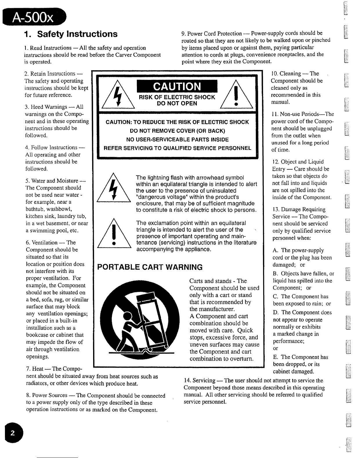
PORTABLE CART WARNING
Carts
and
stands
..
The
Component should
be
used
only with a cart
or
stand
that
is
recommended by
the
manufacturer.
A Component and cart
combination should
be
moved with care. Quick
stopSt
excessive force, and
uneven
surfaces
may
cause
the Component and cart
combination to overturn.
nent should be situated away from heat sources such
as
14.
Servicing -The user should not attempt
to
service the
radiators} or
other
devices which produce heat. Component beyond those means described
in
this
operating
8. Power Sources -
The
Component
should
be
connected manual. All other servicing should
be
referred
to
qualified
to
a
po
wer supply only
of
the
type described
in
these service personneL
operation instructions or as
marked
on
the
Component
It

15.
To
prevent electric shockt
do
not use this polarized plug
with
an
extension
cord,
receptacle
or
other
outlet
unless the
blades can be
fully
inserted to prevent blade exposure.
Pour preevenir les chocs electriques ne pas utiliser cette
fiche polarisee avec
un
pro}ongateur, un prise de courant
ou
un
e autre sortie
de
courant,
sau
f
si
Ies
1ames
peu
ven
t
etre inserees afond sans laisser aucune pariie adecouvert.
16. Grounding
or
Polarization
-..
Precautions should
be
taken
so
that the grounding or polarization means ofthe
Component is not defeated.
17.
Intern
a1lExternal
Voltage
Selectors -Internal or
external line voltage selector switches, if
any,
should only
be
reset and re-equipped
with
a proper plug
for
alternate
vol
tage
by
a qualified service technician.
See
an
Author
..
ized Carver Dealer for
more
information.
<.
.'.'
_..
oX
~,::.::;:
.
~'.."
~.
~:.':
I..
..
18.
Attachment Plugs for Alternate
Line
Voltage (Dual
voltage models only) -
See
your Authorized Carver
• I
~.:
••
••••
•••
"
. '"
'A';o
-"5""0"0':
:',
",",~'o:;~
Dealer for information on the attachlnent plug for alternate
voltage use.
This
pertains
to
dual-voltage units
only.
This apparatus does not exceed the Class A/Class B
(whichever
is
applicable) limits for radio
noise
emissions
from digital apparatus as set
out
in the radio interference
regulations of
the
Canadian Department of
Communica-
tions.
ATTENTION -Le present appareil numerique
n1emet
pas
de bruits radioelectriques depassant las limites applicables
aux
appareils nunleriques
de
class
Aide class B (selon
Ie
cas) prescrites dans
Ie
reglement sur
Ie
brouillage
radio61ectrique edicte par les ministere des communications
du Canada.
WARNING
-
TO
REDUCE
THE
RISK
OF
FIRE
OR
ELECTRIC
SHOCK,
DO NOT EXPOSE THIS APPLIANCE TO RAIN OR MOISTURE.
CAUTION:
TO
PREVENT
ELECTRIC
SHOCK,
MATCH
WIDE
BLADE
OF PLUG
TO
WIDE
SLOT,
FULLY
INSERT.
ATTENTION:
POUR
EVITER
LES CHOCS
ELECTRIQUES,
INTRO-
DUIRE LA
LAME
LA PLVS LARGE
DE
LA FICHE
DANS
LA BORNE
CORRESPONDANTE
DE
LA
PRISE
ET
POUSSER
JUSQU'
AU
FOND.
Contents
1. Safety Instructions
~
+.It
••••••••••
t t
••••••••
~
•••••••••••.•••••••••••
2
2.
Prelude , 4
3.
Fea,tures
and
Specifications 61' , , ,
••
4.
Unpacking
and
Paperwork 7
5.
Installation , 8
l
..
ocation
and
General Precautions 8
Handle Removal
""
..
~
8
AC
Power Considerations , 9
Connection
Tips
~
9
Rear Panel
Connections
and
Controls
9n
6.
Operation
~ ~
, 10
Front
Panel Features 10
System
Configurations
12
A qUick
note
on
input/output
levels " 17
Amp-to.Preamp
Connections
17
Amp-to-Speaker
Connections
,
17
Wiring
.,
,
"'
17
Hook-up
~
17
Stereo Operation
~
18
Mono
Operation
~
"
18
Amplifier
Protection
19t
Speaker
Protection
19
7..
In
Case
of
Difficulty 21t
8. Care
and
Service Assistance , ,
~
23t e

..
·:'···;'·/;A"·'"
':~.:',
'.s'"
0'"
0·'
.
'.
'<.~.:.:;",.'
".~'~~"'-:.
"..
'.
x .
I
••
-:
••••
: I •
~:
;
•••
_ I ' - •
~",
_
-.,
2. Prelude
Your
new
Carver
Magnified
Current™
THX
Power
Amplifier carries
with
it a
heritage of over 15 years
of
audio
research,
development
and
design
refinements.
Carver engineers
make
use
of
the
latest
advances
in
electronics
ma·nufacturing
techniques
to
provide
state
..
of-the-art
high-value audio
products
which
empha-
size
innovative
technologies
and
features
at
an
affordable price.
An
American
electronics
innovator
based
in
the
Pacific Northwest,
Carver
began
in
the
early 80s
with
a series
of
product
successes
such
as
the
C-4000
preamplifier
with
Auto-Correlator™
and
Sonic
Holography'11vi,
the
TX-l1
tuner
with
ACCDTM
(Asymmetrical
Charge-Coupled
Detector)
and
the
M-l.S
stereo
power
amplifier,
one
of
the
most
powerful ampli-
fiers available
at
tile
time
for
home
hi
..
fi
uset
.As
technology
has
evolvedt so have
Carver's products.
In
fact, a
number
of
audio technologies an·d features consid-
ered
standard
today-
including
surround-
sound
and
advanced
signal
processing-
had
their
first successful
consumer
appli
w
cations
in
a Carver component! Many
Carver
products
are
now
considered
"clas-
sics",
and
most
are still
in
use
with
their
original
owners
who
routinely upgrade
their Carver-based systems
rather
than
replace
them.
As
it
has
since
our
company!s
beginning,
the
Carver
name
remains
synonymous
with
leading
edge
technology
expressed
in
audio
compo-
nents
that
never
become
obsolete.
At Carvers
technology
is
regarded
as
a
tool
used for
one
purpose:
to
advance
the
science
of
reproducing
sound
in
the
home. Every
Carver
employee
has
this
common
goal,
from
our
CEO
and
Board
of
Directors,
our
Engineering,
Sales
and
Marketing,
Accounting
and
Finance,
Customer
Service
and
Technical
SUPJ?ort
Staff
to
the
Manufacturing
and
QualIty
Control
people
who
actually
put
the
products
together
here
in
Lynnwood,
Washington.
We love
home
entertain-
ment.
The
vigilant
pursuit
of
I?roviding
0,
quality
and
reliable
products
aImed
at
reproducing
audio
with
absolute
accuracy
-
whether
it
be
from
a treasured
I.,P
vinyl
recording
or
the
digital
formats
of
tomor-
row
-
is
our
corporate
vision.
To
this end,
the
A-SOOx
was developed
with
a
number
of
important design
fea
..
tures
and
goals
in
mind.
A power
ampli-
fier
has
only
one
job,
but
a
very
important
one:
amplifying
the
audio
signal
without
being
disturbed by
the
loudspeaker
load.
Ideally,
the
signal
coming
out of an ampli-
fier
should
be
iderttical
in
every
way
ex-
cept
magnitude
to
the
signal
that
went
into
itt
In
realitr'
there
are subtle ways
in
which
the
signa
can
be
changed
by
an
amplifier,
which
are
described by
measure-
ments
such
as
THD, noise,
DC
offset,
crosstalk
and
phase
shift. All
these
techni
..
cal
terms
boil
dow.n
to
one
thing
-
the
signal
has
been
changed
(distorted)
in
some
way
from
its original
form
by
the
amplifier. I
There
are a
number
of
ways
to
mini-
mize
this
distortion.
One
of
the
most
effective
and
efficient is
to
minimize
the
signal
path~
While
that
may
sound
simpleJ
it
is
actually
very
difficult
to
achieve.
OUf
engineers
went
to
great
lengths
to
shorten
the
signal
path
(pun
intended!)
as
much
as
technology
and
physics allow. A
short
signal
path
pre-
vents
corruption
of
the
signal from
the
effects
of
EMI, strayfield
magnetic
radia-
tion
and
cumulative
reactance
in
the
critical signal
conductors.
l~he
result
is
a
much
cleaner
(and
very
nearly
perfect)
reproduction
of
the
signal
at
the
amplifier's
output.
The
A-SOOx
is
rated
conservatively at
250
watts
per
channel
into
8
ohms
and
delivers
over
400
watts
per
channel
into
4
ohms.
It
also
has
the
flexibility
and
power
®
(-
r:':,'·'
L._
L
I.
L
1,."
1'.:
....
:.
L
I·:·:::··
J
I'·
L
k
L

--
reserves
to
become
an
800
watt+
bridged
mono amplifier
when
even
higher
power
levels are needed. This is
an
enormous
am'ount
of
power,
made
possible through
the
development
of
a
new
multi·state
hybrid power amRlifier design
we
call
Magnifled
Current
. It uses
two
160
amp
peak current
power
MOSFETs
per
channel,
with nanosecond sWitching speed
to
assign twice
the
continuous
voltage
to
the
·
output
stage
when
high
voltages are re-
quired}
or
more
than
twice
the
continuous
Ctlrrent
when
higher
current is needed.
This maximizes
both
the
voltage
and
current
capability (peak
or
continuous)
available for any
loudspeaker
load;
even
thos.e
that
have
a
substantial
reactive
component
that is difficult for conven-
tional
amplifiers
to
drive.
As
a result
of
this
difficulty
in
driving
demanding
loudspeaker loads,
conven-
tional
amp1ifiers
use
stabilizing
inductors
on
the
output
of
the
amplifier
to
keep
the
amplifier from oscillating
and
even
self-
destructing.
Unfortunately,
these
in·due-
tors also cause low
damping
at
high
fre-
quencies
which
can
create
high
frequency
coloration.
Carver
has
developed
Total
Direct
Coupling™
(TDC)
to
combat
this
problem.
TDC
means
that
the
output
circuitry is
directly
connected
to.
the
loudspeaker
without
the
usual
stabilizin~
inductor
networks
between
the
amplIfier
output
and the loudspeaker termInals. Due
to
the
wide
open
loop
bandwidth,
ideal stability
and
load
immunity
of
the
new
Carver
amplifier module, the traditional sound
altering Ustability
bandaids"
of
conven-
tional
amplifiers are
no
longer
necessary.
This
not
only
cre'ates
a totally stable power
amplifier
into
all speaker loads,
it
also
provides
high
damping
factor
at
all
frequencies-
not
just
i.n
the
bass region.
lUCASFllM
.
.'
··A-500x·:
That
means
full
control
in
th'e bass,
midrange and
high
frequencies.
No
more
harsh
or
rolled
off
highs, just
pure
and
natural clarity from top to bottom.
In
addition
to
new
audio
technologyj
Carver engineers also designed the
A-500x
to
set
new
stand~rds
in
reliability
and
value. The
A-SOOx
makes full
use
of
their
modular
d'esign
philosophy
and
open-
frame
architecture
for efficient
and
cost
...
effective
assembly_
This
has
the
added
benefit
of
providIng
superior
channel
isolation, eliminating the
detrimental
effects
of
interchannel
crosstalk.
The
amplifier's
enclosure
is·
designed
to
pro-
vide open air access
to
the
heatsinks. This
affords
more
efficient dissipation of
heat
away from
the
triple-diffused
planar
high-
current
output
devices,
which
results
in
greater reliability
and
longevity
of
the
amplifier.
The
THX logo
on
the
front
panel
of
the
Carver
A-SOOx
is
another
important
fea-
ture
of
the
amplifier. THX certification
means
that
the
A-SOOx
meets
a set of strict
performance
standards
which
ensure
that
the
soundtrack's
reproduction
is
faithful
to
the
director's
intent~
The
Carver
A
..
500x
can
be
used
with
other
THX
certi-
fied
audio
equipment
to
create a
true
Home
TH.X
Audio System.
Other
features are
included
to
provide
convenience
and
flexibility
such
as
vari
...
able
input
sensitivity controls, removable
handles
and
front
panel
analog
meters
with
two
sensitivity settings.
The Carver
A-SOOx
was designed
and
manufactured
by
people
with
a lifetime
commitment
to
providing
the
world's
finest
components
for
sound
reproduction
and
home
entertainment.
Thanks
for
placing
your
confidence
in
Carver. We
know
your
new
amplifier will provide
many
years
of
listening
enjoyment.
If you have
access
to
the
Internet,
you
can
check
out
the
full line
of
Carver
products
and
company
an
..
nouncements
·on
our
World Wide·
Web page (http://www.carver.com).

o.:':'·A··"':··"S:···:'·O'O·
'.-.:
....
I I
•.
~
:.
, .
".~:
.
~.
I".
.
~-
,"
.:
..
,.. > .....
;.,
..
' :
·X':
'.
~
.,.'.,.,
::
~
\.'
,... ,'
r
~;
tr
3. Features and Specifications
~
A-500x Special Features [
0 250 watts
per
channel
into
8
ohms
o Fully-complementary
differential
cirCllitry
400 watts
per
channel
into
4
ohms
using low-noise,
high
speed transistors
t~;~::'
750
watts
per
channel
into
2
ohms
throughout
lL
(IHF
dynamic
power) o DC Servo correction using new Texas
800
watts
bridged
mono
into 8
ohms
Instrument
Excalibur™
operating
point
":,".','
a Certified
by
Lucasfilm Ltd. for use
in
controller 1
;~.
Home
THX Audio Systems
~
a Double-stage
ground
isolation system
o Magnified
Current™
technology
for in- prevents
gro~nd
loops and
RF
inte-rference
creased voltage
and
current
capability o Triple-diffused
planar
high-current
otttput
l~
L..
o Total Direct Coupling™ for
high
damping
devices
with
a
cOlnbined
output
safe
factor
at
all frequencies
operating
capability
of
1000
watts
o Each channel
protected
by: o Dual
analog
lighted
meters
with
range l
Individual
fusing
selection
switch
DC fault sense o
Meter
light
On/Off
switch
t:.
Shofted-load sense
Excess
temperature
sense o
Gold-plated
RCA
input
jacks
~:"
Powerwon delay o
International
safety
compliant
binding
o Minimal signal
path
design,
with
on-card posts
k,·
t
I/O
connectors
eliminating
internal
inter- o Individual calibrated level trim controls for
connect
cables
each
channel
'i-:;::."
0 Precision
passive
components used
in
all o Removable
handles
for
placement
in
17"
rf~
'if...
critical
signal
paths
(no
electrolytic
capaci
w wide
cabinet
space (with
trim
end
caps)
tors
in
signal
path)
o Made
in
USA
l
Sp'ecifications
!~""
fe',
Power
Output:
E,
L
Stereo operation:
f~,',
,
Power
FTC
20Hz-20kHz, 8 ohm
250
watts per channel with < 0.08%
THD
Damping Factor: > 150 l
400 watts per channel into 4 ohms
(20
to 20kHz) v
750 watts per channel into 2 ohms
t~;~,.
(IHF
dynamic power)
8.
Input Impedance: 47 kohms
Bridged mono operation:
r:
800
watts into 8 ohms Sensitivity:
~:::.
Per
THX
standard: L
}';"
Dynamic Headroom: 1.0V rms input for 1
DOW
output into 8 ohms
> 1.0dB @ 8 ohms both channels
drive'n
1.58V
rms
for rated power into 8
ohms
@1
kHz
t:::,
I
Frequency Response: 20
Hz
to
20
kHz Gain: 29.0 dB (+/-
O.5dB)
(+0,-0.2 dB)
F'
k
Input-to-Output
Phase: 0°
(±100)
__
Separation: >70
dB
@ 1kHz

1M
Distortion:
SMPTE
<
0.03%
CCIF <
O~01
%
THO: < 0.08%
Signal-to-Noise
Ratio: > 117
dB
A-weighted, referenced to rated power
> 93
dBW
A-weighted, referenced
to
1W
Power Consumption:
50W
at
idle
330W
with
musical
program
880W at full
power
into
8 Q (continuous)
Power
Requirements:
120VAC/60Hz
(USA
and
·Canada)
Other voltages as required
for
export
Display: 2 Analog Meters;
OdS
= 250
watts
into 8 n
or
25
watts
into
an
(x10 range)
Size
(H
x W x
D):
5.75'1
x 19·· X
18.8
11
146mm
x 483mm x
478mm
with
handles
5.75" x17
1f
x 17.8"
146mm
x
432mm
x
452mm
without
handles
Net Weight:
29
Ibs. (13.2 kgs)
Shipping
Weight: 34
Ib·s.
(15.4
kgs)
Features
and
specifications
are
subject
to
change
without
notice.
..
<
A~5()Ox·<'
, .
I.":
,'-
4. Unpacking and
Paperwork
Carefully
unpack
your
A-SOOx
and
keep
the
original carton
and
packin'g materials
for
future
moving,
shipment
or
long-term
storage~
After
opening
the
box, please check for
any
visible signs
of
damage
that
were
not
apparent
from
the
outside
of
the
box.
If you do encoun-
ter what appears
to
be concealed
damage,
please
consult
your
Carver Dealer before
proceeding
to
further
unpack
or
install
the
unit.
Important
Paperwork
Make
sure
to
save
your
sales
receipt.
Your receipt is
extremely
important
to
estabw
lish
the
duration
of
your
Limited Warranty}
and
for insurance purposes. Next,
make
a
note
of
the
serial
number
which
is located
on
the
back
of
the
amplifier. Record
it
in
the
space
provided below for convenient reference
..
Model: A-500x
Serial
Number:
_
Purchased at:
----0-..----
Date: _
Finally,
take
a
moment
to
fill
out
the
Cus-
tomer
Registration
Card
packed
with
the
amplifier
and
return
it
to
Carver
..
This allows
us
to
keep you
informed
of
new
products
and
technologies
as
they
become
available.
e

--
L
1"-
~
• • L
'.;
,<
"0"0'
".'
\<::,!A7$
.
••.....•
~
•.....
l::~;:,,
t-
L...;.,;,
5.
Installation
Location and General
Precautions
Observe
the
following
precautions
when
choosing a
location
for
the
A-SOOx:
o Do
not
expose
the
unit
to
rain
or
moisture.
o Protect
from
prolonged
exposure
to
direct
sunlight.
o Avoid excessive
exposure
to
extreme
cold
or
dust.
o Do
not
place heavy
objects
on
the
unit.
000
not
place
magnetic
storage
media
suel1 as
audio
or
video
tapes
near
the
amplifier. All
power
amplifiers
con-
tain
transformers
that
are
surrounded
by
a
fluctuating
magnetic
field
which
can
erase
magnetic
tapes
(or
floppy disks).
a Protect
from
heat
and
allow
adequate
ventilation.
Place
away
from
direct
sources
of
heat,
such
as
heating
vents
and
radiators. All
compo-
nents
produce
some
heat
during
operation!
so
make
sure
that
the
ventilation
holes
are
not
covered
and
that
air is
allowed
to
circulate
freely
behind,
beside
and
above
the
unit.
Excessive
heat
is
the
single greatest
source
of
both
short-term
and
long-term
component
failure.
A)
Remove Handles
-----~
B) Install Spacers
The
amplifier
can
be
placed
in
an
equip-
ment
rack
or
cabinet
Wllicll
has
adequate
ventilationQ
If
your shelves
do
not
have
open
backs,
make
sure
there
are
vent
holes
in
them.
The
situation
)'0U
want
to
avoid is
placing
your
power
amplifier
in
a sealed cubby hole.
That
creates a static air space
where
tempera-
tures
can
rise quickly.
o Allow
at
least 3
inches
of
air space above
the
unit}
and
at
least
linch
on
either
side.
o
Do
NOT
place
the
amplifier
on
carpeting
or
any surface
that
might
tend
to
block its
ventilation
slots
from
air
circulation.
o If possible,
place
the
A-SOOx
in
its
own
shelf space, i
separate
from
other
compo-
l-:-:
5,-_,
nents.
L-
o If a fluid or foreign object i
should
enter
the
unit
l discon-
1.
nect
the
power
plllg
and
l
contact
an
authorized
dealer
or
service center.
Do
not
pull
out
the
plug
by
pulling
on
the
cord; grasp
the
pllig
firmly.
-;
1L--
Handle Removal
l-
t
The A
..
SOOx
is
shipped
with
tIle
h.anciles
installed.
t-
To
remove
the
handles, use a
!'._:
t:
..
>
Phillips screvvdriver to
re~
L::.::..
move
the
three
screws
on
each side of
the
chassis just
1-;-,-
j
behind
the
front
panel.
Remove
the
handles
and
L-
install
the
spacers
provided
as
1--
shown
in
Figure
4.
Reinstall i
L
the
three
screws
on
each
side
I~
of
the
chassis
to
secure
the
spacers
in
place. L
Store
the
handles
in
a
safe place for future use.
L-..--
Figure
4.
Handle Removal
1-;.-

I I I
,.
.
·A-500x··
.•
AC
Power
Considerations
a
component's
power cord gets
too
close to a
hook-up
cable
..
Ensure
that
the
A-SOOx
is
plugged
into
an
o Choose reliable
hook-up
cables (also called
outlet
capable
of
supplying
the
correct
voltage interconnects, patch cords or
RCA
cables).
specified for your
model
and
enough
current
There are lots
of
different grades
of
hook-up
to
allow full-power
operation
of
all
the
cables. You
can
pay
more
than
$50 per foot
components
connected
to
it. for
some
of
them!
Whether
or
not
you
hear
Although
the
A-SOOx
can draw
momentary
an
improvement
in
sound
quality
with
u
au
-
peak's
of
1400
watts
or
more,
with
musical
diophile"
interconnects is
up
to
your
own
programs
the
amplifier will typically require ears. However, really
CHEAP
or
old connec-
an
average
of
330
watts
or
less.
tion
cables
can
sometimes
DIS-connect
them-
selves inside}
causing
hum
or
a loss
of
sound
in
one
or
both
channels. Before
you
send a
component
in
for service, swap hook-up
Connecti·on
Tips
• cables
to
see if
they're
the
cu.lprit.
Before
launching
into
the
actual cable-
connection
frenzy
of
setting up your new
system, consider
the
following· tips. Rear Panel C·onnectio·ns
a·nd
o Make sure all compone.nts are
OFF
before Contro·ls
making
any
connections. It's a
good
idea
to
plug
in
Y6>ur
.\C power cord last
to
avoid
1.
STEREO/MONO
Switch
accidentally
turning
on
the
unit
while
For
normal
stereo
operation
J
this
switch
installing.
should
remain
in
the
ST'EREO position. (This
o Make sure
that
"left
is
hooked
to
left
and
model
is THX certified for use
in
stereo
mode
right is
hooked
to
right"
at
each
connection.
only.) By
switching
it
to
the
mono
position,
The
obvious
way
to
assure
this
is
to
assign
one
you may use
the
A-SOOx
as a 800 watt (at 8
hook-up
cord
plug
color
to
left
and
the
other
ohms)
mono
amplifier. See page
18
for
more
to right. Generally
RED
is
used
to
signify
information
on
input/o~tput
connections
in
RIGHT. White,
grey
or
black
then
represents
mono
operation~
left.
o
Whenever
possi};lle,
keep
power
cords away 2. LEVEL
Controls
from signal cables
(inputs
to
CD player, tape These calibrated
controls
are
used
to
adjust
deck, etc.)
to
prevent
hum.
While
hum
is less
the
input
sensitivity of each
channel.
When
of
a
problem
today
than
it was
in
the
past,
using the
A-SOOx
in
a
THX
system, leave
these
noise can still find its
way
into
your
system if
controls
in
the
fully clockwise
position.
5
".....
__
..
,
Iii
@
(ii}:
©
MO""~"'·O
-eit
..
.
O-M'e.
H,e_·5
+ -....01<
.o.CK
8
IGHT
LEFT
0.
*
ON'4
LIlP'T
IMPV'
KTIIWrrCHTO
M(ltK)
'HANNEL
CHANNEL
ifj-
WARNeKO
"'Qf~llolIR.\'l~f1lOi't.l'l
....
litA.
."U,iI'iEII
eOl'tNl!CnQf&
.....
RA
....
IIlllnurH'*'
....
1IBi+I1~"
....
I.I.CMkIiIl-W.
~lIIf'O'l.~
196912300051
...
'A"'lIA'IIMpnll,.....~.lKQOI5IlIUll:l.Ml4i
(1)
(f)
~""'lIMICftlil'Qt4(lTICIloMMiIt.
li'''';::'NOrtFii'~
IG) ,!SEEu · e
Figure
5.
A-500x Rear Panel View

L
..
·:,A-500)(···
~:
~
'"
, . -"
....
~
.
Each
channel
will
then
provide a
sensitivity
of
1V
Input
=
100
watts
Output
that
is required
for a
Home
THX
Audio
System.
Individual
channel
adjustments are
then
made
using
the
balance
controls
provided
on
the
THX con-
troller.
For
non-THX systems, the
LEVEL
controls on
the
A-SOOx
can
be
used
to
adjust
and
fine
tune
the
balance
between
the
various channels
in
your
surround
sound
system.
Note:
For
TUX
Audio
Systems,
leave
the
LEVEL
controls
on
the
A
..
SOOx
in
their
fully
cloc-kwise
position
3.
LEFf
and
RIGHT
INPUT
Connecto-rs
These
line
level
input
RCA
jacks
connect
to
the
audio
output
jacks
of
your
preamplifier
or
surround
sound
decode-r. See
page
14 for
the
recommended
nlethod
of
connecting
a sur-
round
sound
system
to
the
A-SOOx.
4.
LEFT
and
RIGHT
SPEAKER
Outputs
These
international
safety approved
bind~
ing
posts are used
to
connect
the
loudspeakers
to
the
amplifier
outputs.
Please check
the
Arnp
..
to-Speaker
Connection
instructions
on
page 17 for
information
on
cable selection
and
connections
to
your loudspeakers.
tl:-n
Note: The
output
of
the
A-SOOx
can
develop
hazardous
voltages. Care
should
be
taken
in
connecting
the
speakers
to
prevent
electric shock
or
damage
to
the
amplifier.
Turn
tl1e
A-SOOx
OFF before
making
any
change
to
speaker
wiring
or
when
connecting
the
unit
to
another
component.
5.
AC
Linecord
Connect
to
a
properly
configured outlet
providing
the
line
voltage
specified
for
your
model.
16
Note: We
recommend
that
you
do
not
use
the
convenienc~
outlets
on
the
back
of
a
preamplifier as
the
AC
power
source for
the
A-SOOx.
Most preamplifier convenience
outlets are
not
able
to
handle
the
turn-on
surge
current
and
power
reqUirements of
the
A-SOOx.
Be
sure to check
the
preamplifier's
recommendations
and
convenience outlet
6.
Operation
Front Panel Features
6.
POWER
Switch
When
the
A-SOOx
is first
turned
on,
the
indicating
LED
illuminates green (6a)
and
the
outptlts will
be
muted
for about four
seconds
to
allow
the
amplifier
to
stabilize" This
delay
circuit helps
prevent
speaker-damaging
thumps
when
powering
up. We suggest
you
turn
on
the
amplifier
AFTER
you
have
turned
on
your
signal
source
equipment
(preampli-
fier, CD player, tuner, etc.).
Also
make sure
that
a
loud
signal
source
is
not playing
when
the
amplifier is first
turned
on, or you'll be
in
for a
big
surprise
when
the
muting
circuit
disengages.
7.
Power
Meters
The
A-SOOx
features
ballistically-weighted
power meters
that
are calibrated
in
decibels.
The
main
dB
scale
has
a
top
value of
+3dB
,
with
OdB
equal
to
the
maximum
rated
con-
tinuous
power
(into
8
ohms)
of
250
watts
per
channeL
The
meter
ballistics
include
a fixed
amount
of
overshoot that's standard for
tIl-is
type
of
metering.
Salon
some
musical
material,
the
meter
will
often
move
past
the
OdB
level
and
o~
to
+3dB
(when
played
VERY
loud).
At
the
same time,
on
some
musical
material
the
amplifier
could
be
reaching
its
maximum
power
even
though
the
meters
aren
l t reaching
full scale.
This
is because
the
meters are
indicating
an
average
of
the
power
output
o-ver
time.
Momentary
musical
peaks
can
drive
the
amplifier
to
its maximum
output
for
brief
periods,
faster
than
tile
meter
can
respond.
~
_i
l--:_
L_
t
L
r
..
t?
i
L-
t
n~
L
L~
~-~
l-.
L.....
'!
(
~:
~~
L
L
t~
(:>-'-
~
-!_--
~-~-
.
.
~:
L
~,
L.c.
;',---
e
power
ratings
before
attempting
to
connect
the
A-SOOx
to
a
preamplifier's
convenience
outlet.

Because different musical material reacts
differently
with
the
ballistics
of
the
meterI
the
best way to tell
whether
the
amplifier
is
over-
loading is simply
to
listen.
If
the
sound
becomes distorted
on
musical peaks at
the
same time
the
meter
is
(J
pegging
II
I
you
have
probably exhausted.
the
A-SOOx/s
power
re
..
serves. If this
should
occur, you
should
re"
duce
the
volume
level to
prevent
the
A-SOOx's
overload protection
circuit
from
being acti-
vated.
8.
METER
LIGHT
Switch
This
button
will
turn
the
meter
lights ON
and
OFF.
This allows you
to
improve
the
viewing
of
the
meters} depending
011
the
light
level in your listening room.
9.
METER
RANGE
Switch
When
pushed
in;
analog
meter
sensitivity
will be increased ten-fold
(OdB
=
2S
watts). If
you are
funning
the
A·500x
at
louder
volume
levels,
do
not
activate
this
switch. This switch
will
only
affect
the
scale of
the
meters, it does
not
change the
output
pow.er
in
any
way.
lflCl'WUI
•e
ItOW!A
·A-500x.·'
8 9
A~500x
Magn.,le-d Current Power Ampll1io
~
c:::>
c:::>
Figure
6.
A
...
500x Front Panel View e

'.'::.·A
..
SOOx·
I
~
:
•••...
..'
I _
••
~
,
SYSTEM CONFIGURATIONS 1
i....
The
followil1g pages
contain
drawings of typical connections
that
you
might
make
in
your
installation~
Tllese drawings
demonstrate
how
the
inputs
and
outputs
on
the
rear panel of
the
A-SOOx
are
interconnected
with
other
audio
components. l
Stereo/Mono
Switch
set
to
STEREO
position.
.~_.~"""''''._~''''''''_._
~
................
-'\.
"'!1hi
Fl
r9
il(±)
l=J
l=J
v&
o
~~~
!t~
'i~!
ii~
III
dl'h
~1.I;
~llii
lUI)
mIl
nnn
""
~·ffi
~~.~
.?:jj
~d
o
~
\WJ
€J¥O'--@4i)·
I'
S
r.!>®
if.fF.."v..
\!f
'8 •
u
~~
0
10
® 8@
I)
1
+1
£
~Q9
I
'j?
~-!
~~.~
~
....
~"I;JI,W.r;
__
..,.
........
....-..ol
I
@) I
Id'MIR.~
.A
I I
I;
II
;
L
~
I~
~
Il
tL
hr
Ui
I!
Ii
II
@ L
J
~j
HI
l~
II
l'
~
j
ill
§~
s;
l-~
Ii
5
h~
e
i_
g
J~@
1:1_
G)
rn
..J
UJ
~~
<!'<
_%
C:U
~
+
Ile
..
<i
_1'iIJ(0
111
!I
i
III
§I
i~al0A
Ii
0~'
~
r-@M+
~
. e
L
e
9-@l
~
@
@)-i
®
:@
I)
li
~
L-@
<I'
1
®
~0·
a
L.@f).
i~C
rv
e
.
~§
..
@
e P'igure
7..
Normal
Stereo
Operation

t.»
iii
z
l!:~
w-x
...10
~.0
•.
@ct
6>
,
11
fl
II·
i
I!
I
I:
II~
II
II
Ii
tit
~
Ix!
I
e
;i
I I I -
..
~
II!
[if
z
§~
I; .
@.
0.
;
..
(!)
._1
t 0
r-@
I>
)
4>.,~
0
r<!>}i'li
~0
••
'-@Ii>i
l
llIlllR
lr~
_III.
[dr:J
!i®
vi
H.
iii
'II
I'
.•....
A~5QOx.~~··':.
I"nstallation Notes:
Two
A-500x amplifiers operating in bridged
mono
configuration
..
Set
Stereo/Mono
Switch
to
MO"NO
position.
Connect
the
Red LEFT SPEAKER Binding
Post
to
the
positive
(+)
speaker connection.
Connect
the
Red RIGHT SPEAKER Binding
Post
to
the negative (-) speaker connection.
Note: Use a speaker rated at 4 ohms
or
more
when
operat~ng
in
bridged
mono mode. Use
the
LEFT
LEVEL
control
to
adjustthe level
..
(W
~-_....-._
..
_----_.
(-----
•• i
I f
t
i~i
H~
..
iiliJ
..
..
~
(f)
<f
ill"fi
Hi
l
~
II"!
fn,i
ilh
j
lIn
t
d~!
A
........
1 e
~
~w
~-
__
'
.....
,
••
_."
....
...."..,""~
..
".~
~
~!~l
•
~
~~"-_-.r.-=o
la
....
=-
...............
~I
U0
$,)'
rI
;"
~
g
(f).1
I
~1g]
~
4->0.
I
I~
j @
rn
I
~
® i
'i-I
®
;-!@f)
lief)
II
!0
! (!)0(i) •
tV
-0
fm'
d)
raJ
I
~
'!-.
~
..
-
1
11
)
~
i~
hi
_
~
Iii
1
11
M _
19
~
"---_
..
,'~,
....
__
......
_--,
......
-_._
.....
__
._-_.J
Figure
8.
Bridged
Mono
Operation fit
..
~_.'-''''',y

W9l-sAS
punoS puno.uns lauuellO
~
'S J9le94.l
awoH
'6
9Jn6!:1
e
..
en
.c:.
..
OJ
:e
.
g,
"
ril
:0
22!
~o
z:!i
m
....
$
$
~I
~m~
~ll
I +
Ih
lJ
,..
m
1'1
!t
III
i
~I
&
'Ilfl
I
III
i'1sll
I
II
II
..
JI
;
~!
~O
z::t
z
....
,..
m
JJ
C5
~
,0
:B
'z
...,
~
i
il
III
III
if
1,
f71
0
II
II!
I,
'II
,llltl
l
I
00
·
...
~
....
..
m '
,
JJ.
,.
.~
,.'.'"
...
r
m
.''',
::}
.,.,
:0
- 0 '
..
:2
-i
"

-"
~
··.A-500x:\)
"
~
•
.':'
•
~
• I I
...
"
01
Installation Notes:
Bi-wiring involves connecting one cable
to
the high frequency input and one cable
to
the
low
frequency
input
of
the speaker
..
Both leads (from the same channel) are
attached
to
the
same
power
amplifier
outputterminal.
THIS CONNECTION REQUIRES
SEPARATE
HIGH
FREQUENCY
AND
LOW
FREQUENCY
INPUTS TO
THE
SPEAKER.
~
:
f)
~.
1
~
~~~.
~\
S I
..J
<c
I I t
1+
~
r!
III
~
.
bHd
i!$
"I
I~l
Ii'
iii
-«It
I(
<If
n~~
tIl
II-G>~
iliff
i
(i)1I
! I e
1
1
1
1
1
''ft,@~®
ll'l
l~@.
~UJl
! 0@.
~
i
\!J
--11
o
r<!) • 1
;
4~
~
••
til 0
'I
Hi>.
i
I
lu>0
•.
~
~0
rGJ0-
Ijl
~
'-(!)l'.8
I
q.-.
J:'\®Ql.
w
!I\!1~4ie
11'0.@0
•.
o @
f~~"1
$
~~
;lml
Hf
tir'·1
t~
!§
I
II~
I~
$
rn
t1l
I
._
..
_._-----~:::.:::.:::.::.~._)
J
~-Q
·
~
~
1
~~'
II
.
~
~
f
A~--l-I
---I
o « J I J
l+
Figure 10. Bi-Wired
Connection
to
Speakers
with
built-in
crossover •

,''',~:"A~500x
"
II'~.
~'"
• I •
••
: •
Installation Notes:
Bi-amplification requires separate
power
amplifiers (or
amplifier
tid
HJ
III
I r
~
!:i
!
<tt!>
~
I
-r--rt'~~-4-1
---11.
-
~
~
.
~
~
I I f 1+
1'1
II,
f:]f:]I!e
~.
·~u
U~'i
11~1
;
II
@
(f)
I
r-Ci}~{+
@
L..:$_
~@I
i@fi)-Il
@ t
~e.·
11
r@e,
Hi($)-
,I
'j
@
I @
1I@".
e
I~~I
I (f)
rn
$-
.
~
~
I.
f)
~J
J
1+
J r
0ct>
L·
t·:'
channels)
for
the
high
frequency
~
~:.:
:
L.
and
for
the
low
frequency
inputs
to
the
speakers. Use a
V-cord
be-
tween each preamplifier
output
(L
&
R)
and
the
inputs
to
the
two
amplifier channels.
<41
In
its purest sense,
this
is
not
true
"I
!,II
I I
bi-amplification,.
as
the
power
'1
"1
amplifiers are still reproducing
the
lit
r,
1
full audio spectrum. The speaker's 1
Ubi
buitt·in crossover splits the signal
~
into the
low
and
hi.gh
frequencies. r<;) •
THIS CONNECTION
REQUIRES
SEPARATE
HIGH
FREQUENCY
'I
o
AND
LOW
FREQUENCY INPUTS
~
I
TO
THE
SPEAKER.
@
t~
'!'
•
'fOll@~.
<::>
~,t;\.
~
\:I
II
1\J'
r.'\
\!I
e Figure 11.
Bi-Amplified
Connection
to
Speakers
with.
built-in
crossover

::;·L~&~50Q~/.:::·:·
r_
-~
A qUick
note
on
input/output
levels
Input and
output
levels
for
audio equipment
are
usually divided
into
three categories.
Phono Level: This is a very low level signal
that
comes
from
the
cartridge
of
your
turntable.
Because
of
its extremely low voltage,
it
has
a special
input
connection provided
on
most
preamplifiers
and
receivers. It provides extra gain
to
increase
the
signal,
as
well
as
reverse
RIAA
equalization
to
restore the flat
frequency response
that
was altered
by
the
equaliza-
tion used in making
phonogr~ph
records.
Only
a
turntable
should
be
connected
to
the
PHONO
input
jacks.
Line
Level.: This
is
the
signal level
that
COines
out
of
alnlost all audio
components
produced today, except
for
power amplifiers. It ranges from several hundred
111illivolts
to
several volts (AC). Your preamplifier
produces a line level signal
that
can
be connected to
the
input
of
the
A-SOOx.
Speaker
Level:
This is
the
signal level
that
comes
out
of the speaker output terminals
on
a
power
a.mplifier
or
receiver. It
can
range from several volts
to
several
tens
of volts (AC). Some
high
powered amplifiers can
reach voltage levels
approaching
that
present
on
a
household
AC
outlet! These
connections
should
only
be
made
to
a
speaker.,
"/
Amp
..
to-Preamp
Connections
The
A-SOOx
is
designed
to
be
compatible
with
virtually
any
quality
preamplifier,
pream-
plifier/tuner,
surround
sound
processor
or
THX controller. Use
standard
RCA-type
audio
cables
to
connect
the
RIGHT
and
LEFT
OUT-
PUTS
of
the
preamplifier
to
the
RIGHT
and
LEFT
INPUTS
on
the
rear
panel
of
the
A-SOOx.
It
might
help
to
refer
to
the
owner's
manual
for your
other
components
at
this
point.
System
hook-up
variations
are
shown
in
the
diagrams
on
pages 12
through
16.
Amp-to-Speaker
Connections
The
A-SOOx
is
designed
for use
with
any
type
of
loudspeaker, including
Home
THX-
certifie.d loudspeakers.
Wiring
Use
thick
wire
for speaker
connections.
V.our
Carver dealer can recommelld a brand
of
speaker cable. You
may
choose
11igh
quality,
oxygen-free
copper
(OFe) cable.
Or
common
uzip-cord"
from
a
hardware
store
can
be
employed
if
care
is
taken to
use
the
proper
gauge.
This
will
depend
on
the
distance
from
the
A-SOOx
and your speakers.
Use
the
follow-
ing chart
as
a
.guide:
Wi.re
Length
Gauge
of
Zip
Cord
Up
to
2S ft. 16 gauge
2S
to
40
ft~
14 gauge
40
to
60 ft. 12 gauge
60
to
100 ft. 10 gauge
The
greater
the
distance
between
your
A-SOOx
and
speakers,
the
larger
the
diameter
the
wire
should
be
(wire thickness specifica-
tions
or
Ugauges"
get
larger
as
the
wire gets
thinner;
thus
IO-gauge wire
is
thicker
than
16-gauge wire).
Hook-up
The
A-SOOx
speaker
terminals
are designed
to
accept bare wire or
standard
banana
plugs.
For
bare
wire
connections:
1) Strip
1/2
11
of
insulation
off
each
wire
and
make
sure
to
carefully twist all
the
fine
strands together. If even one
is
loose
and
can
touch
the
opposite
terminal,
a
short
circuit may result.
2)
Unscrew
the
binding
post
speaker termi-
nals
and
insert
the
wire (see Figure 12).
Tig-hten
the
connection
down
on
the
wire
(finger
tight
is fine;
DO
NOT use a
wrench!)o
3)
Although
the
speaker terminals are de-
signed
to
accept
up
to
10
gauge wire,
larger-gauge liaudiophile" speaker cables
may
be too thick
to
be
inserted
directly
into
the
speaker
terminals.
They
may
require
special
connections
or
adapters.
Consult
your Carver dealer for advice. •

·
>~:,'·~.A~50(jx
\;
[-
Figure 12. Bare Wire Connection
For
banana
plug
connections:
Banana plugs
can
be
attached
to
the
end
of
tIle speaker cable
and
plugged
directly
into
the
A-SOOx's
binding post sockets (see Figure
13). You
can
also
purchase
special speaker
cable
with
banana
connectors permanently
attached
or
molded
into
the
wire, This makes
connecting
and
disconnecting speakers
simple
and
quick.
M·ake sure
the
outer
terminal
is
completely screwed
down
(clockwise)
on
the
binding
post
when
using
banana
plugs
to
provide
maximum
electrical
contact.
h Note: The
binding
posts are deliberately
spaced 1" apart, so
that
double~banana
plugs
cannot
be used (3/4
11
spacing). This
is
to
comply
with
international
safety standards.
Stereo Operation
For stereo
operation
be sure
the
STEREO/
}:i'
MONO Switch
on
the
rear
panel
is
in
the
k
STEREO
position
..
Polarity
Loudspeakers
must
be
connected with
consistent
polarity for correct
phasing
be-
f-
r;~'
tween them. Incorrect phasing will do
no
L
physical
harm,
but
bass response will be
diminished.
The
key
is
to
make sure
that
both
f-,
speakers
connected
to
the
speaker terminals [
are hooked
up
the
same way.
1)
Connect
u_"
at
the
A-SOOx
speaker
outputs
t,~:
to
11_"
on
the
back
of
the
speaker,
and
"+"
at
the
A-SOOx
speaker
outputs
to
II
+"
on
t~
the
back
of
the
speaker.
t,
2)
Connect
the
A-SOOx
left speaker outputs
~.:.:-
to
the
left speaker inputs}
and
the
right ~L
A-SOOx
speaker outputs to
the
right l
c.
speaker
inputs.
If you're using special speaker
intercon
..
nects,
u+"
and
"_" will be identified. If
you're
using
plain
appliance-type zip cord,
the
two
l
~
"
conductors will
be
,differentiated
in
one
of
L
j'
1::.-.
several
ways.
They
may
be
different colors
(silver vs. gold),
One
may have
fine
grooves
on
its outside.
Or
one may have a piece of
1\
..
l
yarn
included
in
one
of
the
conductors
.(vis-
ible
after
you strip
off
the
insulation)t It
~:\::.
doesn't
matter
which
one
you decide
to
call t
"+/1
or
"_",
just
do
the
same
for
both
speakers.
1
I".
t·:'
L.
Mono Operation L
The
A-SOOx
will
provide
800 watts
of
power
into
8
ohms
when
used
in
mono
(bridged)
~
mode. See page 13 for
an
illustration
of
the
connections
to
be
made
in
mono
mode
of
operation.
,
Polarity
r
For
bridged-mono
operation,
you
will use
r'
I:
L
only
the
two
red
binding
posts.
The
LEFT
red
post is
the
u+IJ
side (hot, non-inverting)
and
L
~
the
RIGHT
red
post is
the
If_,I
side
(low, L
inverting).
" t'
Figure 13. Banana Plug Connection
j~
L
___
l

.
,A~50()(
:.':~:
To
operate
the
A-500x as a mon"o amplifier:
1. Set
the
STEREO/MONO
switch
on
the
rear
panel
to
the
MONO
position.
2. Connect
one
output
from
the
preamplifier
to
the
LEFT
input
jack
of
the
A-SOOx.
DO
NOT connect
anything
to
the
A-SOOx's
RIGHT input jack
during
mono
operation!
The
left
level control
will
now control tIre
totalgain
of
the amplifier.
3.
The
speaker leads for ONE CHANNEL
ONLY
must
be
connected
to
the
RED
TERMINALS
of
the
A-500x. The black
terminals
must
remain unconnected.
Attach
the
positive (+)
speaker
connection
to the
RED
LEFT
SPEAKER
binding
post.
Connect
the
negative (
..
) wire
to
the
RED
RIGHT
SPEAKF;R
binding
post.
Use a speaker
with
a
Y"tlng
of
4
ohms
or
more
for
mono
operation.
4. If
yOll
are
using
two
power
amplifiers
in
mono
to
create stereo,
repeat
these steps
for hooking
up
the
other channel.
f6J
Note:
In
bridged
mono
operation}
the
output
connections are actually a
balanced
output
configuration. This
means
that
neither
output
terminal
may
be
grounded
(both
are 'hot').
After
you've
hooked
u-p
the
speakers,
double-check your connections:
For stereo
operation,
be
sure
that
both
speak--
ers are
connected
in
the
same
way; positive
(+) speaker
terminal
to
positive (+) amplifier
terminal,
and
negative speaker
terminal
(-) to
negative
(-)
amplifier
terminal~
For
mono
operation
l
be
sure
that
the
positive
(+) speaker terminal
is
connected
to
the
LEFT
RED
amplifier
terminal,
and
the
negative (-)
speaker
terminal
to
the
RIGHT
R-ED
amplifier
terminal.
Amplifier Protection
F.using
All
fusing is
internal.
There
is
an
internal
line fuse
to
protect
the
amplifier
in
case
of
a
maj.or internal failure (not likely).
In
addi
..
tion,
each
channel
-has four
internal
fuses
to
protect the
individual
output
stages.
Warning:
These fuses are
not
user replace
..
able. If a fuse should blow, take
the
A-SOOx
to
a Carver
Authorized
Service
Center
for fuse
replacement and testing to determine the
reason
for
the
failure.
Current
Limiting
This
protection
mechanism safeguards
the
amplifier
against
very
low
speaker impedances
or
short circuits at
the
speaker
output
termi-
nals. If
the
amplifier is
driven
hard
into
a
low
impedance
speaker}
or
the
speaker wires
should
accidentally
short together, the
mut-
ing relays will switch off
and
the
output
of
the
amplifier will
be
disconnected.
After several
seconds
the
relays
will
turn
back
on
and
normal
operation will resume.
If the amplifier senses
that
the
high
current
situation
still exists,
the
relays will
switch
off
again.
If
this cycle
p-ersists,
check the
output
connections
and
wiring
to
make
sure
there
are
no shorts.
If
not,
it
may
become necessary
to
either reduce
the
volume
or
change
the
total
impedance of
the
speakers
connected
to
the
amplifier.
DC
Offset
In
the
unlikely
event
that
an
amplifier
channel should fail, a
DC
fault protection
circuit
prevents
a potentially destructive
amount
of
DC
from
damaging
the
speakers
by
immediately
turning
off
the
speaker relays.
Speaker Protection
If you are using speakers
that
do
not
have a
power rating high
enough
to
match
the
maximum
power
produced
by
the
A
..
500x/ we
recommend
that
you
install
in
...
line speaker
fuses
between
the
amplifier
and
your
speakers.
Use
the
fuse
value
recommended
by
the
speaker
manufacturer.
-'

,~(",~::·,~::~J~:;A.
:,:'.
~:5";
'::>"'0;',,
...
~
·'
...
·l
...
·::,·;
...
::.,
_:O~·:·:
.,:
:"
I''':''M
..
··
..
, .
X:·
..
:
..
,"
"<.,,'(~,
;:::.
;',
..
:~
_~:,
'.
':,
::
<v::'
~.'
'.'
If
you
can't
find
this
information,
the
following
formula
provides
a
good
rule-of-
thumb
to
determine
the
speaker fuse value
to
lise.
r::
~P/4R
where I =current
rating
of
fuse
in
amperes
P=maximum recommended
peak
power
handling
capability of
the
loudspeaker
in
watts
R = speaker
impedance
in
ohms
$
c..
:E
$
w
:J
..J
~
W
(f)
::>
u.
Use
a fast-acting
type
fuse, NOT a sio-blo type.
Install
the
in-line
fuseholder between
the
amplifierl s (+) speaker
terminal
and
the
speaker's
(+)
terminal.
See
Figure
14
for
a
graphical representation
of
the
above
formula.
k
a
h~
MAXIMUM
POWER
TO
SPEAKER
(WATT$)
[
Figure 14. Fuse Protection
for
Speakers
i.
1:,;
f,;:'
CD
i.
L~
This manual suits for next models
1
Table of contents
Other Carver Amplifier manuals

Carver
Carver PM-350 User manual

Carver
Carver pm125 User manual

Carver
Carver CV Series User manual

Carver
Carver Lightstar Direct User manual

Carver
Carver pm700 User manual

Carver
Carver M240 User manual

Carver
Carver pm1400 User manual

Carver
Carver Xi1850 User manual

Carver
Carver PM-1200 User manual

Carver
Carver PM-175 User manual

Carver
Carver PM-1201 User manual

Carver
Carver Xi1850 User manual

Carver
Carver pm1400 User manual

Carver
Carver PM-900 User manual

Carver
Carver ZR1000 User manual

Carver
Carver PM-300 User manual

Carver
Carver M400 User manual

Carver
Carver MSMP User manual

Carver
Carver PM-600 User manual

Carver
Carver pm1400 User manual