CARVIN LC24 User manual


LC24 SPECIFICATIONS:
Power input: DC12v-18V 500mA.
DMX output: 3pin XLR
MIDI output: 5 pin DIN
Audio Mic : internal
Audio input: RCA jack
Remote input: stereo 1/4"
Internal fuse: 0.5A 250V 5x20mm
Dimensions: 19x10.4x3.4 inch.
AC adapter: 120VAC – 12VDC 500mA
Weight: 10.6 lbs
MIDI IN SETTINGS
1.) Press and hold RECORD
2.) Press 1st FLASH KEY 3 times, then release RECORD.
When CHI appears on display you can select MIDI IN
channels from the 1ST FLASH to the 16TH FLASH.
3.) After you press the desired FLASH, the appropriate
channel LED is lit.
4.) Press RECORD and EXIT to withdraw MIDI IN settings.
A. MIDI OUT SETTINGS
1.) Press and hold RECORD
2.) Press 2nd FLASH KEY 3 times, then release RECORD.
When CHO appears on the display you can select MIDI IN
channels from the 1ST FLASH to the 16TH FLASH.
3.) After you press the desired FLASH, the appropriate
channel LED is lit.
4.) Press RECORD and EXIT to withdraw MIDI OUT settings.
B. RECEIVE FILE DUMP
1.) Press and hold RECORD
2.) Press 3rd FLASH KEY 3 times, then release RECORD.
When IN appears on display it is ready to receive file
dump.
3.) All other operation are void when receiving file dump.
The LC24 will automatically cease transfer when com-
plete. A file dump will cease if an error occurs during
transfer or if the power is interrupted.
C. SEND FILE DUMP
1.) Press and hold RECORD
2.) Press 4th FLASH KEY 3 times, then release RECORD.
When OUT appears on display it is ready to send file
dump.
3.) All other operation are void when receiving file dump.
The LC24 will automatically cease transfer when com-
plete. A file dump will cease if an error occurs during
transfer or if the power is interrupted.
D. FILE DUMP CONNECTIONS
OPEN LOOP MODE
CLOSED LOOP MODE
NOTE:
When sending file dump with an OPEN LOOP MODE, you
should set up the receiving device to RECEIVING MODE
or receiving will be disabled.
1. If MIDI data is not received within 10 minutes, the
channel and program set too MIDI will be cleared.
2. When sending or receiving a file dump, the device ID is
55H. All information is sent or received during a file
dump. You can send SCENE programs to an external
storage or to another unit. You can also receive SCENE
programs from external storage or from another unit.
This unit sends or receives NOTE information , relevant
functions is as follows:
NOTE NUMBER VELOCITY FUNCTION
22-69 PROGRAM MASTER ON-OFF PROGRAM 1-48
70-93 CHANNEL DIMMER ON-OFF PROGRAM 1-24
94 FULL ON
95 DARK
96 HOLD
97
TURNON/OFFAUDIOCHASE
98 CHASESCENES
99 DOUBLEPRESETMODE
100 SINGLEPRESETMODE
101 STEPCHANGE
102 BLACKOUT
RECEIVING INSPECTION—read before getting started
INSPECTYOURMIXERFORANYDAMAGEwhichmayhave
occurred during shipping. If any damage is found, please
notify the shipping company and CARVIN immediately.
SAVE THE CARTON & ALL PACKING MATERIALS. In the
eventyou have to re-ship yourunit, always use the original
cartonand packing material. Thiswillprovide the best pos-
sibleprotectionduringshipment. CARVINandtheshipping
companyarenotliableforany damagecaused byimproper
packing.
SAVEYOURINVOICE. It will be required for warranty ser-
vice if needed in the future.
SHIPMENT SHORTAGE. If you find items missing, they
mayhavebeenshippedseparately. Please allowseveral days
for the rest of your order to arrive before inquiring.
RECORDTHESERIALNUMBER on the enclosed warranty
card or below on this manual for your records. Keep your
portion of the card and return the portion with your name
and comments to us.
TRANSMITTER RECEIVER
MIDI OUT MIDI IN MIDI OUT MIDI IN
TRANSMITTER RECEIVER
MIDI OUT MIDI IN MIDI OUT MIDI IN
CAUTION
RISK OF ELECTRIC SHOCK
DO NOT OPEN
SAFETY INSTRUCTIONS (EUROPEAN)
The conductors in theAC power cord are colored in accordance with the following code.
GREEN & YELLOW—Earth BLUE—Neutral BROWN—Live
U.K. MAIN PLUG WARNING: A molded main plug that has been cut off from the cord is unsafe. NEVER
UNDER ANY CIRCUMSTANCES SHOULD YOU INSERTADAMAGED OR CUT MAIN PLUG INTO APOWER SOCKET.
IMPORTANT! FOR YOUR PROTECTION, PLEASE READ THE FOLLOWING:
WATERAND MOISTURE: Applianceshouldnotbeusednearwater(nearabathtub,washbowl,kitchen
sink, laundry tub, in a wet basement, or near a swimming pool, etc). Care should be taken so that
objects do not fall and liquids are not spilled into the enclosure through openings.
POWERSOURCES: Theappliance shouldbeconnectedtoapower supply onlyofthetypedescribed
in the operating instructions or as marked on the appliance.
GROUNDING OR POLARIZATION: Precautions should be taken so that the grounding or polariza-
tion means of an appliance is not defeated.
POWER CORD PROTECTION: Power supply cords should be routed so that they are not likely to
bewalkedon or pinched by itemsplacedupon or against them, payingparticularattention to cords
at plugs, convenience receptacles, and the point where they exit from the appliance.
SERVICING: The user should not attempt to service the appliance beyond that described in the
operating instructions. All other servicing should be referred to qualified service personnel.
FUSING: Ifyourunit isequippedwithafusereceptacle, replace onlywiththesametype fuse. Refer
to replacement text on the unit for correct fuse type.
REFER SERVICING TO QUALIFIED SERVICE PERSONNEL!
This symbol is intended to alert the user
tothepresenceof uninsulated“dangerous
voltage”within theproduct’senclosurethat
may be of sufficient magnitude to consti-
tute a risk of electric shock to persons.
This symbol is intended to alert the
user to the presence of important
operating and maintenance (servic-
ing) instructions in the literature
accompanying the appliance.
LIMITED WARRANTY
Your Carvin product is guaranteed against failure for 1 YEAR unless otherwise stated. Carvin
willserviceand supplyall partsat no charge to thecustomer providingthe unitis underwarranty.
Shipping costs are the responsibility of the customer. CARVIN DOES NOT PAY FOR PARTS OR
SERVICING OTHER THAN OUR OWN. A COPY OF THE ORIGINAL INVOICE IS REQUIRED TO
VERIFY YOUR WARRANTY. Carvin assumes no responsibility for horn drivers or speakers dam-
aged by this unit. This warranty does not cover, and no liability is assumed, for damage due to:
natural disasters, accidents, abuse, loss of parts, lack of reasonable care, incorrect use, or failure
to follow instructions. This warranty is in lieu of all other warranties, expressed or implied. No
representative or person is authorized to represent or assume for Carvin any liability in connec-
tion with the sale or servicing of Carvin products.
CARVIN SHALL NOT BE LIABLE FOR INCIDEN-
TAL OR CONSEQUENTIAL DAMAGES.
WhenRETURNINGmerchandisetothe factory,youmay callfora returnauthorizationnumber.
Describe in writing each problem. If your unit is out of warranty, you will be charged the cur-
rent FLAT RATE for parts and labor to bring your unit up to factory specifications.
MAINTAINING YOUR EQUIPMENT
Avoidspilling liquids or allowing any other foreign matter inside the unit. The panelofyour
unit can be wiped from time to time with a dry or slightly damp cloth in order to remove
dust and bring back the new look.
As with all pro gear, avoid prolonged use in caustic
environments (salt air). When used in such an environment, be sure the mixer is ade-
quately protected by a cover.
For your records, you may wish to record the following information.
Serial No.________________________________ Invoice Date_______________

CARVIN ENGINEERING DATA LC24 24CH LIGHTING CONSOLE OPERATING MANUAL
12340 World Trade Drive, San Diego, CA 92128
800.854.2235 www.carvin.com
the desired chase speed. The SPEED FADER will over ride a Tap Sync setting as soon
asitismoved. ThecasespeedisoffwhentheSpeedfaderintheminimumpositioncalled
Show Mode this can be over written with the Tap Sync button, simply move the speed
fader up and back down to stop again. In this position the Step button can be used to go
trough the programs steps one step at a time.
• The program should now be chasing to the desired speed set in 5.).
D. PLAYING A SCENE PROGRAM WITH AN AUDIO CHASE:
(Running the new recorded program above with an audio input chase or by simple tap-
ping the top panel for the internal microphone.)
• Set the mode to Scenes by pushing the MODE SET button until the LED for the Scenes
mode is lit.
•TurnONtheAudiochase(ifitisoff)bypressingtheAUDIO button. TheaudioLEDshould
be lit.
• Press the PAGE button until the page LED over the "3" is lit. This means we are select-
ing scene programs between 25-36.
• Raise the SCENES CHANNEL 28 FADER to max. This selects the scene program to run.
The light intensity of the program is controlled by this fader.
Starting the audio chase with the internal Microphone
The chase can be started by raising the AUDIO FADER to full and tapping the front panel
eachtimeitistappedtheprogramshouldmoveonestep. Ifmusicisplayingloudenough
or other sounds are loud enough they will trigger the program to chase. By lowering the
AUDIO FADER the internal microphone will become less sensitive.
Starting the audio chase using the Audio input jack
First,turndowntheAUDIO FADER.Then plug into the Audio INPUT JACK a music source
like a tape deck or CD player. With the music playing, bring up the AUDIO FADER. The
audio input can be over driven and not chasing properly. So move the Audio fader up
slowly to find the point where the scene program is chasing the audio evenly. The first
settingshouldbegoodforchangesofmusiconthesamesource,butanadjustmentmaybe
needed for bigger changes in the music source.
E. EDITING AN EXISTING SCENE PROGRAM :
(Editing the above Scene Program 28)
• Enter Record mode:
See A. above.
• Enter scene program EDIT MODE
• Set the mode to Scenes by pushing the MODE SET button until the LED for the Scenes
mode is lit.
• Press the PAGE button until the page LED over the "3" is lit. This means we are select-
ing scene programs between 25-36.
• Press and Hold the EDIT button. Then press the SCENES channel 28 FLASH button.
The Scene 28 yellow LED should light. Scene program 28 is ready to edit.
Deleting a step
Using the STEP button, step to the 3rd step. This should light the channel 3’s LED. Now
press the DELETE button the original step 3 has been deleted and the original step 4 has
now shifted down to step 3. The program only has 3 steps now.
Inserting a step
•First,recordthestepstobeadd: raisetheCHANNEL 8 FADER andpressrecordthedis-
play should read a 01 for one step recorded.
• Now press the step button to step in the program to the place the new step(s) is to be
inserted and press the INSERT button.
Modify a step
• Use the STEP button to step to the desired step in the program to be modified.
• Press and hold either the UP or Down button. While holding, press the FLASH button
to modify the intensity of this step. The display will show the changing intensity level for
this step. The FLASH button can be held down for fast changes or pressed and released
for incremental changes.
Exit Edit Mode
To exit the edit mode press and hold the RECORD button and press the REC EXIT button.
Nowthe console is out ofEdit mode and still in Recordmode. The LED for the Scenewill
turn off.
76-LC2400 0402
Congratulations on your purchase of the LC24 lighting console. The LC24 is a DMX-512
and MIDI compatible microprocessor controlled lighting console. With 48 program loca-
tions and 4500 total steps the LC24 provides power control to any lighting system. We
strongly recommend that you read this manual to fully understand the potential of the
LC24 light console.
RECORDING MODE: FEATURES, HOW TO, AND EXAMPLES
A. TO ENTER RECORDING MODE:
Press and hold the RECORD button, now press–in sequence–the channel FLASH buttons
1, 5, 6, and 8 while still holding the RECORD button. Release the RECORD button and
the RECORD LIGHT should be lit.
B. RECORDING A SCENE PROGRAM:
(A four step chase program saved into scene program location 28.)
• Enter Record mode: See A. above.
• Creating the four steps.
* Lower all channel FADERS.
* Set the mode LED’s to 1x24 (or 2x12 depending on the light system used)
Programming steps:
• Raise the CHANNEL 1 FADER to max.
• Press the RECORD button once. The display should read 01 for step one.
• Lower the CHANNEL 1 FADER to min.
• Now raise the CHANNEL 2 fader to max
• Press the RECORD button once. The display should read 02 for step two.
• Lower the CHANNEL 2 FADER to min
• Repeat for CHANNEL 3 and CHANNEL 4 FADERS. The display should increment each
time the record button is pressed corresponding to the current step recorded.
Starting over on current program.
•Tostartoverinaprogram,PressandholdtheRECORD buttonandpresstheRECCLEAR
button. Now the memory is cleared and the next step recorded will be step one of the
new program.
Storing the program
• Press the PAGE button until the page LED over the "3" is lit. This means we are select-
ing scene programs between 25-36.
•NowpressandholdtheRECORDbuttonandthenpressSCENE channel28’sFlashbutton.
Upon releasing these buttons the program is stored in the scene program location 28.
• Exit record mode
Exitrecordmode by pressing and holding the RECORD buttonandthenpressingthe REC
EXIT button. The record LED should be off now.
C. PLAYING A SCENE PROGRAM WITH A CHASE SPEED:
(Running the new recorded program above with a chase speed.)
• Set the mode to Scenes by pushing the MODE SET button until the LED for the Scenes
mode is lit.
• Turn OFF the Audio chase (if it is on) by pressing the AUDIO button. The audio LED
should be off.
• Press the PAGE button until the page LED over the "3" is lit. This means we are select-
ing scene programs between 25-36.
• Raise the SCENES CHANNEL 28 fader to max. This selects the scene program to run.
The light intensity, of the program, is controlled by this fader. The scene LED (YELLOW)
should be lit.
• Starting the chase speed
The chase can be started by tapping the TAP SYNC button more than twice at the rate of

F. DELETING PROGRAMS:
Delete all programs– "clear memory"
Press and hold the RECORD button, now press in sequence
the channel FLASH BUTTONS 1, 3, 2, and 3 while still hold-
ingtherecordbutton. Releasetherecordbutton,nowallpro-
grams are erased.
Delete a single program
• Enter record mode.
• Set the mode to Scenes by pushing the MODE SET button
until the LED for the Scenes mode is lit.
• Press the PAGE button until the page LED until the desire
program range is lit.
• Press and hold the RECORD button. Then press the
FLASH button TWICE of the desired program to be deleted.
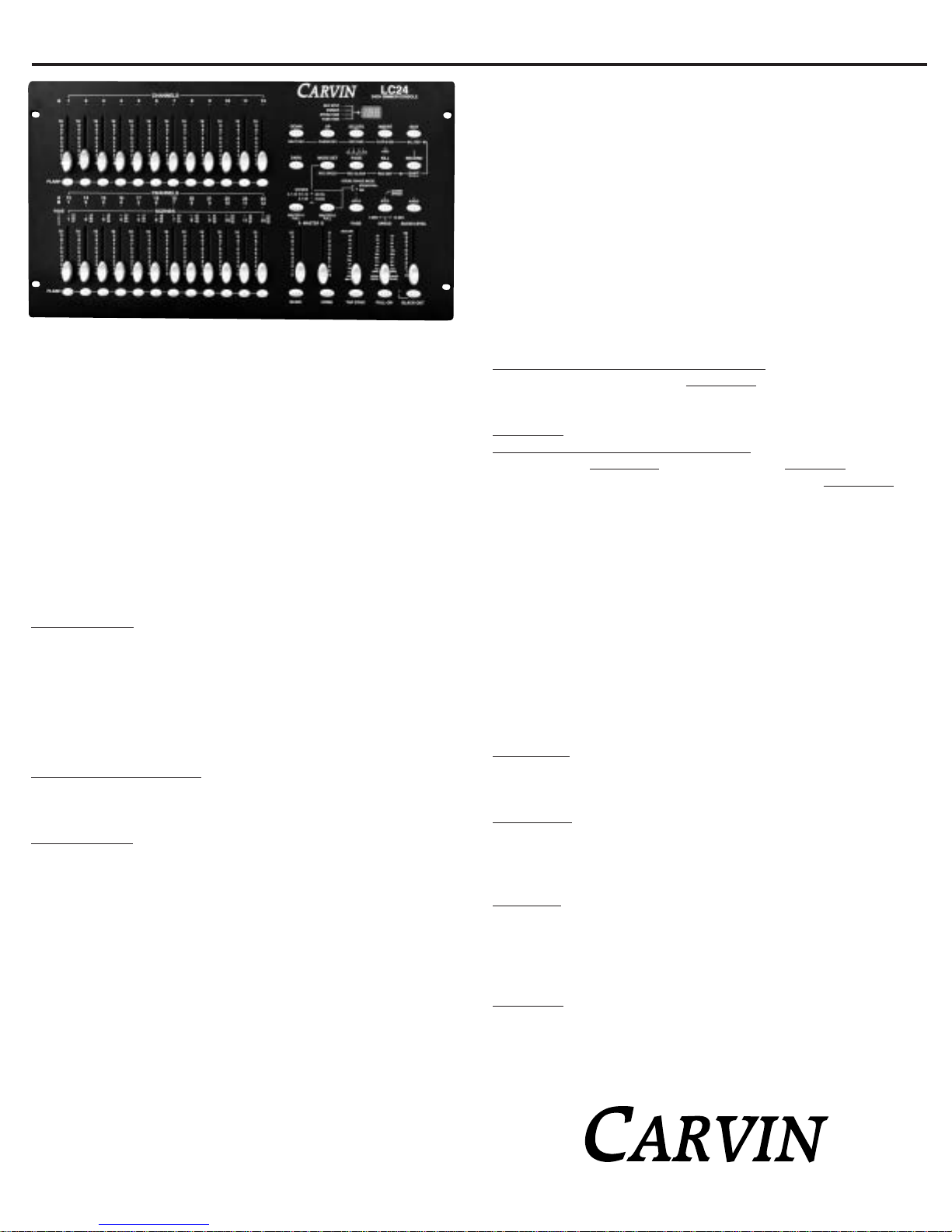
FRONT PANEL CONTROLS:
1.) CHANNEL A’S 1-12 LED’S
These LED’s show the channel FADER or FLASH button has
beenused. TheLED’s brightnessshows therelative levelthe
fader is set at. Also, this LED indicates when the channel is
turned on and when a program is running.
2.) CHANNEL A’S 1-12 FADERS
Theseare the faders used tocontroltheintensity of the light
on that channel. The intensity is in either 0-100% or from
0-255 steps.
3.) CHANNEL 1-12 FLASH BUTTONS
Whenpressedthechannelwilloutputthemaximumintensity.
4.)
CHANNEL B’S 1-12 OR A’S 13-24 LED’S
These LED’s show the CHANNEL FADER or FLASH button
hasbeenused. TheLED’sbrightnessshowstherelativelevel
the fader is set at. Also this LED indicates when the chan-
nel is turned on and when a program is running. The A and
B number are part of the mode setup.
5.) SCENES 1-12 LED’S
Wheninthescenesmode(alongwiththePagebutton) these
LED’s indicate which Scene or Scenes are running.
6.)
CHANNEL B’S 1-12 AND A’S 13-24 FADERS
Theseare the faders used tocontroltheintensity of the light
on that channel. The intensity is in either 0-100% or from
0-255steps. IntheSceneModethesefaderscontroltheinten-
sity of the scenes.
7.) CHANNEL B’S 1-12 AND A’S 13-24 FLASH
BUTTONS
When pressed the channel will output the maximum inten-
sity. Also these flash buttons are also used in storing pro-
grams in the recording mode.
8.) MASTER A FADER
This FADER will adjust the over all intensity of the channels
A1-12 in the 2x12 mode, A1-24 (all channels) in the 1x24
mode, and all user controlled channels (A1-12 and BLIND
BUTTON activated A13-24 channels) in the Scenes mode.
9.) BLIND BUTTON
IntheScenesmodethisbutton,whenactivated,returnscon-
trolof theSCENEFADERSandFLASH BUTTONS to theuser
andleavesthecurrentSceneprogramrunningwiththeinten-
sityleftinplace. Toworkthebutton pressandholdtheblind
buttonandthenpressthedesiredchannelsflashbutton. The
channelis returned toscenescontrolwith the Homebutton.
10.) MASTER B FADER
This Fader will adjust the over all intensity of the channels
B1-12inthe2x12mode,usedaspresetmasterwithMASTER
BFULL button in the 1x24 mode, and controls the over all
intensity of running scenes in the Scene mode.
11.) HOME BUTTON
In the Scenes mode this button, when activated, returns the
SCENEFADERSandFLASH BUTTONStocontrollingtheScene
programs. See Blind button.
12.) FADE FADER
Thisfaderadjuststhetimeacontrolledlighttakestogofrom
the off to maximum intensity and the same time is used for
going from maximum to off. This is called the fade time.
13.) TAP SYNC BUTTON
This button is used as an alternate way to define the chase
speed in Scenes mode. When tapping this button the time
betweenthelasttwotapsisthenewchasespeed. Thisbutton
over rides the Speed fader until the fader is used again.
14.)
SPEED FADER, 5MIN LED, & 10MIN LED
This fader adjusts the chase speed in the Scene mode.
SlowestspeedisdefineinthetwoLED’sabovethefader5min
or 10min. To change the lowest speed to 5 minutes press
and hold the RECORD button. While holding the RECORD
button down, press channel 5’s FLASH button three times.
After releasing the RECORD button, the 5MIN LED should
light. To change the lowest speed to 10 minutes press and
holdtheRECORDbutton. WhileholdingtheRECORDbutton
down,presschannel 10’S FLASH button three times. After
releasing the RECORD button, the 10MIN LED should light.
15.) FULL ON button
When pressed all channels with output at full intensity over
ride black out mode while pressed. The button works like a
flash button and only works while pressed.
16.) AUDIO FADER
This fader controls the sensitivity of the internal micro-
phone and audio input jack.
17.) BLACK OUT BUTTON & LED
The BLACK OUT button turns off all lights. One press of the
button turns on the BLACK OUT LED and the unit stays on
blackoutuntilthebuttonispressedagain. ThechannelFlash
buttons and the Full On flash button over ride the Black Out
button as long as they are held down.
18.) STEP BUTTON
IntheScenesmode,ifthechasespeedhasnotbeenset(the
chasespeedLEDisnotflashing)thenthisbuttoncanbeused
to step a program through one step pre button press. If the
chase LED is showing a chase speed, lower the speed fader
toits bottom "ShowMode"position now thestepbutton can
be used.
19.) AUDIO BUTTON & AUDIO LED
In Scene mode, the AUDIO button, when pressed, lights the
AUDIOLED andputs theconsoleintoAUDIOCHASE MODE.
If there is nothing inserted into the AUDIO IN RCA JACK the
audio input is the internal microphone. If the RCA JACK is
used the microphone is disabled. The audio chase mode is
exited by pressing the AUDIO button again.
20.) HOLD BUTTON & LED
WhentheHOLDbuttonispressedandheld,theconsolecur-
rent output for all channels is held. This allows all or any
fader change with out showing on the output until this
button is released. If a Scene is chasing the output at the
moment the HOLD button is pressed is held. The chase will
continueupon the release of the HOLD button. The channel
FLASH, The FULL ON, BLACK OUT, and DARK Buttons will
work during the hold button feature.
21.) MASTER A FULL, MASTER B FULL BUTTONS,
& SCENE CHASE MODE LED’S
In All three modes the MASTER A FULL button works like a
flash button for the MASTER A FADER. MASTER B FULL
button selects the Scene Chase Mode in the Scenes mode,
it works as a MASTER B FADER FLASH button in the 2x12
mode, and works as a single scene store button, with
MASTER B fader, in the 1x24 mode. The single scene store
feature stores a snap shot of the channel faders at the time
the MASTER B FULL button is pressed, this can be cleared
by lowering all the channel faders to 0 and pressing the
MASTER B FULL button. In Scenes mode, the Sequential
scene chase mode runs multiple scene programs sequen-
tially, and the Mix mode runs multiple scene programs
simultaneously.
22.) KILL / REC EXIT BUTTON & YELLOW ADD LED
PressingtheKILLbuttonturnsontheADD LEDandputsthe
console in kill mode. Kill mode works when any or multiple
channel Flash buttons are press. The pressed flash buttons
lighttheirchannelsandturnoffallotherchannelsforaslong
asonechannelflashbuttonisstillhelddown.Inrecordmode
by pressing the RECORD/SHIFT button holding it and then
theKILL / REC EXIT button upon the releaseofbothbuttons
Record mode will be exited. See the Record Mode section.
23.) RECORD / SHIFT BUTTON & RED LED
The RECORD button is used to enter the record mode by
pressing and holding the record button, then sequentially
pressingFLASH 1,FLASH 5,FLASH 6,andFLASH8. When
theRECORD buttonisreleasedtheredRECORD LEDwilllight
and the console is in record mode. In record mode the
RECORD button is used to record each step of a program.
The SHIFT function activates the alternate functions on the
undersideofthe%or0-255 buttonandtheREC CLEARand
REC EXIT buttons, that only work in Record mode. To acti-
vate an alternate button function press and hold the
RECORD/SHIFT button and then press the desired alternate
button. When both buttons are released the alternate func-
tion will be implemented.
24.) PAGE BUTTON / REC CLEAR BUTTON &
GREEN 1-4 LED’S
In Scene mode the PAGE button selects which scene pro-
grams the channel B 1-2 fader control. The 4 pages times
the 12 channel B faders equals the 48 possible scene pro-
grams. In the Record mode the PAGE button along with a
channel B FLASH button select where a program is stored.
Alsoin Recordmode thealternate(see Record/Shiftbutton)
REC CLEAR function clears the current program.
25.)
MODE SET / REC SPEED BUTTON & 3 MODE LED’S
The Mode Set button toggles through the three operating
modes and LED’s. In Scene mode the alternate Rec Speed
functionassignsachasespeedtoanysceneprogram. First,
selectthedesiredchasespeed,viathespeedfaderorthetap
syncbutton,thenpressandholdtheREC SPEEDbuttonand
the desired Scene’s FLASH button. When both buttons are
LC24 24CH LIGHTING CONSOLE

released the scene program is locked so that chase speed
andotherprogramscanbesettonewchasespeeds. Toreturn
a Scene program’s chase speed control to the speed fader,
placethe Speed fader in the bottom SHOW MODE position.
Pressandholdthe REC SPEEDbutton alongwith theScene
programs FLASH button upon release of both buttons the
control is restored.
26.) DARK BUTTON
The DARK button is like a momentary version of the
BLACKOUTbutton. ExcepttheDARK buttoncannotbeover
ridden by any other button while still pressed.
27.) ALL REV BUTTON / EDIT
TheALL REV buttonworksin the Scenesmode. Itreverses
the direction of the chase for all scene programs running
whether or not a chase speed was set using the Rec Speed
button.InrecordModeandinScenemodethealternateEdit
function pressed in conjunction with a scene flash button
puts the console in the edit mode of that scene program.
See Record Mode.
28.) % OR 0-255 / INSERT BUTTON
The% OR 0-255 button is used tochangethedimmer read-
out on the LED display from 0-100% to 0-255 steps. This
is only a display reading preference. The function toggles
every time the RECORD and "% OR 0-255" buttons are
pressandthesametime.ThealternateInsertfunction works
in the record Edit mode. It is used to insert a new step into
an existing program.
29.) REV ONE / DELETE BUTTON
The REV ONE button reverses the scene program who’s
FLASH button is pressed at the same time. The alternate
Delete function works in the record Edit mode. It is used to
deletea new step into an existing program.
30.) CHASE REV / UP BUTTON
The CHASE REV button works in the Scene mode and
reverses the chase direction of the any programs running
to a chase speed it will not rev scene programs that have
their chase speed set by using the REC SPEED button. The
UP function works in the record Edit mode. It is used to
changethe dimmer intensity in an existingprogram. In the
recordEditmode,astepsdimmerintensityvalueischanged
by pressing and holding the UP button, then as the FLASH
buttonunderthechanneltobemodifiedispressedtheinten-
sity is increased. The alternate Chase Rev function works
in the Scene mode and reverses the chase direction of the
anyprograms running to a chasespeeditwill not rev scene
programs that have their chase speed set by using the REC
SPEED button.
31.) BEAT REV / DOWN BUTTON
The BEAT REV button works in the Scene mode with scene
programsthathavetheirchasespeedsetbytheREC SPEED
buttonandarenowrunningwithotherprogramswithaudio
chaseactivated.TheSetSpeedchaseprogramswillreverse
onthenextbeat(mayhavetoholdthebuttonfortwobeats)
after the button is released.
Thealternate Downfunction worksinthe recordEdit mode.
It is used to change the dimmer intensity value of a step in
anexistingprogram. IntherecordEditmode,astep’s dimmer
intensityvalue is change by pressing andholdingtheDown
button,thenastheFlashbuttonunderthechanneltobemod-
ified is pressed the intensity is decreased.
REAR PANEL CONTROLS:
32.) POWER INPUT JACK
Use supplied AC wall adapter.
33.) MIDI THRU
UseforserialconnectionsofmoreMIDIdevicesconnected
after the LC24. Has same MIDI information as going into
the MIDI in jack.
34.) MIDI OUT
Use for send out MIDI information from the LC24.
35.) MIDI IN
Used for receiving MIDI information into the LC24.
36.) DMX OUTPUT
UsedforsendinformationtoDimmerpacksetc..intheDMX-
512 format.
37.) DMX POLARITY SELECT
Reverses the polarity of the balanced DMX lines. Used if
Dimmer packs etc.. used with the LC24 only conform to a
certainpolarity. SeeDimmerpackandotherperipheralsfor
correct polarity. The polarity will not damage peripherals,
buttheymaynotfunctionproperlywithanincorrectsetting.
38.) THE AUDIO INPUT
Theaudioinputjackwhenusedturnsofftheinternalmicro-
phone. Ican handlefrom100mV to1Vpp andiscontrolled
bytheaudiofader.Thisjackisusedtocontrolthechaserate
of a scene program with an audio source.
39.) REMOTE CONTROL INPUT:
The stereo (TRS) 1/4" jack is used to remotely control the
FullOnandBlackOutfeaturesoftheconsole. Thetipisthe
Full On control. It works in either momentary hold or push
on push off. The Ring is the
BlackOutcontrolandworksas
pushon/pushoff. Thisisthe
samearetheseswitcheswork
on the front console.
1
2
3
4
5
6
7
8910 11 12 13 14 15 16 17
18
20
19
21 22
23 24
25 26
27 28
29
30
31
LC24 REAR CONNECTIONS
32 33 34 35 36 37 38 39


Table of contents
Popular Dj Equipment manuals by other brands

Ibiza
Ibiza MAGIC-COLOR-STICK-1.0BK manual

Coemar
Coemar LEDko FullSpectrum 6 HD user manual

Chauvet DJ
Chauvet DJ SlimPAR Q12 BT Quick reference guide

EuroLite
EuroLite LED TMH-X25 Zoom user manual

Squareled
Squareled Ventura 6x25W RGBAW Matrix Bar user manual

EuroLite
EuroLite DMX Scan Control 192 MK2 user manual