Cascade Sciences CDO-5-2 User manual

Installation - Operation Manual
CDO-5-2
Drying — Decarboxylation Oven
220 – 240 Voltage

2 | Page
cascadesciences.com |Tel. 503 847-9047
The CDO-5-2 requires a 220 – 240-volt power supply outlet to plug into.
Warning:This product contains chemicals, including Triglycidyl Isocyanurate, known to the State of
California to cause cancer as well as birth defects or other reproductive harm. For more information
go to www.P65Warnings.ca.gov.
¡Advertencia! Este producto contiene sustancias químicas, incluido el triglicidil isocianurato, que el
estado de California sabe que causa cáncer, así como defectos de nacimiento u otros daños
reproductivos. Para obtener más información, visite www.P65Warnings.ca.gov.
Avertissement!Ce produit peut vous exposer à des produits chimiques, dont l'isocyanurate de
triglycidyle, reconnu par l'État de Californie pour provoquer le cancer, des anomalies congénitales
ou d'autres problèmes de reproduction. Pour plus d'informations, visitez le site
www.P65Warnings.ca.gov

3| Page
cascadesciences.com |Tel. 503 847-9047
CDO Drying and Decarboxylation Oven
220 – 240 Voltage
Installation and Operation Manual
Part Number (Manual): 4861782
Revision: November 7, 2019

4 | Page
cascadesciences.com |Tel. 503 847-9047
TABLE OF CONTENTS
CERTIFICATIONS ...................................................................................................................................................... 5
UNIT SPECIFICATIONS .............................................................................................................................................7
Temperature Performance .................................................................................................................................................. 7
HVAC Load .............................................................................................................................................................................. 7
Power......................................................................................................................................................................................... 7
Airflow Performance ..............................................................................................................................................................8
Weight........................................................................................................................................................................................8
Dimensions...............................................................................................................................................................................8
Capacity ....................................................................................................................................................................................8
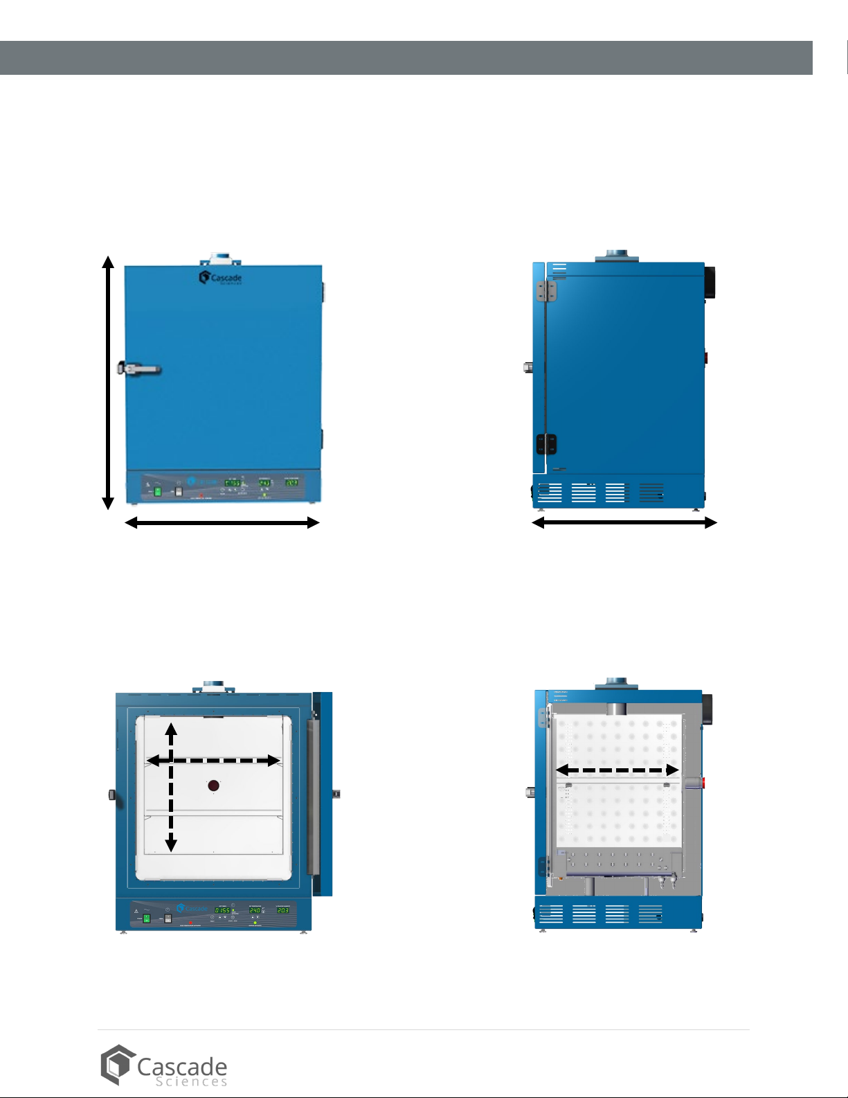
Unit Dimension Drawings.....................................................................................................................................................9
INTRODUCTION ........................................................................................................................................................11
Read this Manual................................................................................................................................................................... 11
Contacting Assistance ......................................................................................................................................................... 11
Engineering Improvements................................................................................................................................................. 11
RECEIVING YOUR UNIT ..........................................................................................................................................13
Inspect the Shipment........................................................................................................................................................... 13
Orientation Images .............................................................................................................................................................. 14
Recording Data Plate Information................................................................................................................................... 16
INSTALLATION .........................................................................................................................................................17
Installation Procedure Checklist .......................................................................................................................................17
Required Ambient Conditions........................................................................................................................................... 18
Required Clearances........................................................................................................................................................... 18
Power Source Requirements ............................................................................................................................................ 19
General Power Safety ........................................................................................................................................................ 20
Lifting and Handling ........................................................................................................................................................... 20
Leveling................................................................................................................................................................................... 21
Install the Oven ..................................................................................................................................................................... 21
Installation Cleaning............................................................................................................................................................ 21
Install the Shelving.............................................................................................................................................................. 22
Access Port Stopper ........................................................................................................................................................... 22
GRAPHIC SYMBOLS ............................................................................................................................................... 23
CONTROL OVERVIEW ............................................................................................................................................25
OPERATION.............................................................................................................................................................. 27
Safety Guidelines .................................................................................................................................................................27
Operating Precautions....................................................................................................................................................... 28
Theory of Operation ........................................................................................................................................................... 29
Put the Oven into Operation ............................................................................................................................................. 31
Set the Temperature Setpoint ......................................................................................................................................... 32
Setting the Timer ................................................................................................................................................................. 33
Launch a Heating Profile................................................................................................................................................... 35
Drying Racks and other Accessories............................................................................................................................. 36
USER MAINTENANCE............................................................................................................................................. 37
Cleaning and Disinfecting..................................................................................................................................................37
Door Gaskets and Chamber Integrity ........................................................................................................................... 38
Electrical Components....................................................................................................................................................... 38
Calibrating the Temperature Display ............................................................................................................................ 39
PARTS LIST............................................................................................................................................................... 43

5| Page
cascadesciences.com |Tel. 503 847-9047
CERTIFICATIONS
This certificate satisfies NRTL safety requirements
TÜV SÜD CUE
These units are CUE listed by TÜV SÜD as forced air ovens for appropriate professional, industrial,
or educational use. TÜV SÜD America Inc. is an OSHA recognized NRTL and a Standards Council of
Canada accredited certification body.
The units have been tested to the following requirements:
CAN/CSA-22.2 No. 61010-1:2012/U2:2016-04
CAN/CSA-C22.2 No. 61010-2-010:2015
UL 61010-1:2012/R:2016-04
UL 61010-2-010:2015
EN 61010-1:2010
EN 61010-2-010:2014

6 | Page
cascadesciences.com |Tel. 503 847-9047
CERTIFICATIONS

7| Page
cascadesciences.com |Tel. 503 847-9047
UNIT SPECIFICATIONS
These ovens are 220 – 240 voltage single-phase units. Please refer to the oven data plate for individual
electrical specifications.
Technical data specified applies to units with standard equipment at an ambient temperature of 25°C and
at nominal voltage. The temperatures specified are determined in accordance with factory standards
respecting the recommended wall clearances of 10% of the height, width, and depth of the inner chamber.
All indications are average values, typical for units produced in the series. We reserve the right to alter
technical specifications at all times.
TEMPERATURE PERFORMANCE
Range Stability @ All Temps.
Ambient +36°to 300°F* ± 0.4°F
*As set at the factory, the oven controller software restricts the maximum operating temperature to
300°F. Contact Cascade Sciences to unlock the temperature restriction if you want to use the oven
for applications other than biomass decarboxylation running above the factory-restricted max
temperature.
The maximum unrestricted chamber temperature the oven can achieve is 350°F (177°C). Do not use
mesh bags at temperatures exceeding 240°F (115°C)!
Uniformity @100°F Uniformity @240°F Uniformity @305°F
1.0°F ±1.5°F ±3.0°F
Heat Up Times from Ambient (77°F)
To 240°F
40 Minutes
HVAC LOAD
BTU/Hour
3216
POWER
AC Voltage Amperage Frequency Phase Energy Consumption
220 – 240
10.0
50/60 Hz
1
22.6 kWh/Day

8 | Page
cascadesciences.com |Tel. 503 847-9047
SPECIFICATIONS
AIRFLOW PERFORMANCE
Air Exchanges
@176°F
220 per Hour
Linear Shelf Space Airflow
Linear Feet per Minute Linear Meters per Minute
145 44
Exhaust Air Flow @ 176°F
Cubic Feet Liters
18.5 per Minute 523.9 per Minute
WEIGHT
Shipping Unit Weight
258 lb / 117 kg 208.0 lb / 94.3 kg
DIMENSIONS
By Inches
Exterior W × D × H Interior W × D × H
31.4 x 28.1 x 38.8 21.0 x 19.4 x 20.7
By Millimeters
Exterior W × D × H Interior W × D × H
798 x 714 x 986 533 x 494 x 527
CAPACITY
Volume
Cubic Feet Liters
4.90 138.0
Shelf Capacity by Weight
Per Shelf Total
50 lb / 22.7 kg* 200 lb / 91.0 kg**
*50 lb / 22.7 kg with weight evenly distributed across the shelf.
**200 lb / 91.0 kg total load. Exceeding this limit risks damaging the chamber liner.

9| Page
cascadesciences.com |Tel. 503 847-9047
SPECIFICATIONS
UNIT DIMENSION DRAWINGS
Total Height: 38.8 inches (986 mm)
Width: 31.4 inches (798 mm)
Depth: 28.1 inches (714 mm)
Chamber Interior
Depth: 19.4 inches (494 mm)
Width: 21.0 inches (533 mm)
Height: 20.7 inches (527 mm)
Cutaway Side View
Exterior Dimensions

10 | Page
cascadesciences.com |Tel. 503 847-9047
SPECIFICATIONS

11 | Page
cascadesciences.com |Tel. 503 847-9047
INTRODUCTION
READ THIS MANUAL
Failure to follow the guidelines and instructions in this user manual may create a protection
impairment by disabling or interfering with the unit safety features. This can result in injury or death.
Before using the unit, read the manual in its entirety to understand how to install, operate, and
maintain the unit in a safe manner. Ensure all operators are given appropriate training before the unit
begins service.
Keep this manual available for use by all operators.
Intended Applications and Locations
CDO forced-air ovens are engineered for constant temperature forced-air drying, curing, and baking
applications in professional, industrial, and educational environments. The ovens are not intended
for use at hazardous or household locations.
CONTACTING ASSISTANCE
Please have the following information ready when calling or emailing Technical Support: the model
number and the serial number (see page 16).
Phone: 503 847-9047
Cascade Sciences
6725 NE Evergreen Pkwy
Ste 106
Hillsboro OR, 97124
ENGINEERING IMPROVEMENTS
Cascade Sciences continually improves all of its products. As a result, engineering changes and
improvements are made from time to time. Therefore, some changes, modifications, and improvements
may not be covered in this manual. If your unit’s operating characteristics or appearance differs from
those described in this manual, please contact your oven dealer or customer service representative for
assistance.

12 | Page
cascadesciences.com |Tel. 503 847-9047
INTRODUCTION

13 | Page
cascadesciences.com |Tel. 503 847-9047
RECEIVING YOUR UNIT
INSPECT THE SHIPMENT
•When a unit leaves the factory, safe delivery becomes the responsibility of the carrier.
•Damage sustained during transit is not covered by the manufacturing defect warranty.
•Save the shipping carton until you are certain that the unit and its accessories function
properly.
When you receive your unit, inspect it for concealed loss or damage to its interior and exterior. If you
find any damage to the unit, follow the carrier’s procedure for claiming damage or loss.
1. Carefully inspect the shipping carton for damage.
2. Report any damage to the carrier service that delivered the unit.
3. If the carton is not damaged, open the carton and remove the contents.
4. Inspect the unit for signs of damage. See the orientation depiction on the next page as a
reference.
5. The unit should come with an Installation and Operation Manual.
6. Verify that the correct number of accessory items have been included.
7. Carefully check all packaging for loose accessory items before discarding.
Included Accessory Items:
A high-temperature access port stopper ships installed in the port located on the back of the
oven.
Shelves Shelf Clips Leveling Feet Power Cord NEMA Power Cord EUR
2
8
4
1
1

14 | Page
cascadesciences.com |Tel. 503 847-9047
CDO
-5-2
RECEIVING
ORIENTATION IMAGES
Exhaust Port with Sliding Dampener
Main Temperature and OTL Sensor Probes
Door Latch
Control Panel
Chamber Liner Gasket
Access Port
Oven Chamber

15 | Page
cascadesciences.com |Tel. 503 847-9047
RECEIVING
Unit Back
Fan
Access Port (Stopper Installed)
Power Cord Inlet
(Holds 1st Fuse)
Fuse Holder
(Holds 2nd Fuse)
Data Plate

16 | Page
cascadesciences.com |Tel. 503 847-9047
RECEIVING
RECORDING DATA PLATE INFORMATION
Record the unit model number and serial number below for future reference.Your distributor or
Tech Support needs this information to provide accurate help during support calls and emails.
•The data plate is located on the back of the oven, just above the power cord inlet.
Date Plate Information
MODEL NO:
SERIAL NO:

17 | Page
cascadesciences.com |Tel. 503 847-9047
INSTALLATION
INSTALLATION PROCEDURE CHECKLIST
For installing the oven in a new workspace location.
Pre-Installation
Check that the required ambient conditions for the oven are met, page 18.
Verify the spacing and clearance requirements are met, page 18.
•Unit dimensions may be found on page 7.
Check that a suitable electrical outlet and power supply is present, page 19.
Install the oven in a suitable workspace location
Review the lifting and handling instructions, page 20.
Install the leveling feet, page 21.
Install the oven in its workspace location, page 21.
Set up the oven for use
Clean the oven shelving. Clean the chamber if needed, page 21.
Install the shelving, page 22.
Verify the stopper is installed in the access port on the outside of the oven, page 22.

18 | Page
cascadesciences.com |Tel. 503 847-9047
INSTALLATION
REQUIRED AMBIENT CONDITIONS
These units are built for use indoors at room temperatures between 15°C and 40°C (59°F and 104°F) at
no greater than 80% Relative Humidity (at 25°C / 77°F). Operating outside these conditions may
adversely affect the unit temperature performance.
When selecting a location to install the unit, consider all environmental conditions that can adversely
impact its temperature performance. These include:
•Proximity to other ovens, autoclaves, or any other device producing significant radiant heat
•Heating and cooling vents or other sources of fast-moving air currents
•High-traffic areas
•Direct sunlight
REQUIRED CLEARANCES
These clearances are required to provide air flows for ventilation and cooling.
6 inches (152 mm) of clearance is required on the sides.
24 inches (610 mm) of headspace clearance is required between the exhaust vent and any
overhead cover or partition.
o12 inches (305 mm) of vertical headspace clearance will suffice if the oven exhaust is
vented from the workspace through a duct or other channeling.
Do not place objects on top of the oven.
Allow at least 6 inches (152 mm) from the access port and fan vent on the back of the oven to the
nearest wall or partition. Keep the fan unobstructed at all times.
6” (152 mm) Fan
6” (152 mm)
6” (152 mm)
12” (305 mm)
24” (610 mm)
24” (610 mm)
Door Swing 32”
(813mm)
Access Port
12” (305 mm) if
ducting is attached

19 | Page
cascadesciences.com |Tel. 503 847-9047
INSTALLATION
POWER SOURCE REQUIREMENTS
When selecting a location for the oven, verify each of the following requirements is satisfied.
Power Source: The power supply must meet the power requirements listed on the oven data plate
(located on the back of the unit, beneath the power feed inlet.
•These ovens are intended for a 220 – 240 volt, 50/60 Hz applications at 10 amps.
•The power source must be single (1) phase and protective earth grounded.
•The power source must conform to all national and local electrical codes.
•Supplied voltage must not vary more than 10% from the data plate rating. Damage to the
oven may result if the supplied voltage varies more than 10%.
•The recommended wall circuit breakers for these units are 20 amps.
•Use a separate circuit to prevent loss of the unit due to overloading or circuit failure. The
circuit must meet or exceed the amperage requirements listed on the oven data plate.
Power Cord. The unit must be positioned so that all operators can quickly unplug the oven in the
event of an emergency.
•The unit comes provided with a 250V, 10 Amp, 2.5m (8ft) Euro CEE7/7 power cord.
•This unit is also provided with a 250V, 15A, 8ft 2in (2.5m) NEMA 6-15P power cord.
Fuses: The unit ships with two 10 Amp fuses. One in the power cord inlet and the other in an
adjacent fuse holder.
•The fuses must be installed and intact for the unit to function.
•Always determine the cause of a blown fuse before restoring the unit to operation.
EURO CEE7/7
Outlet
NEMA 6-15R
Outlet

20 | Page
cascadesciences.com |Tel. 503 847-9047
INSTALLATION
GENERAL POWER SAFETY
Your unit and its recommended accessories are designed and tested to meet strict safety
requirements. It is designed to connect to a power source using the specific power cord type
shipped with the unit.
For continued safe operation of your unit, always follow basic safety precautions including:
•Always plug the unit power cord into a protective earth grounded electrical outlet that
conforms to national and local electrical codes. If the unit is not grounded properly, parts
such as knobs and controls can conduct electricity and cause serious injury.
•Do not bend the power cord excessively, step on it, or place heavy objects on it.
•A damaged cord can be a shock or fire hazard. Never use a power cord if it is damaged or
altered in any way.
LIFTING AND HANDLING
The oven is heavy. Use appropriate lifting devices that are sufficiently rated for these loads. Follow these
guidelines when lifting the oven:
•Lift the oven only from its bottom surface.
•Doors, handles, and knobs are not adequate for lifting or stabilization.
•Restrain the oven completely while lifting or transporting so it cannot tip.
•Remove all moving parts, such as shelves and trays, and lock doors in the closed position
during transfers to prevent shifting and damage.
Table of contents
Other Cascade Sciences Oven manuals