Caswell CAD-0205 User manual

CAD-0205 Series
Communication Appliance
Users Manual
Revision: 1.4
CE
This certificate of conformity of CAD-0205 series with actual required safety standards in
accordance with 89/366 ECC-EMC Directive and LVD 73/23 ECC
UL
This product meets all safety requirements per UL60950 standard.

CAD-0205 Series User’s Manual
1
Table of Contents
Chapter 1 Introduction.............................................................................2
1.1 About This Manual...................................................................................2
1.2 Manual Organization................................................................................2
1.3 Technical Support Information.................................................................2
1.4 Board Layout ....………………………………………………………………..3
1.5 System Block Diagram.............................................................................3
1.6 Product Specification...............................................................................4
Chapter 2 Getting Started...........................................................................5
2.1 Included Hardware...................................................................................5
2.2 Before You Begin.....................................................................................5
2.3 Hardware Configuration Setting...............................................................6
2.4 The Chassis .......................................................................................9
2.5 Open the Chassis....................................................................................9
2.6 Hard drive Install....................................................................................11
2.7 Thermal Pad Install................................................................................11
2.8 Remove and Install DIMM......................................................................12
2.9 Remove and Install CF card...................................................................14
2.10 Use a Client Computer ..........................................................................15
Chapter 3 BIOS Setting.........................................................................17

CAD-0205 Series User’s Manual
2
Chapter1 Introduction
1.1 AboutThisManual
This manual contains all required information for setting up and using the CAD-0205 series.
CAD-0205 provides the essential platform for delivering optimal performance and functionality in
the entry communications appliance market segment. This manual should familiarize you with
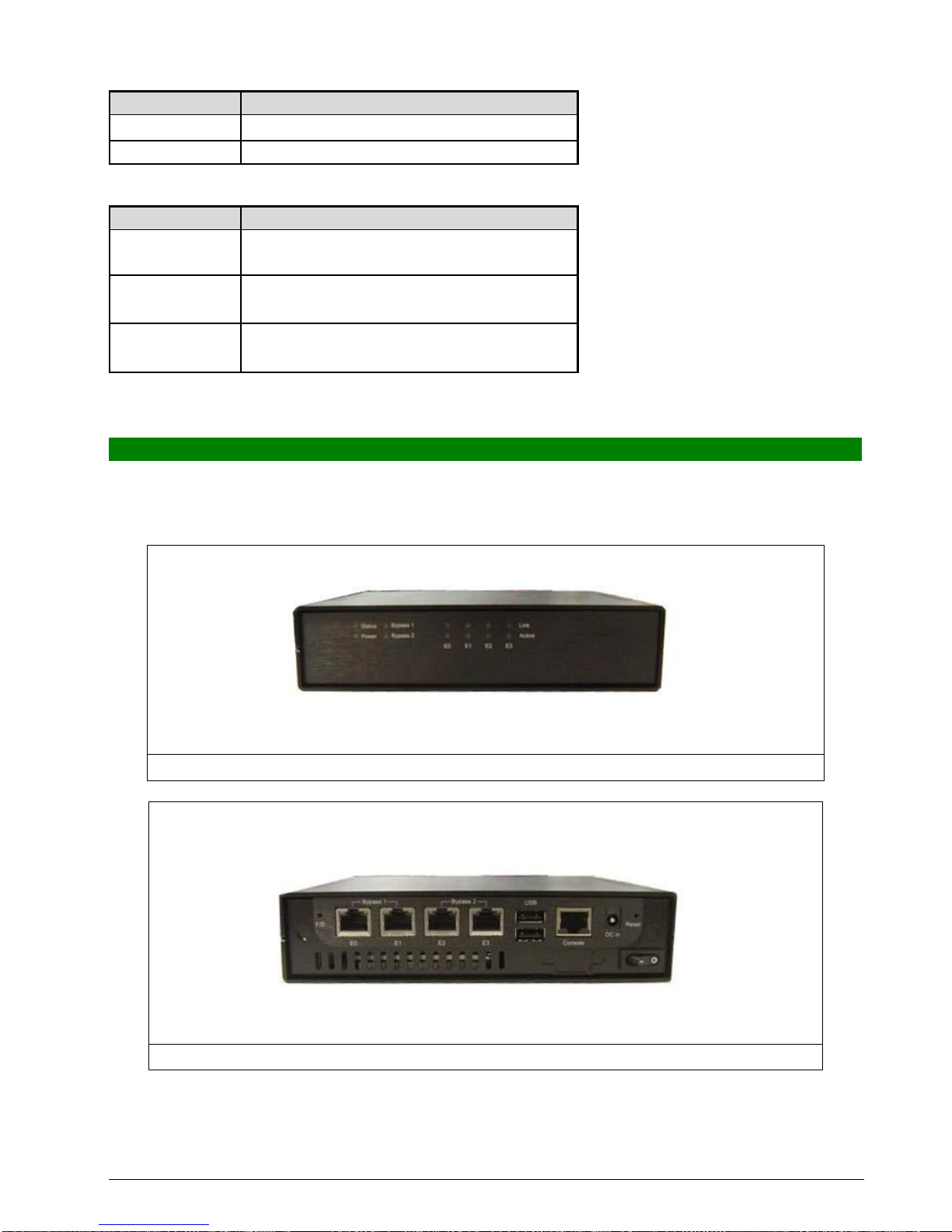
CAD-0205 operations and functions.CAD-0205-3421 series provide up to 4 on-board Ethernet
ports to serve communication applications like Firewall, requiring 4 Ethernet ports to connect
external network (internet), demilitarized zone and internal network.
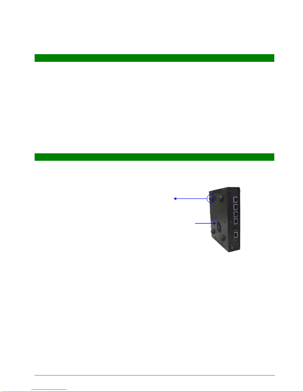
CAD-0205 series overview:
INTELAtom N450 1.66GHz
Memory: One DDR2 SODIMM slot and up to 2G
Four Gigabit Ethernet interfaces with two Bypass segments
Independent management console(RS232)
One min-PCI -E socket for mini-PCI-E / USB device connectivity.
One 2.5” SATA Hard disk
1.2 Manual Organization
This manual describes how to configure your CAD-0205 system to meet various operating
requirements. It is divided into three chapters, with each chapter addressing the basic concept
and operation of this system.
Chapter 1: Introduction. This section describes how this document is organized. It includes brief
guidelines and overview to help find necessary information.
Chapter 2: Hardware Configuration Setting and Installation. This chapter demonstrated the
hardware assembly procedure, including detailed information. It shows the definitions
and locations of Jumpers and Connectors that can be used to configure the system.
Chapter 3: Operation Information. This section provides illustrations and information on the system
architecture and how to optimize its performance.
Any updates to this manual, would be posted on the web site:
http://www.cas-well.com/products/index.php
1.3 TechnicalSupportInformation
Users may find helpful tips or related information on Caswell's web site: http://www.cas-well.com A
direct contact to Caswell's technical person is also available. For further support, users may also
contact Caswell’s headquarter in Taipei or local distributors.
Taipei Office Phone Number: +886-2-7705-8888

CAD-0205 Series User’s Manual
3
1.4 BoardLayout
Figure 1-1 Board Layout of CAD-0205 M/B
1.5 System Block Diagram
Figure 1-2 CAD-0205 Basic Block Diagram
Pineview-M
ICH8M
PCI-E
GbE-0
82583V
PCI-E
GbE-1
82583V
PCI-E
GbE-2
82583V
PCI-E
GbE-3
82583V
RJ45
RJ45
RJ45
RJ45
SODIMM
DDR2 667
Onboard VGA
Pin header
Bypass 0
BIOS/Firmware
Dual
USB
Ports
RJ45
System
Console
2xSATA
slot
CF Socket
Mini PCIe
slot
PCI-E x1
Bypass 1

CAD-0205 Series User’s Manual
4
1.6 Product Specification
Feature
Detailed Description
1
CPU
․Onboard ATOM N450 1.66GHz processor
2
CPU Board
․CAPB-0205VD with Intel ATOM N450+ ICH8M
․Board dimension: 170x140mm
3
System
Memory
․1 x 200-pin SO-DIMM socket
․Support DDR2 667 max. up to 2GB, non-ECC
4
VGA Interface
․1 x Internal VGA pin header (2 x 5-pin)
․A semi-cutting hole for standard D-Sub 15-pin VGA connector on
chassis.
PCI-E Ethernet
․Max. four PCI-E GbE ports base on Intel 82583V
5
Storage Device
․1 x SATA 2.5” Hard disk
․1 x CF
6
Expansion slots
․1 x mini PCI-E
7
Chassis
․Form factor: 1U desktop chassis
․To accommodate: M/B, HDD bracket for 2.5”
․Dimension: 182x140x40mm
8
Front Panel
Ethernet interfaces: Four RJ45 Ethernet connectors.
RS232 interface: RS232 port with RJ45 connector for system console
USB interface: dual-USB connectors
Hardware Reset Button
LED:
-
-
System LED: Power and Data access.
-
-
Ethernet LED
9
Rear Panel
AC power inlet
A semi-cutting hole for 15-pin VGA connector
A semi-cutting hole for wireless antenna
10
PSU
40W, 12V power adapter
11
Dimension
182x150x40mm
12
Environmental
requirements
Storage temp.: -20°C to 75°C
Operating temp.: 0°C to 35°C.Fanless
Humidity: 10 to 90% RH non-condensing

CAD-0205 Series User’s Manual
5
Chapter2 GettingStarted
This section describes how the hardware installation and system settings should be done.
2.1 Included Hardware
The following hardware is included in package:
CAD-0205 Communication Appliance System Board
One null serial port cable
AC-DC Adapter
Hard disk ground cable
Chassis foot pad
SATA cable
2.2 BeforeYou Begin
If you are not running on fan-less type then you should install foot pad to chassis before testing.
There are four foot pads should be installed.
Foot pad
FAN air flow
To prevent damage to any system board, it is important to handle it with care. The following
measures are generally sufficient to protect your equipment from static electricity discharge:
When handling the board, use a grounded wrist strap designed for static discharge elimination
and touches a grounded metal object before removing the board from the antistatic bag. Handle
the board by its edges only; do not touch its components, peripheral chips, memory modules or
gold contacts.
When handling processor chips or memory modules, avoid touching their pins or gold edge
fingers. Restore the communications appliance system board and peripherals back into the
antistatic bag when they are not in use or not installed in the chassis.
Some circuitry on the system board can continue operating even though the power is switched off.
Under no circumstances should the Lithium battery cell used to power the real-time clock be
allowed to be shorted. The battery cell may heat up under these conditions and present a burn
hazard.

CAD-0205 Series User’s Manual
6
WARNING!
1. "CAUTION: DANGER OF EXPLOSION IF BATTERY IS INCORRECTLY REPLACED. REPLACE
ONLY WITH SAME OR EQUIVALENT TYPE RECOMMENDED BY THE MANUFACTURER.
DISCARD USED BATTERIES ACCORDING TO THE MANUFACTURER’S INSTRUCTIONS"
2. This guide is for technically qualified personnel who have experience installing and
configuring system boards. Disconnect the system board power supply from its power source
before you connect/disconnect cables or install/remove any system board components.
Failure to do this can result in personnel injury or equipment damage.
3. Avoid short-circuiting the lithium battery; this can cause it to superheat and cause burns if
touched.
4. Do not operate the processor without a thermal solution. Damage to the processor can occur
in seconds.
5. Do not block air vents. Minimum 1/2-inch clearance required.
2.3 Hardware Configuration Setting
2.3.1 CAD-0205 System
2.3.2 CAD-0205 System Board Jumper
In general, jumpers on CAD-0205 system board are used to select options for certain
features. Some of the jumpers are configurable for system enhancement. The others
are for testing purpose only and should not be altered. To select any option, cover the
jumper cap over (Short) or remove (NC) it from the jumper pins according to the following
instructions. Here NC stands for “Not Connected”.

CAD-0205 Series User’s Manual
7
Location of Jumpers
CAPB-0205 R2 Jumper Setting: (Default Setting:””)
Connector
Function
Remark
J1
8-bit GPIO connector
J2
VGA connector
J3
Debug Header
J5
KB + MS Header
J6
Mini PCI Express Card Socket
J7
CF socket
J8
DDR2 DIMM Slot
J9
+5V & +12V Power Connector (Only Output)
J10,J11
SATA connector
J12
USB connector
J13~J16
RJ45 connector
J17
Console Port
J18
DC Power Jack
JP1
CMOS Clear Header
JP4,JP5
By-pass and normal mode
JP7
SMB Header
JP13
MCU Programming Header
D2
HDD LED +Power LED
D3
By-pass LED
JP17
JP15

CAD-0205 Series User’s Manual
8
D4~D7
LAN LED
U32
SYS Reset Switch
U33
Default Factory Switch
J1:8-bit GPIO Header Definition
Pin
Signal Name
Pin
Signal Name
1
GPIO
2
GPIO
3
GPIO
4
GPIO
5
GPIO
6
GPIO
7
GPIO
8
GPIO
9
Ground
10
+5V
J2:VGA Header Definition
Pin
Signal Name
Pin
Signal Name
1
RED
2
DDCCLK
3
GREEN
4
Ground
5
BLUE
6
DDCDATA
7
HSYNC
8
Ground
9
VSYNC
10
N/C
J3 : Debug Header Definition
Pin
Signal Name
Pin
Signal Name
1
LAD0
2
+3.3V
3
LAD1
4
RESET#
5
LAD2
6
LFRAME#
7
LAD3
8
CLOCK
9
NC
10
GND
J5:KB+MS Header Definition
Pin
Signal Name
Pin
Signal Name
1
Mouse DAT
2
Keyboard DAT
3
NC
4
NC
5
GND
6
GND
7
+5V
8
+5V
9
Mouse CLOCK
10
Keyboard CLOCK
J9:+5V & +12V Power Connector (Only Output)
Pin
Signal Name
1
VDD_12V
2
GND
3
GND
4
VDD_5V
JP1:CMOS Clear
JP1
Function
1-2 Short
Normal Operation *
2-3 Short
Clear CMOS Contents

CAD-0205 Series User’s Manual
9
JP4, JP5:By-pass Function Header
JP4, JP5
Function
1-2 Short
Bypass Function *
2-3 Short
Bypass Function Disable
JP15, JP17 : BIOS Bypass Mode Options Header
JP15, JP17
Function
1-2、3-4、5-6、
7-8 short
Default *
1-2、3-4、5-6、
7-8、9-10 Short
Bypass Function: Non_normal Bypass mode
1-2、3-4、5-6、
7-8、9-10 Open
Bypass Function: Non_normal Open mode
2.4 The Chassis
The system is integrated in a 1U desktop chassis (Fig. 2-1, Fig. 2-2). On the front panel you will
find a Power / HDD / Ethernet LED.
Fig. 2-1 Front view of the chassis
Fig. 2-2 Rear view of the chassis

CAD-0205 Series User’s Manual
10
2.5 Open the Chassis
There are two covers of the chassis, top (chipsets) and bottom side (I/O device).
If you want to install or change I/O devices, please open bottom side cover of chassis.
Loosen the 4 screws of bottom side of the chassis; two are on the right/left side then to remove
the bottom side cover
There are four cables connect from bottom cover to board connector. (FAN cable; GND cable
SATA cable; SATA power cable)
Please remove these cables first then remove bottom cover.
Using a tweezers can help to pull out the cable

CAD-0205 Series User’s Manual
11
2.6 Hard driveInstall
The CAD-0205 system has supported SATA HDD function; please follow steps to install SATA
HDD drive.
1. Use 4 screws to secure the drive into bottom cover
2. Use 1 screw to secure the GND cable into the hard drive
3. Connect SATA cable to hard drive and board connector
2.7 Thermal Pad Install
The CAD-0205 system was used thermal pad to help chipsets cooling of system.
Please follow steps to install thermal pad.
1. To clean the board chipsets before install thermal pad
2. These thermal pad are high performance material, please do not touch pad directly by hand
A tweezers should be helpful to install thermal pad
3. There are three thermal pads, 80*15 mm and 40*40 mm, 35*25 mm
The small one (35*25mm) is for CPU used and the big one (40*40mm) is for ICH chip used
And a long pad (80*15mm) is for LAN chips used

CAD-0205 Series User’s Manual
12
Please make sure the thermal pad is cover over the chip
2.8 RemoveandInstallDIMM
Follow these steps to upgrade RAM module:
1. Obliquity inserts the DIMM into the socket and depresses DIMM until the retaining clips
back in place

CAD-0205 Series User’s Manual
13
Follow these steps to remove a DIMM:
1. Pull the retaining clips of DIMM socket simultaneously to unlock the DIMM
2. Remove the DIMM from the socket

CAD-0205 Series User’s Manual
14
2.9 Remove and Install CF card
Insert the Compact Flash Card (Fig. 2-3) into the CF interface (Fig. 2-4).
Fig. 2-3 Compact Flash Card
Fig. 2-4 Insert Compact Flash Card into
the CF interface
The completed installation of Compact
Flash Card is shown as Fig. 2-4
Fig. 2-4 Completion of Compact Flash
Card connection

CAD-0205 Series User’s Manual
15
2.10 Use a Client Computer
Connection Using Hyper Terminal
To access CAD-0205 via the console, Hyper Terminal is one of many choices. Follow the
steps below for the setup:
Note: Terminal software may need to update for correct console output.
1. Execute HyperTerminal under C:\Program Files\Accessories\HyperTerminal
2. Enter a name to create new dial
3. For the connection settings, make it Direct to Com1.
4. Please make the port settings to Baud rate 19200, Parity None, Data bits 8, Stop bits 1

CAD-0205 Series User’s Manual
16
5. Turn on the power of CAD-0205 system, after following screen was shown:
This is the end of this section. If the terminal did not port correctly, please check the
previous steps.

CAD-0205 Series User’s Manual
17
Chapter3 BIOSSetting
Power on the system, press the <Del> to run BIOS setup (remote mode is <Tab>). After you
press the <Delete> key, the main BIOS setup menu displays. You can access the other setup
screens from the main BIOS setup menu, such as the Chipset and Power menus.
The BIOS setup/utility uses a key-based navigation system called hot keys. Most of the
BIOS setup utility hot keys can be used at any time during the setup navigation process.
These keys include <F1>, <F10>, <Enter>, <ESC>, <Arrow> keys, and so on.
Control Keys
Key
Function
↑↓Up /Down
The Up and Down <Arrow> keys allow you to select a setup item or
sub-screen.

CAD-0205 Series User’s Manual
18
Left/Right
The Left and Right <Arrow> keys allow you to select a setup
screen. For example: Main screen,Advanced screen, Chipset
screen, and so on.
+ -
Plus/ Minus
The Plus and Minus <Arrow> keys allow you to change the field
value of a particular setup item. For example: Date and Time.
Tab
The <Tab> key allows you to select setup fields.

CAD-0205 Series User’s Manual
19
Main Menu
When you first enter the Setup Utility, you will enter the Main setup screen. You can
always return to the Main setup screen by selecting the Main tab. There are two Main
Setup options. They are described in this section.
In console mode:
Press “TAB” key can into BISO setup man menu
Press “B” key can popup device boot menu
Press “L” key can boot from network
System Date / Time
Use this option to change the system time and date. Highlight System Time or System
Date using the <Arrow> keys. Enter new values through the keyboard. Press the <Tab>
key or the <Arrow> keys to move between fields. The date must be entered in
MM/DD/YY format. The time is entered in HH:MM:SS format.
Advanced BIOS Setup
Select the Advanced tab from the setup screen to enter theAdvanced BIOS Setup screen.
You can select any of the items in the left frame of the screen, such as SuperIO
Table of contents