CCTV SYSTEM
36
Part 9【Simple Trouble Shooting】
Breakdown phenomenon Possible causes Solution
Speed dome has no move-
ment and there is no picture
in monitor when power is
on .
1. The end of 12V DC power supply
isn’t connected with speed dome cor-
rectly.
2. Power failure or transformer break-
down.
1. Check whether speed dome is connected
to 12V DC power supply. Make sure
that connection with sockets is well.
2. Check whether the city power supply is
working well and whether 12V DC trans-
former works well.
After self testing, keyboard
can’t control speed dome.
1. IP address Switch of speed dome is set
incorrectly.
2. Reverse connection and open/short circuit
of RS485 control bus.
3. RS485 control bus breaks down.
1. Reset DIP switches according to DIP
switch setting table. Make sure that the IP
address speed dome is the same with that
of keyboard.
2. Check connection of RS485 control bus
and guarantee well and correct connection.
3. Refer to common knowledge of RS485
control bus .
Dome can be controlled but
without working smoothly .
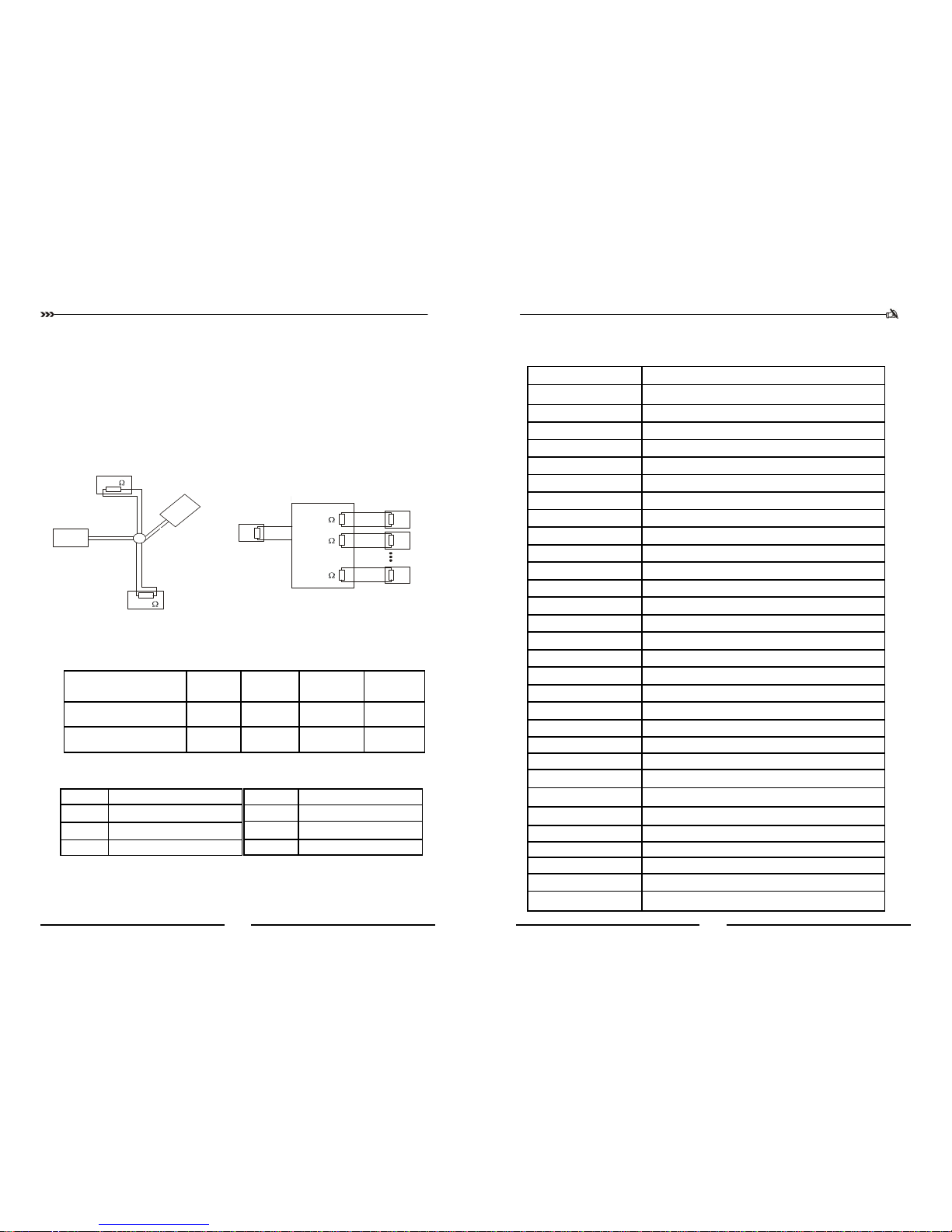
A. Bad connection of RS485.
B. One line of RS 485 is off .
C. Main machine is too far from dome.
D. Too many parallel connections.
A. Reconnect RS485;
B. Change another RS485;
C. Install a terminal matching
resistance;
D. Install a RS485 distributor.
Blurry picture
1. Focus of speed dome is in the manual
status.
2. Transparent lower dome gets dirty.
1. Change the manual focus status to
auto focus status. Or call the preset
to adjust the focus.
2. Clean transparent lower dome.
No self-testing ,or with
noise
Power supply not enough Replacement to meet the require-
ments of power
Mechanical failure Need to overhaul
There are the vertical
direction of the roll bar
on the monitor, when
switching between cam-
eras
Different phase of the camera power
If several speed dome camera is
connected to the same transformer,
the power supply connection in each
speed dome camera to be the same,
that is, the transformer at one end of
the outlet must be connected to the
terminal on the same side of each
speed dome camera
Control lines reversed or open circuit
Check the wiring of control lines, to
ensure that wiring is correct and
good contact
The address or protocol baud rate of the
speed dome camera is not set correctly Refer to the manual reset
The self-testing success-
fully but can not operate
high-speed dome camera
IR Intelligent Speed Dome Operation Manual ver2.0
9
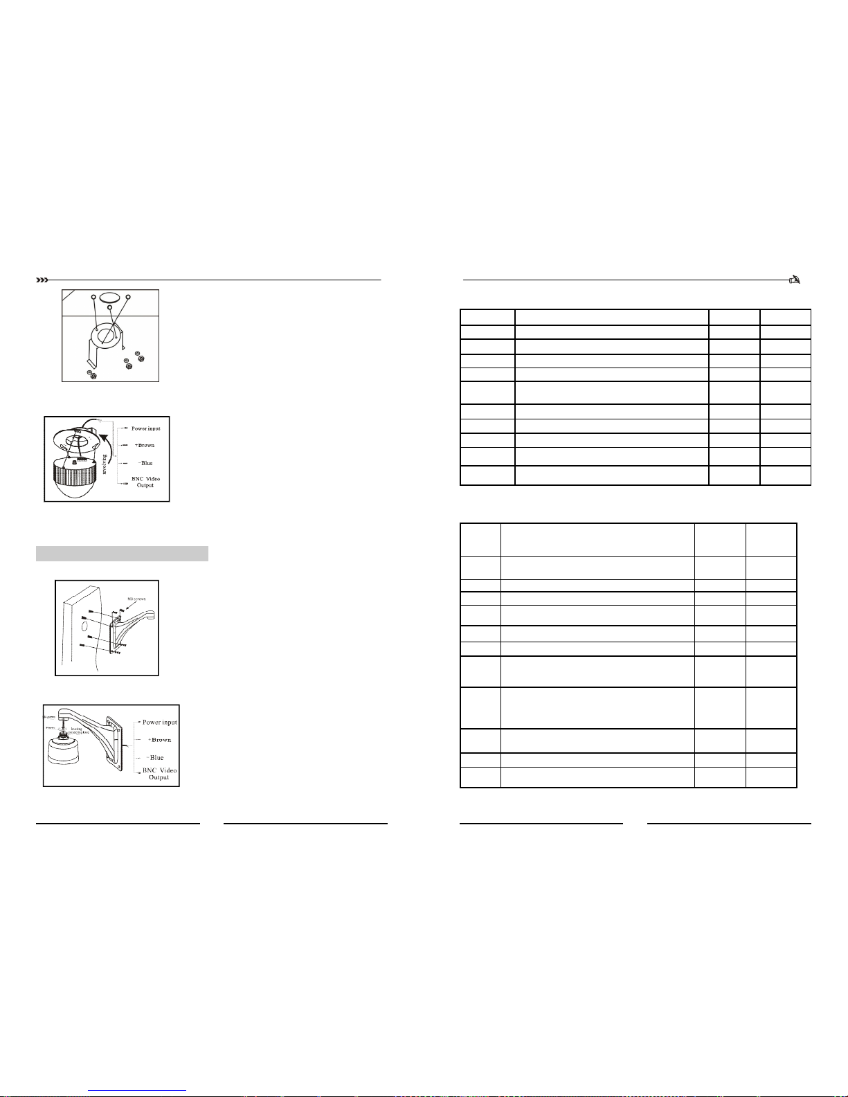
Step d. Connect dome lines
⑴ Put video line, power supply line and signal control line
through the round hole in the ceiling mount, and connect the
lines with the corresponding places in dome.( The type of
wire is shown as figure 5)
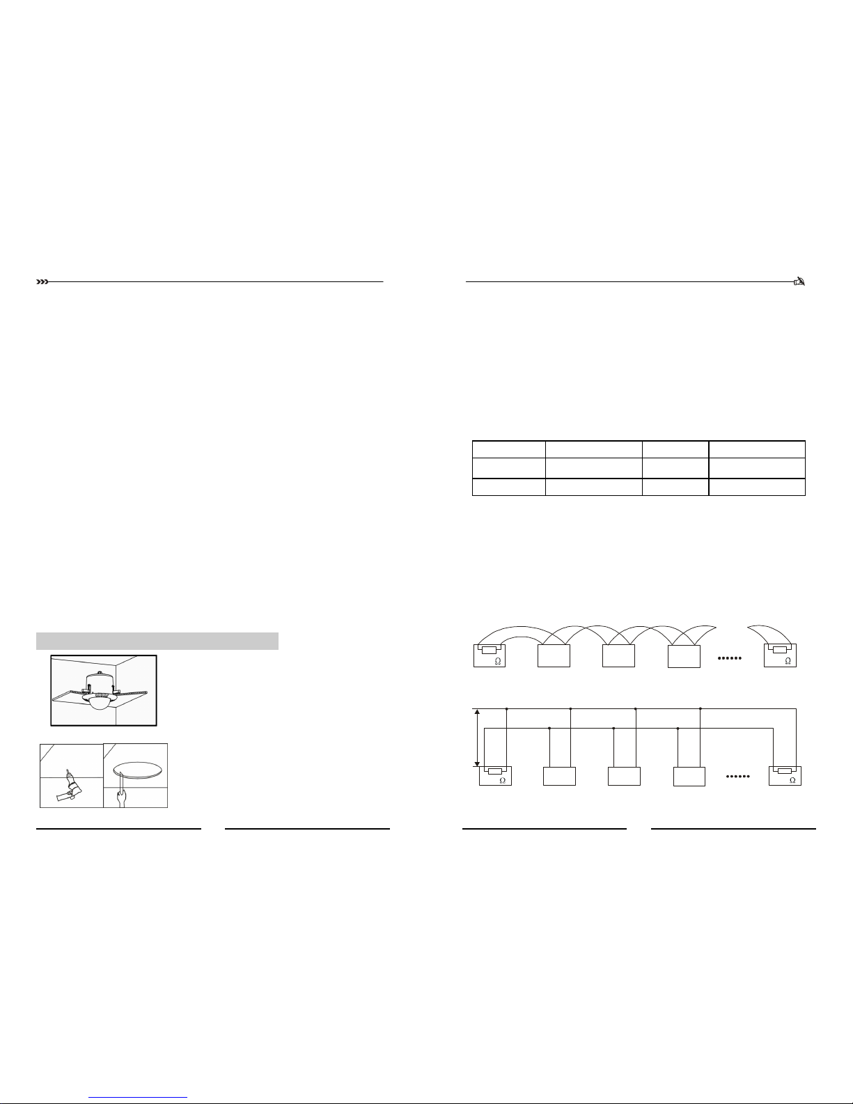
2、Ceiling-mounted installation :
Installation conditions:
This installation way is applied to stiff ceiling indoor
(1) The thickness of ceiling must be enough to set up the screws
(2) Ceiling must bear 4 times the weight of camera at least.
Step b. Install ceiling mount
(1) First, keep pushing the ceiling mount into the hole in the
ceiling until the mount is totally inside the hole. Second,
unfold the three brackets and screw them up. Last, when the
metal pieces are fully expanded, tighten the screws to fix the
mount into ceiling firmly.
Warning: A steel safe belt must be used between
ceiling mount and ceiling to avoid that speed dome
accidentally drops. Safe belt should be provided by
user .
Steps e. Dome installation
⑴ Insert the three screws which are in the bottom of dome into
the holes in ceiling mount, and then turn the mount as figure
5 shows to make sure that the screws are inside positioning
slot firmly.
Step a. drill a hole in the ceiling
(1) Draw a circle according to the size of hole with a pencil in
ceiling, and then remove the material inside the circuit.
(2) Drill three holes around the hole in the ceiling according to
the corresponding position in the mount and insert set-
screws in each hole. (Setscrews should be provided by
users).
figure(3)
figure(4)
figure(5)
figure(6)
figure(7)
Step c. Set speed dome
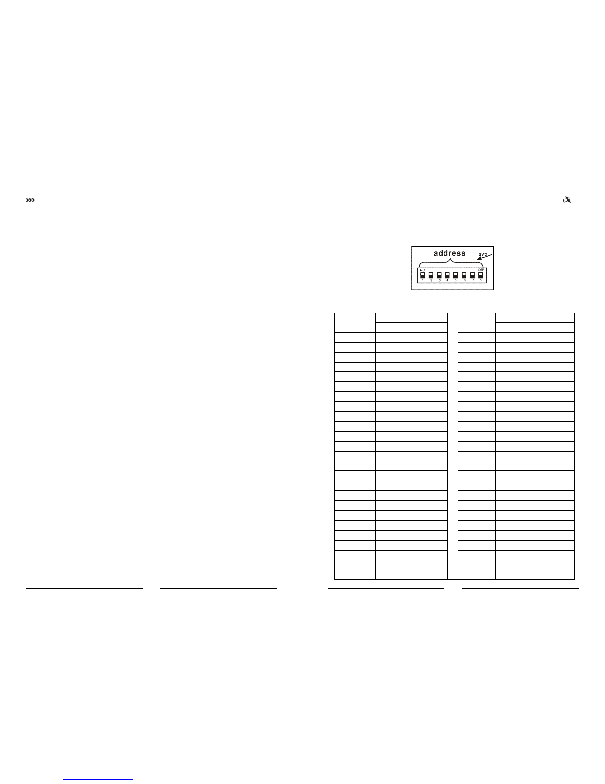
(1) Set (DIP switches) SW2 under the bottom of dome machine
to control speed dome IP address. (Detailed information can
be found in PART 12)
(2) Without SW2 DIP switcher , setting the IP address by soft-
ware address refer to Page21【Communication settings】