OWNERS MANUAL FOR MODEL A16314E rev 1
30 May 2016 Page 7
It is the owner’s responsibility to ensure that all-periodical
checks, necessary adjustments, services and repairs are
carried out.
STOP ENGINE - Never attempt any maintenance with the engine
running, remove spark plug lead and ensure the blades have
stopped rotating.
Before servicing, disconnect spark plug wire and ground it, disconnect
battery at negative terminal, to prevent accidental starting.
1. OIL CHANGING & FILTER REPLACEMENT (ENGINE): See Engine
Maintenance/Instructions Sheet and carry out as per Engine Manufacturers
Recommendations.
SERVICING ENGINE AIR CLEANER FOAM PRE-CLEANER—See
engine owners manual for correct method to check and service engine air
cleaner foam pre-cleaner.
2. LUBRICATION OF MACHINE: Lubrication of machine must be
carried out every 25 hours of operation or once a month, whichever occurs
first. More frequently when operated under adverse conditions.
A. OILING: A few drops of oil should be placed at the following
points: Steering linkage, disengaging linkages, height adjustment
mechanism, pivot bolt and linkages on clutch arm and clutch pedal.
B. CHAIN: Use only chain lube for lubrication of the drive and
steering chains.
C. GREASE POINTS: Grease nipples are located on top of the front
wheel stub axle.
Under no circumstances allow grease or oil to come into contact with
the Drive Cone or Clutch Plates. Should this problem occur, clean off
immediately with petrol whilst surface areas are cool and allow to dry
before operating machine.
3. TO CHECK BLADES: Stop engine. Remove spark plug lead. Side
Discharge Only, lift deflector and height adjustment control to highest
position. If necessary simply remove the blade bolt and nut using a
suitable spanner and replace worn parts.
4. ENGINE TO CLUTCH VEE BELT ADJUSTMENT: Loosen the four
engine mounting bolts. Move engine forward and adjust belt firmly.
Do not over tension belt. While maintaining tension on the engine
re-tighten bolts. Check belt tension at machine service period (25hrs)
or more frequently under heavy mowing conditions.
5. CLUTCH TO CUTTER VEE BELT ADJUSTMENT: Tension is
automatically adjusted by the belt tensioning springs.
6. CUTTER HEIGHT ADJUSTMENT: If the Mowing Attachment can
not be positioned to give a satisfactory grass cut height using the
available notches on the chassis the adjustable link can be used to
raise the Mowing Attachment to the desired height. Position the
mower on a smooth level surface and engage the mowing attachment,
lock the park brake on, and lower the Mowing Attachment to the
notch above the desired cut height. Place equal height spacers of the
desired height under the mowing attachment that can support the
mowing attachments weight and lower the Mowing Attachment onto
them. Loosen the 2 Screws located together on the front of the Rear
Link located below the front of the left foot rest. Push the Rear Link
rearwards until it stops and retighten the 2 screws. Adjust the rear
lifting link located on the middle rear of the mowing attachment by
tightening the nut until it just lifts the rear oif the mowing attachment
of the spacers. Lift the Mowing attachment off the spacers and
remove the spacers and check the cut height is as desired and the
deck is level to slightly higher (3—5 mm) at the back. Adjust height
again if required.
7. CUTTER BRAKE ADJUSTMENT: With disengagement handle in
engaged position and mowing attachment in low cut, normal clearance
between cutter head pulley and cutter head brake pad is
approximately 3mm (1/8"). To adjust clearance, remove 'R' pin from
brake pull rod, adjust to give required clearance, replace brake pull
rod and 'R' pin. Check operation after adjustment.
8. CLUTCH PLATE ADJUSTMENT: Periodically it will be found
necessary to adjust the clutch plates as the clutch cone wears. Carry
out this operation, with engine off and cutter in the engaged position.
Engage and disengage the cutter lever a few times and leave in the
engaged position, this will centre the clutch arm assembly into the neutral
position. Loosen the four square head set screws on the clutch plates
using tube spanner (AM006C1) and tommy bar (AM007). Insert the
clearance gauges supplied, one between the forward clutch plate and cone
and the other between the reverse clutch plate and cone and hook them
onto the intershaft. Slide both clutch plates against the clearance gauges
and clutch cone, tighten the set screws firmly onto the flat on the
intershaft. Remove gauges.
9. CUTTER DISENGAGING ADJUSTMENT: With the engine switched
off, engage the mowing attachment, then fully lower. Place a straight
edge vertically against the front of the front axle beam and in line with
the disengagement lever. Measure the distance between the straight
edge and the 8mm dia pin fitted with the small ‘R’ pin for the threaded
adjuster. Disengage mowing attachment and using the same method,
check the new distance. The difference should be 20 –22mm. Engage
mowing attachment, remove ‘R’ pin and adjust threaded adjuster
accordingly. Install ‘R’ pin and re-check measurement. Due to normal
wear in clutch to cutter vee belt, the cutter disengagement lever will
move lower and touch the foot rest. When this occurs the amount of
travel will need to be re-adjusted. If a new vee belt is installed the
above settings will apply.
Start engine and raise cutter to full height stop, cutter belt should not
engage. If this occurs switch off engine, engage cutter then screw
adjuster out 1 –2 turns then retest.
10. DRIVE CHAIN: Machines are fitted with automatic chain
adjusters. No adjustment is required. Replace chain when chain has
sagged enough to expose half the depth of the teeth on the bottom of
the large sprocket. Failure to replace worn chain will cause premature
wear of sprockets.
11. TO ADJUST STEERING CHAIN: Adjust chain by loosening the
four bolts which hold the steering idler shaft mounting brackets
(AM255) in position, slide forward to tension chain then retighten
bolts.
12. TO REMOVE MOWING ATTACHMENT: Fully lower mowing
attachment and engage, remove weight compensating spring, remove
'R' pin from rear lifting link and disconnect, remove ‘R’ pin from cutter
brake adjusting rod and disconnect, disengage mowing attachment,
remove belt, remove front pivot pin, Turn steering wheel to the left to
slide out mowing attachment. To refit, reverse the above.
13. TYRE PRESSURE: 140 Kpa (20.P.S.I.) approximately front and
rear. Uneven pressure can give an uneven finish when mowing and
may cause damage to tyres and/or tubes.
14. BATTERY MAINTENANCE: When not in use, a battery
discharges by as much as 1% a day, more when the climate is warm.
To make up for this loss, a boosting charge should be given once a
month. Disconnect battery terminals to charge, then allow to stand
minimum 1/2hr before re-connecting (re-check electrolyte level). If a
battery is not used for a period of more than three (3) months, the
terminals should be disconnected and trickle charged at two (2) amps
for two (2) hours once every three (3) months or before use.
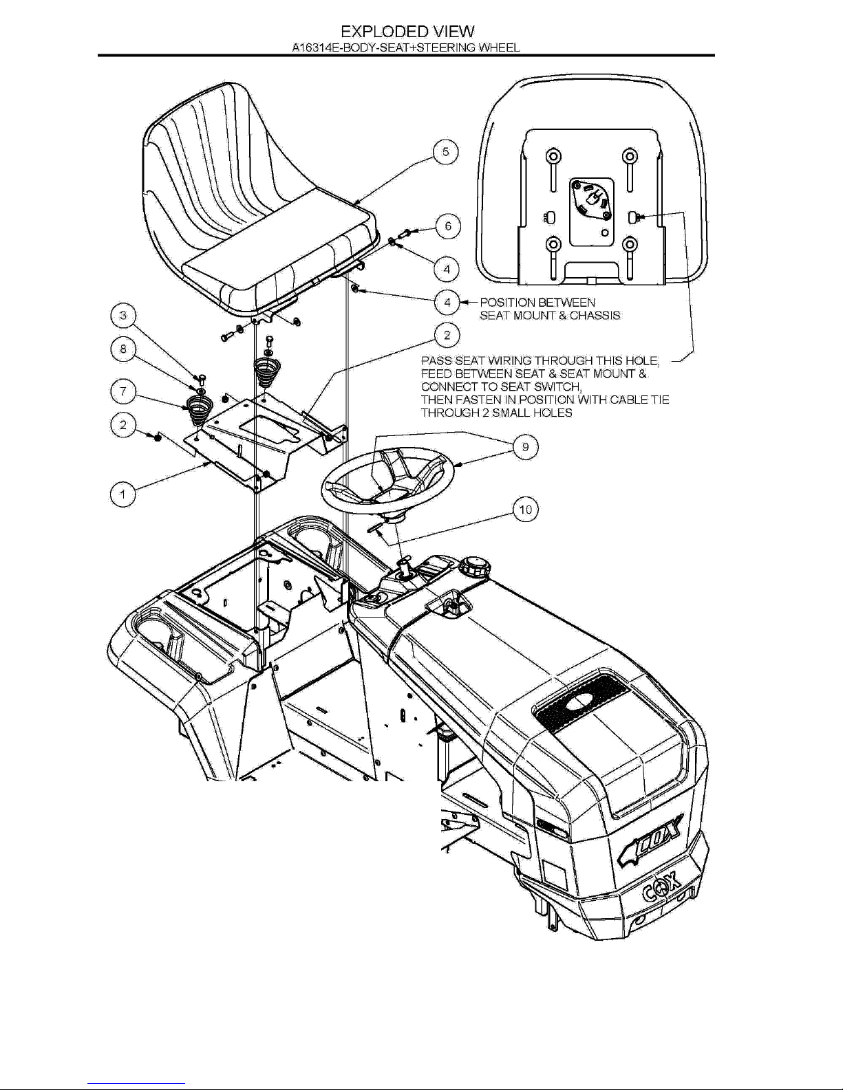
15. SEAT ADJUSTMENT: Loosen four seat mounting bolts and slide
seat into desired position in slots and re-tighten bolts.
16. REPLACE DRIVE CHAIN: Engage park brake, jack up rear of
machine, and remove L/H wheel. Push chain tensioner arms, one at a
time, away from chain and using a suitable spanner tighten pivot bolt
lock nuts to hold them out. Release park brake then turn rear axle to
bring chain into a suitable position for removal of the chain connecting
link. Remove connecting link and chain. Inspect both sprockets for
wear or damage, replace if necessary. Install new chain and
connecting link with the link clip between the wheel and chain.
Release pivot arm nuts until arm moves freely back to chain. Engage
park brake, install wheel and lower machine.
17. CLEANING AND POLISHING POLYETHYLENE BONNET AND
REAR MUDGUARD: To keep scratches on bonnet and mudguard to
minimum, do not rub or brush off with bare hands, use a soft cloth or
a light flow of compressed air. For dirt, wash with a steady stream of
water only (no detergent), then blow off excess water with air. To
polish remove excess dust or dirt. When surface is dry, spray on an
automotive type plastic preservative and leave on for 30 to 60
seconds. Using a dry soft cloth (i.e. cheesecloth) wipe off to bring up
lustre.
GENUINE SPARE PARTS: Always use Genuine Cox Factory Made
Spare Parts. Use of non-genuine COX spares will void your warranty.
SAFETY FIRST: The use of any mechanical device can cause injury if
incorrect procedures are used. Please ensure that all family members
of intended operators read safety section of this manual thoroughly.
TORQUE SETTINGS
1/4” UNC BOLT/NUT 10Nm (84lbf in)
5/16” UNC BOLT/NUT 20Nm (180lbf in)
3/8” UNC BOLT/NUT 36Nm (27lbf ft)
7/16” UNF BOLT 68Nm (50lbf ft)
6mm BOLT/NUT 9Nm (80lbf in)
20mm NUT 100Nm (74lbf ft)
5/8” UNF NUT 100Nm (74lbf ft)
MAINTENANCE INSTRUCTIONS