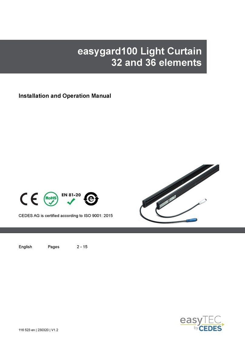
Cedes cegard/Mini User manual

CEDES
© CEDES Version 1.1 / 11th December 2008 Part No. 105 235
cegard/Mini
Light curtain for elevator doors
English
Deutsch
Français
Italiano
Español
Polski
IMPORTANT NOTE
FOLLOW THE INSTRUCTIONS GIVEN IN THIS MANUAL CAREFULLY. FAILURE TO DO
SO MAY CAUSE CUSTOMER COMPLAINTS AND SERIOUS CALL BACKS. KEEP IN-
STRUCTION MANUAL ON SITE.
Installation and Operation Manual
Bedienungsanleitung
Mode d’emploi
Manuale d’installazione e d’uso
Instrucciones de montaje y uso
Instrukcja obsługi
... accompanies you to the top

cegard/Mini Installation and Operation Manual
2 www.cedes.com © CEDES/December 2008
Languages
Pages
English............................................................................................................ 3 - 13
Deutsch ........................................................................................................ 14 - 24
Français........................................................................................................ 25 - 35
Italiano .......................................................................................................... 36 - 46
Español......................................................................................................... 47 - 57
Polski ............................................................................................................ 58 - 68
Declaration of conformity.................................................................................. 69
CSA certificate.................................................................................................... 70

Installation and Operation Manual cegard/Mini
© CEDES/December 2008 www.cedes.com 3
IMPORTANT NOTICE
WHEN THE CEGARD/MINI LIGHT CURTAIN IS USED AS A REPLACEMENT FOR ME-
CHANICAL SAFETY EDGES, IT IS THE RESPONSIBILITY OF THE INSTALLER TO EN-
SURE THAT ON COMPLETION, THE INSTALLATION COMPLIES WITH ALL THE RELE-
VANT STATE CODES, LOCAL CODES AND REGULATIONS THAT PERTAIN TO INFRA-
RED AND PHOTOELECTRIC DOOR PROTECTION DEVICES!
IN CANADA, PARTICULAR ATTENTION SHOULD BE GIVEN TO CLAUSES 2.13.5.1 AND
2.13.5.2 CAN/CSA-B44-B89!
CEGARD/MINI MUST BE INSTALLED ONLY BY AUTHORIZED AND FULLY TRAINED
PERSONNEL!
DO NOT USE THIS PRODUCT FOR THE PROTECTION OF DANGEROUS MACHINERY
OR IN EXPLOSIVE ATMOSPHERES OR RADIOACTIVE ENVIRONMENTS! USE ONLY
SPECIFIC AND APPROVED TYPES OF SAFETY DEVICES FOR SUCH APPLICATIONS,
OTHERWISE SERIOUS INJURY OR DEATH OF PERSONNEL MAY OCCUR!
Ex

cegard/Mini Installation and Operation Manual
4 www.cedes.com © CEDES/December 2008
Introduction
The infrared light curtain cegard/Mini consists of an
emitter (Tx) and a receiver (Rx) edge, both of which
have a built-in controller. These two active parts are
electrically connected directly to the door drive unit
of the elevator and mechanically mounted either to
the car door wings and/or to the slam post. There
are various types of optional mounting kits available
from CEDES. These kits are optimized to a specific
door drive or car type.
Functional description
The emitter and the receiver edge build up a grid of
infrared beams, which cover the door entrance to a
height of 1,800 mm (6 feet). The number of beams
covering the entrance area is dependent on the
model in use. The number after the product name
‘cegard/Mini’ indicates the length of the protection
field and the second number is the amount of active
opto elements. Due to the use of criss cross beams,
the number of active beams used for the door pro-
tection is higher than the number of elements.
When distance between emitter and receiveredges
is lower than approximately 800 mm the angled
beams are turned off.The emitter and the receiver
require a power supply of 14 to 30 VDC. The output
of the receiver is a push/pull (PNP/NPN) stage,
which is compatible with loads connected to the
positive as well as to negative power. The output
signal of the receiver can be inverted. No electrical
connection between the emitter and the receiver is
necessary because cegard/Mini uses an optical
synchronization principle. The protection field can be
reduced to 1,600 mm with a selector on the Emitter
edge.
If a power supply of 14 to 30 VDC is not available,
two different state-of-the art Power Supplies avail-
able from CEDES may be used.
A universal power supply with relay output and
integrated EMC filter accepts any voltage avail-
able from 17 to 265 VAC or DC without any
special wiring or adjustments. The polarity of
DC voltage is irrelevant. This product is espe-
cially useful in modernization applications where
the supply voltage is not standardized or known.
A simple power supply which accepts AC volt-
ages from 85 to 265 VAC or 120 to 375 VDC
with integrated EMC filter. This device has also
a relay output.
Main features of cegard/Mini
• Very robust and extremely compact design
• No earth connection necessary
• Designed lifetime of more than 20 years due to
- gold plated contacts
- special cable that withstands more than 20 mil-
lion door openings (if properly installed)
• Plug’n-play edges with integrated controller
• No link connection between emitter and receiver
due to optical synchronization principle
• Suitable for side or center opening doors
• Suitable for metal or glass doors
• Optimized for static installation
• Blanking of one defective opto element after 45
seconds (function not available in US and Cana-
dian versions)
• Mechanically compatible to cegard/Max and
MiniMax

Installation and Operation Manual cegard/Mini
© CEDES/December 2008 www.cedes.com 5
Muting function
If permanent blocking of a sensor element occurs,
cegard/Mini recognizes this as a defective or
blocked element. After 45 seconds, this particular
sensor element is blanked and no longer active (see
page 8, chapter 5). This function allows operation of
the device even with partial damage or blockage
due to vandalism. As soon as the blocked element is
free again it will be activated immediately.
Note: Blanking is not possible in certain
circumstances which are listed here. In the following
cases, blanking cannot be activated:
1. When the second element from the bottom is
defective (as the ‘synchronization’ beam, it is
essential for optical synchronization of all
others)
2. When the top or bottom element is defective
(blanking is not possible in order to comply with
the requirements of EN 81-70)
3. When there is more than one defective beam
(blanking is only possible when a single beam
is defective)
4. Blanking is not available in either the United
States or Canada
Installation
The installation should be done in the following
sequence:
1. Switch main power off and mark clearly
that this elevator is out of service
For your own safety, turn the power off before you
start working on the elevator! Clearly mark that this
elevator is out of service.
2. Mount the emitter and the receiver
The emitter and the receiver edge can be mounted
either to the door wings, to the door wing and the
slam post, or to a frame that is attached to the car.
The black “eyes” in the aluminum profile are the
optical elements which is the front of the edge. This
side has to “look” at its companion piece, which is
mounted on the opposite side of the cab door or
slam post.
Please note that the receiver (the one with the blue
connector) can be sensitive to "foreign" light. No
other source of external light, including the emitter of
any other light barrier system, should be directed
towards the receiver edge. Although cegard/Mini is
very tolerant of bright sunlight, it is better to mount
the receiver edge so that no sunlight shines directly
into the receiver lens. It is similar to human eyesight:
while you may have visibility even if looking directly
into the sun, it is harder to see clearly. Therefore, it
is always better to have the sun at your back!
Please note that objects smaller than the sensor
spacing may not be detected! In the USA and
Canada or for dynamic installations it is
recommended to use cegard/Mini with 32 elements.

cegard/Mini Installation and Operation Manual
6 www.cedes.com © CEDES/December 2008
Please observe the following mounting guidelines:
Never scratch or paint the optical lenses because they
form the light path! Do not drill additional holes into the
profile. Unpack them just before installation in order to
avoid damage!
40° 40°
The surface with the opto elememnts of the emitter and
the receiver should point to each other face-to-face!
Align the optical axis of the emitter and the receiver as
close as possible in order to achieve best performance
(±20° @ 2 m distance)!
Do not bend or twist the edges!
Oil may damage the cable. Contamination must there-
fore be avoided at all times!
☺
> 100'000 lux
Tx Rx
Tx Rx Rx Tx
Other light sources Other light sources
Tx Rx
Even if cegard/Mini is not affected by direct sunlight, it’s
better to avoid it.
Avoid external light from other infrared light sources like
photo eyes or light barriers!
Receiver (Rx) =
Blue connector
Emitter (Tx) =
White connector
For installation of opto edges please note:
Exit both cables, emitter and receiver, the same di-
rection
Do not bend the cables or expose them to tension
Ensure cables are kept as far as possible away
from AC mains or high voltages
Do not force, stretch or squeeze the cables
Ensure that the cable is well fastened and routed
Avoid soiling of opto edges
Avoid contamination by oil or greasy liquids
Avoid obstruction from door wings, cables etc. in the
protective area

Installation and Operation Manual cegard/Mini
© CEDES/December 2008 www.cedes.com 7
3. Guide the cables properly to prevent
damage
Guide the cables properly using appropriate
mounting material, e.g. cable protection tubes,
neoprene cable ties, cable guide wires (depending
on the type of mounting kit used).
If the cables are not properly fixed and
guided, their lifetime could be reduced
drastically. They can also be damaged due to
possible swing and snag in the hoistway! Always
follow the cable guide instructions carefully, which
can be found in the appropriate mounting kit
installation and operation manual.
4. Connect the emitter and the receiver
cables
Make sure that the power supply voltage available
for cegardMini is between 14 and 30 Volts DC. The
power supply has to provide at least 100 mA for
proper operation.
cegard/Mini meets all standards for resistance to
electromagnetic interference (EMI). However, it is
prudent to guard against interference.
Therefore, do not guide cegard/Mini connection
cables close to cables carrying high voltage and/or
high current. The cegard/Mini cables should also be
mounted as far away as possible from the door drive
motor or motor inverter (VVVF-drives) to avoid EMI
problems.
Receiver
Rx
Emitter
Tx
Fuse 0.5 A slow blow
GND
+14 ... 30 VDC
Power supply should be provided on site with an over-
current protecting fuse of max. 500 mA with "slow-
blow" tripping characteristics
Receiver (Rx) Connections
cegard/Mini on PNP or NPN load
USP
Out
0V
µC
NO/NC
Selector
Load
Load
NPN PNP
iNPN iPNP
Rx cable connection of the load
Brown: USP = +14 … 30 VDC
Blue: GND (0 V)
Black: Output (Door re-open signal)
White: NO/NC Selector
Rx cable connection for NO
Brown: USP = +14 … 30 VDC
Blue: GND (0 V)
Black: Output to door operator / elevator
controller
White: Selector connected to GND
Rx cable connection for NC
Brown: USP = +14 … 30 VDC
Blue: GND (0 V)
Black: Output to door operator / elevator
controller
White: Selector connected to USP or
not connected

cegard/Mini Installation and Operation Manual
8 www.cedes.com © CEDES/December 2008
Emitter (Tx) Connections
Highest beam 1822mm
Emitter/
Tx edge
Receiver/
Rx edge
Tx cable connection
for standard protection field heigth: 1,822mm
Brown: +14 … 30 VDC
Blue: GND (0 V)
Black: n.c
White: Height Selector not connected
or connected to GND (blue)
Highest beam 1582mm
Emitter/
Tx edge
Receiver/
Rx edge
Tx cable connection
for reduced protection field heigth: 1,582mm
Brown: +14 … 30 VDC
Blue: GND (0 V)
Black: n.c
White: Height Selector connected to USP (brown)
Application:
If there a parts in the door construction (e.g. doorcam)
which are moving through the protection field during
door closure certain elements of the light curtain have
to be disabled
Important:
1. This setting does not fulfill EN 81-70
2. Blanking function is not possible with reduced
protection field (see page 4)
5. Power-up and test for correct function
Turn on power after cegard/Mini has been correctly
installed. In each edge (Rx and Tx) there is one
optical indicator (green LED) which indicates the
light curtain status.
Edge LED Color LED ON LED OFF LED flasing
Rx Orange
Power OK
Object detected
No Power or
No object
1 element broken*
(Muting function, page 5)
Tx Green Power OK No Power -
* This blanking function is not available in the USA and in Canada. With one broken element system works with-
out criss cross beams

Installation and Operation Manual cegard/Mini
© CEDES/December 2008 www.cedes.com 9
6. Trouble shooting
If cegard/Mini does not operate as expected, ob-
serve the following trouble shooting guide step by
step:
1. Switch off the light curtain and then switch it on
again (Power-up for both the Rx and Tx edges)
2. Check supply voltage both on emitter and recei-
ver. Is the green indicator LED in the emitter
edge on and is the orange LED in the receiver
edge on when there are no obstacles between
the emitter and the receiver? Is the supply volta-
ge between 14 and 30 Volts DC? The ripple on
the DC voltage should not exceed more than
10% of the mean voltage within the min. and
max. range.
3. If the output of the receiver (black wire) is high
when the protected area is not obstructed, and in
this case it should be low, connect the white wire
of the receiver (Rx) cable to 0 V (blue wire, which
is also negative power, see page 8).
4. If the output of the receiver (black wire) is low
when the protected area is not obstructed, and in
this case it should be high, connect the white wi-
re of the receiver cable (Rx) to the positive power
(brown wire, see page 8).
5. If the output signal of the receiver is not stable
during the closing of the door, make sure that
a. there is not excessive EMI-noise generated by
the door drive or the door inverter or any other
means that is disturbing the door edge. In such
a case, move the cable of the receiver so that
the distance to the noise source is as wide as
possible. In addition, filter out the noise of the
source by using the optional relay module, the
optional power supply or the switching power
supply available from CEDES (connecting
diagram, page 12).
b. there are no obstacles between the emitter and
the receiver. Make sure that the door lock or
any other obstacle does not enter the light path.
c. the edges are properly installed and aligned so
that they cannot swing or vibrate and therefore
lose line of sight between themselves.
d. the optical elements of the edges are clean and
not full of dust or dirt. Although cegard/Mini is
very tolerant to this condition, its performance
is much better when it is clean.
6. If the doors are closing even with an obstacle1,
there are two possible reasons:
a. Output selector not properly set (see step 2
and 3)
b. Faulty / defective system wiring or defective
receiver edge2
1 Due to the nature of door system designs, (which as complete
systems is not fail safe), in extremely rare conditions doors can
close even with an obstacle present. Therefore, there must be, by
code, other safety means to prevent passengers from being hurt
by the elevator doors. These dangerous situations should and
can be detected by the elevator control, which should, in such a
case, take the elevator out of service.
Maintenance
Although cegard/Mini does not need periodical
maintenance, a functional check at least with every
elevator maintenance check is strongly
recommended. This periodic functional test should
consist of the following:
- Test the reopening function over the whole door
area. The door should reopen if an object is
placed anywhere between the sill and up to 1800
mm (standard configuration) above the sill.
- Clean the front surface with a soft towel from
dust or dirt. Especially when the door edges are
installed before the construction of the building is
finished (perhaps weekly during construction).
To clean the surface with a towel, it must be ei-
ther dry or slightly moist, but not wet.
- Confirm edges are fastened securely to the door
wings and slam post
- Confirm cables are routed properly as described
in the appropriate mounting kit installation in-
structions.
Important notices:
Never use any solvents, cleaners or mechanically
abrasive towels to clean the edge. The plastic lens
can be damaged!
Although the edges are water and weather resistant,
never use lots of water to clean the edges!
Never use high pressure water to clean the edges!
Do not scratch the surface when cleaning the edges!
Disregard of the mentioned precaution may lead to a
loss of safety!
Disposal
The light curtain should only be replaced if a similar
door protection device is installed. Disposal should
be done using the most up-to-date recycling tech-
nology according to local rules and laws. There are
no harmful materials used in the design and manu-
facture of the light curtain. Traces of such danger-
ous materials could be used in the electronic com-
ponents but not in quantities that are harmful to
health.
2This device (as well as all other door protection systems on the
market) cannot – by its nature – provide absolute safety for eleva-
tor passengers passing through the doorway. It must not be used
as the final fail safe device of the door mechanism. This ultimate
safety function has to be provided by a fail safe force and kinetic
energy limiter.

cegard/Mini Installation and Operation Manual
10 www.cedes.com © CEDES/December 2008
Technical Data
Supply voltage (USP) 14 ... 30 VDC
Ripple 10% of USP within the min/max limits
Supply current (@ 24 VDC) typ. 60 mA (protected on site by a "slow-blow" 0.5 A fuse)
Inrush current per edge < 2 A
Output type Semiconductor
Output polarity Push and pull (PNP and NPN)
Output logic NO and NC selectable
Output switching current max. 120 mA
Output switching capacity 100 nF
Number of optical elements 8, 16, 32
Number of beams up to 154 (32 Elements)
Response time (dependant of no. of elements) 25 ... 90 ms (60 ms for 16 elements)
Hold time < 200 ms
Power-up time < 2,000 ms
Operating range 0 ... 4 m
Protection height 1,800 mm (6 feet) or 1,582 mm (set by selector on Tx edge)
Dimensions 12 x 16 x 2,000 mm
First beam above lower end of edge 22 mm (0.78")
Max. ambient light (d.c. light) > 100,000 Lux
Enclosure rating IP65 / Nema 4
Temperature range -20 ... +65°C (-5 … 150°F)
Cable length 5 m, detachable, color coded
Cable lifetime 20 million door movements (if correctly installed)
Weight 0.3 kg
Accessories (not included in delivery)
see page 13
Relay Module,
Universal Power Supply 20 … 265 VAC / DC,
Switching power supply 85 ... 265 VAC, 120 … 375 VDC
Special configurations upon request

Installation and Operation Manual cegard/Mini
© CEDES/December 2008 www.cedes.com 11
Dimensions (all measurements in mm)
120
1,822
1,895
2
,
000
22
Blanked protection field
1,582 or 1,822
Distance between the elements
Connecting cable
Plug for emitter edge
(white)
Plug for receiver edge
(
blue
)
LED-Display
Uppermost element
Bottom element
7
1,717
847
Position of the mounting holes
Cross-section
Ø 4.6
Ø 5
16
8
12

cegard/Mini Installation and Operation Manual
12 www.cedes.com © CEDES/December 2008
Connection diagram for the cegard/Mini with CEDES switching power
supply (Part number 106 666)

Installation and Operation Manual cegard/Mini
© CEDES/December 2008 www.cedes.com 13
Accessories
Universal Power Supply Input Output
103 600
Power Supply for MiniMax or
cegard/Mini light curtain
20… 265 VAC / DC Voltage: 24 V ±10%
Relay: 250 VAC / 8 A
125 VDC / 0.5 A
30 VDC / 8 A
Switching power supply Input Output
106 666
Switching power supply for
sensors
85 .. 265 VAC
120 … 375 VDC
Voltage: 24 V ±10%
Relay: 125 VAC / 9 A
277 VAC / 7 A
30 VDC / 7 A
Mounting clip Material
103 738
Mounting clips 1.3-1.7mm sheet
(14 pcs)
Plastic PA, black
Mounting clamp Material
103 739
Byback MiniMax, cegard/Max,
metal clamp, 10 pcs.
Spring steel
Bypack with screws Material
104 420
14 pcs. Torx screw KA 3.5x32,
black
Steel, black
Relay module Input Output Relay
103 602
Interface module for sensors
with semi-conductor outputs
24 VDC ±15% Voltage: 24 V ± 10%
Relay: 12 A / 125 VAC
7 A / 30 VDC

cegard/Mini Bedienungsanleitung
14 www.cedes.com © CEDES/December 2008
WICHTIGER HINWEIS
FOLGEN SIE GENAU DEN ANWEISUNGEN IN DIESER ANLEITUNG. NICHTBEACHTEN
KANN KUNDENBESCHWERDEN HERVORRUFEN ODER RÜCKRUFMASSNAHMEN
AUSLÖSEN. BEWAHREN SIE DIESE ANLEITUNG BEI DER ANLAGE AUF.
WICHTIGE INFORMATIONEN
WIRD CEGARD/MINI ALS ERSATZ FÜR MECHANISCHE SICHERHEITSLEISTEN EINGE-
SETZT, LIEGT ES IN DER VERANTWORTLICHKEIT DES INSTALLATEURS, DASS DIE
MONTAGE MIT ALLEN RELEVANTEN NATIONALEN UND INTERNATIONALEN GESET-
ZEN UND VORSCHRIFTEN ÜBEREINSTIMMT, DIE INFRAROT- UND PHOTOELEKTRI-
SCHE TÜRSCHUTZVORRICHTUNGEN BETREFFEN.
IN KANADA MUSS FOLGENDEN VORSCHRIFTEN BESONDERE AUFMERKSAMKEIT
GESCHENKT WERDEN: 2.13.5.1 UND 2.13.5.2 CAN/CSA-B44-B89!
CEGARD/MINI DARF NUR VON AUTORISIERTEN UND GESCHULTEN PERSONEN IN-
STALLIERT WERDEN!
CEGARD/MINI DARF NICHT EINGESETZT WERDEN FÜR:
• DIE ABSICHERUNG VON GEFÄHRLICHEN MASCHINEN
• ANLAGEN IN EXPLOSIVER ATMOSPHÄRE
• ANLAGEN IN RADIOAKTIVER UMGEBUNG
FÜR SOLCHE ANWENDUNGEN DÜRFEN NUR DAFÜR SPEZIFIZIERTE UND FREIGEGE-
BENE SICHERHEITSPRODUKTE VERWENDET WERDEN, SONST KÖNNEN ERNSTHAF-
TE VERLETZUNGEN ODER DER TOD VON PERSONEN EINTRETEN.
Ex

Bedienungsanleitung cegard/Mini
© CEDES/December 2008 www.cedes.com 15
Einleitung
Der Infrarotlichtvorhang cegard/Mini besteht aus
einer Sender- (Tx) und einer Empfängerleiste (Rx)
mit jeweils einer eingebauten Steuerung. Diese bei-
den aktiven Teile sind elektrisch mit der Türsteue-
rung des Aufzugs verbunden und entweder an den
Türflügeln oder am Rahmen der Kabine montiert. Es
sind verschiedene Montagesätze von CEDES er-
hältlich. Diese Montagesätze sind jeweils für spezifi-
sche Tür- oder Kabinentypen optimiert.
Funktionsbeschreibung
Sender- und Empfängerleiste bilden zusammen ein
Gitter aus Infrarotstahlen, das die Türöffnung bis zu
einer Höhe von 1’800 mm überwacht. Die Anzahl
der Strahlen vor der Türöffnung ist abhängig von
dem jeweils verwendeten Modell. Die dem Produkt-
namen „cegard/Mini“ nachgestellte Nummer zeigt
die Länge des Schutzfeldes an, die zweite Nummer
entspricht der Anzahl der aktiven Optoelemente.
Aufgrund der Verwendung von Kreuzstrahlen ist die
Anzahl der zur Türüberwachung verwendeten akti-
ven Strahlen grösser als die Anzahl der Optoele-
mente.
Beträgt der Abstand zwischen Sender- und Emp-
fängerleiste weniger als ca. 800 mm, werden die
Schrägstrahlen abgeschaltet. Sender- und Empfän-
gerleiste erfordern eine Stromversorgung zwischen
14 und 30 VDC. Der Empfänger hat einen Push-
Pull-Ausgang (PNP/NPN), der eine Last ansteuern
kann, die an die positive oder negative Spannungs-
versorgung angeschlossen ist. Das Ausgangssignal
des Empfängers ist umkehrbar. cegard/Mini benötigt
keine elektrische Verbindung zwischen Sender- und
Empfängerleiste, da sich das System optisch syn-
chronisiert. Das Schutzfeld lässt sich mit einem Um-
schalter auf der Senderleiste auf eine Länge von
1’600 mm kürzen.
Ist keine Spannungsversorgung zwischen 14 und
30 VDC verfügbar, können zwei verschiedene Netz-
geräte von CEDES eingesetzt werden.
Ein Universalnetzgerät mit Ausgangsrelais und
integriertem EMV-Filter, das ohne spezielle
Verdrahtung oder Anpassungen für alle verfüg-
baren Spannungen zwischen 17 und 265 Volt
VAC oder VDC geeignet ist. Die Polarität der
Gleichspannung spielt keine Rolle. Dieses Pro-
dukt ist besonders für Modernisierungen geeig-
net, wo die Versorgungsspannung nicht stan-
dardisiert oder nicht bekannt ist.
Ein einfaches Netzgerät mit integriertem EMV-
Filter, das Wechselspannungen zwischen
85 und 265 VAC oder zwischen 120 und
375 VDC aufnimmt. Auch dieses Gerät verfügt
über ein Ausgangsrelais.
Hauptmerkmale von
cegard/Mini
• Sehr stabile und äusserst kompakte Konstruktion
• Keine Erdung erforderlich
• Lebensdauer von über 20 Jahren durch
- goldbeschichtete Kontakte
- Spezialkabel, das bei korrekter Montage über
20 Mio. Türöffnungen standhält
• Plug & Play-Leisten mit integrierter Steuerung
• Optische Synchronisation (keine Linkverbindung
zwischen Sender und Empfänger erforderlich)
• Für seitlich oder zentral öffnende Türen
• Für Metall- und Glastüren
• Optimiert für statischen Einbau
• Ausblenden eines defekten Optoelementes nach
45 Sekunden (Funktion nicht erhältlich in US und
Kanada)
• Mechanisch kompatibel zu cegard/Max und
MiniMax

cegard/Mini Bedienungsanleitung
16 www.cedes.com © CEDES/December 2008
Ausblendfunktion
Ist ein Sender- oder Empfängerelement permanent
blockiert, wird es von cegard/Mini als defekt oder
verdeckt erkannt. Nach 45 Sekunden wird dieses
Sensorelement ausgeblendet und ist nicht länger
aktiv (siehe Seite 19, Kapitel 5). Diese Funktion
erlaubt den Betrieb des Gerätes selbst bei teilweiser
Beschädigung oder Blockierung durch Vandalismus.
Ist ein zuvor blockiertes Element wieder frei, wird es
sofort wieder aktiviert.
Hinweis: Die Ausblendung ist in einigen
speziellen Fällen nicht möglich, die an dieser Stelle
kurz aufgelistet sind. In folgenden Fällen ist die
Ausblendfunktion nicht möglich:
1. Zweites Element von unten defekt
(Syncronisationsstrahl wird für die optische
Syncronisation benötigt)
2. Oberstes oder unterstes Element defekt
(Blanking nicht möglich zwecks Erfüllung der
Anforderungen gemäss EN 81-70)
3. Mehr als ein defektes Element
(Es wird nur maximal ein defektes Element zu-
gelassen)
4. Die Ausblendefunktion ist in den USA und Ka-
nada nicht erhältlich
Installation
Bitte installieren Sie cegard/Mini in der folgenden
Reihenfolge:
1.Hauptstromversorgung abschalten und
Aufzug eindeutig als „ausser Betrieb“
kennzeichnen
Schalten Sie zu Ihrer eigenen Sicherheit die Versor-
gungsspannung aus, bevor Sie mit der eigentlichen
Installation am Aufzug beginnen. Kennzeichnen Sie
den Aufzug eindeutig als „ausser Betrieb“.
2. Montieren von Sender- und Empfänger-
leiste
Die Sender- und die Empfängerleiste können ent-
weder an den Türflügeln, an einem Türflügel oder
dem Türpfosten oder an einem an der Kabine be-
festigten Rahmen montiert werden.
Die schwarzen „Augen“ im Aluminiumprofil sind die
optischen Elemente auf der Vorderseite der Leiste.
Diese Seite muss auf die Leiste, die auf der gegen-
überliegenden Seite des Kabinenzuganges ange-
ordnet ist, zeigen.
Es ist zu berücksichtigen, dass der Empfänger (Lei-
ste mit blauem Stecker) empfindlich gegen Fremd-
licht sein kann. Es dürfen keine Sender anderer
Lichtvorhänge, Sender von Lichtschranken oder
andere störende Lichtquellen in den Empfänger
strahlen. cegard/Mini ist zwar sehr unempfindlich
gegen helles Sonnenlicht, dennoch ist es besser,
die Empfängerleiste so zu montieren, dass kein
direktes Sonnenlicht auf die Empfängeroptik fällt. Es
ist ähnlich wie beim Menschen: Man kann zwar et-
was sehen, wenn man von der Sonne geblendet
wird, jedoch nur recht undeutlich. Daher ist es im-
mer besser, die Sonne im Rücken zu haben.
Bitte beachten Sie, dass Objekte, die kleiner als der
Abstand benachbarter Optoelemente sind, nicht
immer erkannt werden! In den USA und Kanada
sowie für dynamische Installation empfiehlt sich die
Verwendung von cegard/Mini mit 32 Elementen.

Bedienungsanleitung cegard/Mini
© CEDES/December 2008 www.cedes.com 17
Bitte beachten Sie ausserdem die folgenden Montagehinweise:
Nie die optischen Linsen zerkratzen oder anmalen, da
sie den Lichtstrahl bündeln! Keine zusätzlichen Löcher
in das Profil bohren. Erst kurz vor der Installation aus-
packen, um Beschädigungen zu vermeiden!
40° 40°
Die Oberflächen mit den Optoelementen des Senders
und des Empfängers müssen einander zugewandt
sein!
Für die beste Leistung richten Sie die optischen Ach-
sen der beiden Leisten so gut wie möglich aus
(±20° bei 2 m Entfernung)!
Leisten nicht verbiegen oder verdrehen!
Öl kann die Kabel zerstören! Eine Verschmutzung
muss jederzeit vermieden werden!
☺
> 100'000 lux
Tx Rx
Tx Rx Rx Tx
Andere Lichtquellen
A
ndere Licht
q
uellen
Tx Rx
Selbst wenn cegard/Mini nicht beeinträchtigt wird, ist
direkte Sonneneinstrahlung zu vermeiden.
Beeinflussungen durch andere Infrarot-Lichtquellen
wie Photozellen oder Lichtschranken verhindern!
Empfänger (Rx) =
blauer Stecker
Sender (Tx) =
weisser Stecker
Bei der Installation von Optoleisten bitte beachten:
Sender- und Empfängerkabel in gleicher Richtung
herausführen
Kabel nicht biegen, Zugspannung vermeiden
Kabel möglichst von Wechselstromnetzen
oder hohen Spannungen fern halten
Kabel nicht dehnen oder quetschen
Gute Befestigung und Führung des Kabels
sicherstellen
Verschmutzen der Optoleisten vermeiden
Verunreinigung mit Öl oder anderen
schmierenden Flüssigkeiten vermeiden
Behinderung durch Türflügel, Kabel usw. im
Schutzbereich vermeiden

cegard/Mini Bedienungsanleitung
18 www.cedes.com © CEDES/December 2008
3. Kabel richtig führen, um Beschädigungen
zu vermeiden
Damit die Kabel gut geführt sind, ist geeignetes
Montagematerial zu verwenden, z.B. Kabelschutz-
tüllen, Kabelbinder, Kabelschutzschläuche
(abhängig vom verwendeten Montageset).
Wenn die Kabel nicht sauber geführt und gut
fixiert werden, kann dies die Lebensdauer
erheblich verkürzen. Eine Zerstörung kann durch
Schwingen der Kabel und durch Einhängen im
Lichtschacht erfolgen! Die Montageanweisung für
die Kabel ist sorgfältig zu befolgen. Diese
Anweisung ist in der Montageanleitung des
entsprechenden Montagesets zu finden.
4. Anschluss der Sender- und Empfänger-
kabel
Stellen Sie sicher, dass die Versorgungsspannung
für cegard/Mini zwischen 14 und 30 VDC liegt. Für
einen einwandfreien Betrieb muss die Spannungs-
versorgung mindestens 100 mA liefern.
cegard/Mini erfüllt zwar sämtliche Normen hinsicht-
lich elektromagnetischer Störungen (EMV), ein
Schutz gegen Störungen ist dennoch zu empfehlen.
Führen Sie daher die Anschlusskabel des ce-
gard/Mini nicht zu nahe an Kabeln mit hoher Span-
nung oder hohem Strom entlang. Zudem sollten die
Kabel nicht zu nahe am Motor des Türantriebs re-
spektive am Leistungsteil der Türsteuerung (VVVF-
Antriebe) vorbeiführen.
Empfänger
Rx
Sender
Tx
träge Sicherung 0,5 A
GND
+14 ... 30 VDC
Die Spannungsversorgung muss vor Ort mit einer trä-
gen Sicherung von max. 500 mA abgesichert werden.
Empfänger(Rx)-Anschlüsse
PNP- / NPN- Anschlüsse
USP
Ausgang
0V
µC
NO / NC
Selektor
Last
Last
NPN PNP
iNPN iPNP
Rx-Lastanschluss
Braun: USP = +14 ... 30 VDC
Blau: GND (0 V)
Schwarz: Ausgang (Signal “Tür wieder öffnen”)
Weiss: NO/NC-Selektor
Rx-Kabelanschluss für NO
Braun: USP = +14 … 30 VDC
Blau: GND (0 V)
Schwarz: Ausgang an Türantrieb /
Aufzugsteuerung
Weiss: Selektor angeschlossen an GND
Rx-Kabelanschluss für NC
Braun: USP = +14 … 30 VDC
Blau: GND (0 V)
Schwarz: Ausgang an Türantrieb /
Aufzugsteuerung
Weiss: Selektor angeschlossen an USP oder
nicht angeschlossen

Bedienungsanleitung cegard/Mini
© CEDES/December 2008 www.cedes.com 19
Sender (Tx) Anschlüsse
Oberster Strahl 1‘822 mm
Sender/
Tx Leiste
Empfänger
/
Rx Leiste
Tx-Kabelanschluss
für Standardschutzfeldhöhe: 1’822 mm
Braun: +14 … 30 VDC
Blau: GND (0 V)
Schwarz: nicht verwendet
Weiss: Höhenumschalter nicht angeschlossen
oder angeschlossen an GND (blau)
Oberster Strahl 1‘582 mm
Sender/
Tx Leiste
Empfänger/
Rx Leiste
Tx-Kabelanschluss
für reduzierte Schutzfeldhöhe: 1’582 mm
Braun: +14 … 30 VDC
Blau: GND (0 V)
Schwarz: nicht verwendet
Weiss: Höhenumschalter angeschlossen
an USP (braun)
Anwendung:
Falls Teile der Türkonstruktion (z.B. Türschwert) sich
beim Schliessen der Tür durch das Schutzfeld bewegen,
sind bestimmte Elemente des Lichtvorhangs zu deakti-
vieren.
Wichtig:
1. Diese Einstellung entspricht nicht EN 81-70.
2.Die Ausblendfunktion funktioniert nicht, wenn das
Überwachungsfeld reduziert ist.
5. Einschalten und Funktionsprüfung
Nach der korrekten Installation des cegard/Mini
kann die Spannungsversorgung eingeschaltet
werden. In jeder Leiste (Rx und Tx) befindet sich
eine optische Anzeige (grüne LED) für den Lichtvor-
hangstatus.
Leiste LED-Farbe LED an LED aus LED blinkt
Rx orange Netzspannung OK
Objekt detektiert
keine Netzspannung oder
kein Objekt
1 Element defekt
(Ausblendfunktion Seite 16)
Tx grün Netzspannung OK keine Netzspannung -
* Diese Ausblendefunktion ist in den USA und Kanada nicht erhältlich. Bei einem defekten Element arbeitet das
System ohne Kreuzstrahlen.

cegard/Mini Bedienungsanleitung
20 www.cedes.com © CEDES/December 2008
6. Fehlersuche und -behebung
Sollte cegard/Mini wider Erwarten nicht korrekt funk-
tionieren, gehen Sie bitte die folgenden Schritte zur
Fehlersuche und -behebung Punkt für Punkt durch:
1. Schalten Sie den Lichtvorhang aus und wieder
ein (Power-up bei Rx- und Tx-Leiste)
2. Überprüfen Sie die Spannungsversorgung an
Sender und Empfänger. Leuchtet die grüne LED-
Anzeige an der Senderleiste und die orange
LED-Anzeige an der Empfängerleiste, wenn sich
kein Hindernis zwischen Sender und Empfänger
befindet? Liegt die Versorgungsspannung zwi-
schen 14 und 30 VDC? Die Restwelligkeit der
Gleichspannung sollte 10 % des Spannungs-
mittelwerts nicht überschreiten.
3. Ist das Ausgangssignal des Empfängers
(schwarzes Kabel) bei freiem Schutzfeld high,
obwohl es low sein sollte, so verbinden Sie den
weissen Draht des Empfänger (Rx)-Kabels mit
0 V (blaues Kabel, siehe Seite 19).
4. Ist das Ausgangssignal des Empfängers
(schwarzes Kabel) bei freiem Schutzfeld low,
obwohl es high sein sollte, so verbinden Sie den
weissen Draht des Empfänger(Rx)-Kabels mit
Plus (braunes Kabel, siehe Seite 19).
5. Ist das Ausgangssignal während der Tür-
schliessung nicht stabil, stellen Sie sicher dass:
a. keine übermässigen EMV-Störungen vom Tür-
antrieb, der Türsteuerung oder anderen Gerä-
ten, die übermässige Störungen erzeugen, vor-
handen sind. Sollte dies dennoch der Fall sein,
führen Sie die Anschlusskabel der Optoleisten
so weit wie möglich weg von der Störquelle. Zu-
sätzlich können Störungen z.B. mit dem Relais-
modul oder mit dem universellen Netzteil von
CEDES unterdrückt werden (siehe Seite 23).
b. sich keine Hindernisse zwischen Sender und
Empfänger befinden. Weder die Türverriegelung
noch andere Gegenstände dürfen in die Licht-
strecke ragen.
c. die Leisten richtig montiert sind, so dass sie
nicht schwingen oder vibrieren und dadurch
nicht mehr richtig ausgerichtet sind.
d. die optischen Elemente der Leisten sauber sind
(kein Staub oder Schmutz). Obwohl cegard/Mini
gegenüber Verschmutzungen nicht sehr emp-
findlich ist, ist die Leistung mit sauberen Leisten
entsprechend besser.
6. Es kann zwei Gründe geben, wenn sich die Tür
trotz eines Objekts1im Türbereich schliesst:
a. Anschluss „Selektor“ nicht richtig ange-
schlossen (siehe Schritte 2 und 3)
b. Fehlerhaft verdrahtete oder defekte Empfänger-
leiste2
1 Türsysteme und deren Schutzeinrichtungen für Aufzüge sind
aufgrund ihrer Bauart keine ausfallsicheren Systeme. Somit kann
auch nicht jeder Fehler im cegard/Mini, in der Verbindung von
cegard/Mini zur Türsteuerung oder in der Türsteuerung erkannt
werden. Solche Fehler muss die Tür- oder Aufzugssteuerung
erkennen und entsprechende Sicherheitsmassnahmen wie Stille-
gung des Aufzugs einleiten.
Unterhalt
Obgleich cegard/Mini keine periodische Wartung
benötigt, wird eine Funktionsprüfung mindestens mit
jeder Aufzugswartung oder alle sechs Monate sehr
empfohlen. Diese periodische Funktionsprüfung
sollte folgendes enthalten:
- Prüfen Sie die Funktionsfähigkeit über den gan-
zen Türbereich. Die Tür sollte sich öffnen, wenn
ein Gegenstand zwischen Türschwelle und bis
1’800 mm über der Türschwelle (Standardein-
stellung) in das Lichtfeld gebracht wird.
- Entfernen Sie mit einem weichen Lappen Staub
und Schmutz von den Frontflächen der Optolei-
sten. Dies ist insbesondere zu beachten, wenn
das Gebäude noch im Bau ist und sehr viel
Staub erzeugt wird; in diesem Falle empfiehlt
sich eine wöchentliche Reinigung. Der Lappen
für die Reinigung muss trocken oder feucht sein,
jedoch keinesfalls nass.
- Überprüfen Sie, ob die Leisten gut montiert sind
und fest sitzen.
- Überprüfen Sie, ob die Kabel richtig verlegt sind,
wie das in den Montageunterlagen des entspre-
chenden Montagesatzes beschrieben.
Wichtige Hinweise:
Benutzen Sie niemals Lösungs- oder Reinigungs-
mittel oder scheuernde Tücher. Die Kunststofflinse
könnte zerstört werden!
Obschon die Leisten wasser- und witterungs-
beständig sind, benutzen Sie niemals grosse Men-
gen von Flüssigkeit für die Reinigung!
Niemals darf ein Hochdruckreiniger verwendet wer-
den! Beim Reinigen nie die Oberfläche verkratzen!
Missachtung der oben genannten Punkte kann zu
einem Verlust der Sicherheit führen!
Entsorgung
Der Lichtvorhang darf nur ersetzt werden, wenn eine
ähnliche Türschutzvorrichtung angebracht wird. Die
Entsorgung muss gemäss den neuesten bekannten
Recyclingtechnologien und entsprechend den loka-
len Bestimmungen und Vorschriften erfolgen. Der
Lichtvorhang enthält keine schädlichen Materialien.
Auch in der Fertigung kommen keine schädlichen
Materialien zum Einsatz. Spuren von schädlichen
Stoffen können in den elektronischen Bauteilen vor-
kommen, jedoch nicht in gesundheitsschädlichen
Mengen.
2cegard/Mini (wie auch alle anderen auf dem Markt erhältlichen
Türabsicherungssysteme) kann keine absolute Sicherheit für
Aufzugspassagiere bieten. cegard/Mini darf nicht als fehlersiche-
res System eingesetzt werden. Es sind gemäss den nationalen
und internationalen Vorschriften Schliesskraftbegrenzer und
Begrenzer der kinetischen Energie zu verwenden.
Table of contents
Languages:
Other Cedes Light Fixture manuals