PacLights FHUS Series User manual

INSTALLATION GUIDE FHUS Series LED High Bay
Instructions and specifications are subject to change at any time without notice. Copyright© 2020 PacLights All Rights Reserved Page 1 of 3
Need help? (800) 988 -6386 Email: CS@PacLights.com Website: www.PacLights.com
02-00044-200818
FHUS HOOK MOUNT
IMPORTANT
READ CAREFULLY BEFORE INSTALLING FIXTURE. RETAIN THESE INSTRUCTIONS FOR FUTURE REFERENCE.
PacLights fixtures must be wired in accordance with the National Electrical Code and all applicable local codes. Proper grounding is required for safety.
THIS PRODUCT MUST BE INSTALLED IN ACCORDANCE WITH THE APPLICABLE INSTALLATION CODE BY A PERSON FAMILIAR
WITH THE CONSTRUCTION AND OPERATION OF THE PRODUCT AND THE HAZARDS INVOLVED.
WARNINGS:
• Make certain power is OFF before installing or maintaining fixture. No user serviceable parts inside.
• To prevent wiring damage or abrasion, do not expose wiring to edges of sharp objects.
CAUTION:
• For proper weatherproof function all gaskets must be seated properly and all screws inserted and tightened firmly. Apply weatherproof silicone
sealant around the edge of the Back Box and/or Junction Box. This is especially important with an uneven wall surface. Silicone all plugs and
unused conduit entries.
FIG.1
FHUS 3/4” CONDUIT PENDANT MOUNT
FIG.3
FHUS 060/080/100/120/150 (Universal or 480v) FHUS 200/250 (Universal or 480v)
The Hook Mount can be used to hang the FHUS to a desired
height. Remove the Trunnion Mount by removing the Bracket
Screws. Loosen the Set Screw to install the Hook Mount. Screw
the Hook Mount into the top of the FHUS fixture. Tighten the Set
Screw to hold the Hook Mount in place.
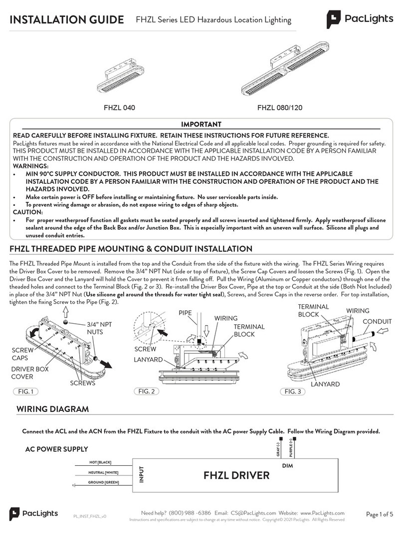
Connect the ACL and the ACN from the FHUS Fixture to the conduit with the AC power Supply Cable. Follow the Wiring Diagram provided.
AC POWER SUPPLY
FHUS DRIVER
GRAY (-)
PURPLE (+)
HOT [BLACK]
NEUTRAL [WHITE]
GROUND [GREEN]
WIRING DIAGRAM
DIM
INPUT
FHUS HOOK MOUNT
SET
SCREW
The 3/4’ NPT Conduit Pendant Mount can be used to hang the
FHUS fixture from a conduit. Install by screwing the Pendant
Mount into the top of the FHUS Fixture. Attach the Power and
Dim Cables to the appropriate entries of the Pendant Mount
Housing. Note: FHUS HV 200 & 250 have a specific Pendant
Mount Adapter. Refer to FIG 1. for Trunnion Mount Removal.
FHUS PENDANT
MOUNT
PENDANT MOUNT
ADAPTER (for HV Models)
FIG.4
CONDUIT
POWER
CABLE
DIM
CABLE
FHUS FIXTURE
FHUS TRUNNION
MOUNT
SCREWS
FIG.2

INSTALLATION GUIDE FHUS Series LED High Bay
Instructions and specifications are subject to change at any time without notice. Copyright© 2020 PacLights All Rights Reserved Page 2 of 3
Need help? (800) 988 -6386 Email: CS@PacLights.com Website: www.PacLights.com
02-00044-200818
The Bi-Level Dimming control provides energy eciency for the
FHUS Fixture.The Bi-Level Dimming control features an occupancy
sensor, a timer, three step dimming switches, and a photo sensor. The
Optional Wireless Deployment Device is used to adjust the settings
of the dimming control on the FHUS fixture.
WIRELESS DEPLOYMENT DEVICE FHUS 90° PRISMATIC REFLECTOR (OPTIONAL)
FIG. 5
The 90° Prismatic Reflector provides focused lighting and prevents
over spill. The Prismatic Reflector is easy to install. Place the Screws
(4 provided) through the holes in the Reflector and screw in through
the four holes in the lens rim to the FHUS Fixture.
FIG. 8
WIRELESS DEPLOYMENT
DEVICE
FIG. 9
ON/OFF
Turn on or turn o the Wireless Deployment Device.
MW/PIR
Toggle from the microwave sensor function to PIR sensor
function. ALWAYS select MW for this contol.
Scene
Press the button to change from the dierent scene options,
daylight threshhold disabled.
Start
Press the button before choosing the parameters; or press it for
10 seconds, it will be RESET function.
Memory
Press the button after choosing all the parameters to save them.
Apply
Press the button to deliver the saved settings to the other sensors
directly.
Hold Time
The period of light keeping 100% brightness after moving objects
leave the detection area.
Stand-by-period
The period of light keeping low output before it gets completely
o. When it’s preset as --, the light always keep at low output
even when no movement in the detection area.
Power %
Press the button to change the output power from 0% to 100%, it
changes 5% every press.
Test (2s)
The button “Tests (2s)” is for testing purpose after commissioning.
Pressing this button, the sensor goes to test mode (hold time is
only 2s).
Dalight Threshhold
Definition of the ambient brightness; only when the ambient
brightness is lower than the preset specific lux amount, the sensor
will work; when it’s preset as “disable”, the sensor works everytime
it detects motion regardless of the ambient lux level.
Detection Area
The area in which movement will trigger the sensor, 100%
detection area also means strong sensitivity.
Standy-by dimming level
The definition of low output during the standby period.
Increase or decrease paramters.
Start Memory Apply
MW/PIR Scene
+
%
POWER
(2S)
Test
SCREWS
MW/PIR
Scene
Start
Memory
Apply
%
POWER
(2S)
Test
+
FHUS PRISMATIC DROP LENS (OPTIONAL)
The Prismatic Drop Lens provides glare control. The Prismatic Drop
Lens requires a Prismatic Reflector to attached to. Installation to the
Prismatic Reflector is simple. Place the Ring around the rims of the
Prismatic Reflector and Drop Lens and then pull the Spring around
and attach to the latch on the Ring.
PRISMATIC
REFLECTOR
FIG. 6
FIG. 7
FHUS
FIXTURE
FHUS
FIXTURE
DROP LENS
HOLD
SPRING
PRISMATIC
REFLECTOR
RIMS
RING
LATCH
FIG. 10
RING
HOLD
SPRING

INSTALLATION GUIDE FHUS Series LED High Bay
Instructions and specifications are subject to change at any time without notice. Copyright© 2020 PacLights All Rights Reserved Page 3 of 3
Need help? (800) 988 -6386 Email: CS@PacLights.com Website: www.PacLights.com
02-00044-200818
FHUS TRUNNION MOUNT
The FHUS Trunnion Mount is included and attached to the FHUS
Fixture. The FHUS Trunnion Mount is a surface mount bracket that
can be used to surface mount the FHUS fixture.
1
2
FIG. 11
FHUS FIXTURE
FHUS TRUNNION
MOUNT
FIG. 13
Instead of having the fixture directly surface mounted to a fixed
position, the FHUS fixture can be adjusted by loosening the screws
at the sides of the of the Trunnion Mount. Rotate the FHUS Fixture
to the desired tilt angle to aim at a specific position. Tighten the
screws to firmly tighten the FHUS Fixture to the Trunnion Mount
(Mounting Bolts not included).
5
FIG. 15
Fasten the TRUNNION MOUNT, with the FHUS Fixture, to the
mounting surface (Wall or Ceiling) with the appropriate bolts by a
certified personnel and may vary depending on the mounting surface
(Mounting Bolts not included).
4
FIG. 12
TRUNNION MOUNT DIMENSIONS
3
FIG. 14
FHUS FIXTURE
WALL / CEILING
FHUS FIXTURE
FHUS 060-150 TRUNNION
MOUNTS
FHUS 200 & 250 TRUNNION
MOUNTS
BOLTS
TRUNNION MOUNT
TRUNNION
MOUNT
WALL / CEILING
SCREW
BRACKET
This manual suits for next models
7
Other PacLights Light Fixture manuals
Popular Light Fixture manuals by other brands

smart & green
smart & green C-LITE quick start guide

Awex
Awex TWINS T5 8W Assembly instructions

Elation
Elation Platinum Wash ZFX Pro XL user guide

Elation
Elation ELAR DW BRICK instruction manual

Kichler Lighting
Kichler Lighting 16140SS30 instructions

Triarch
Triarch Semi Flush 31601-16 2lts Assembling instructions