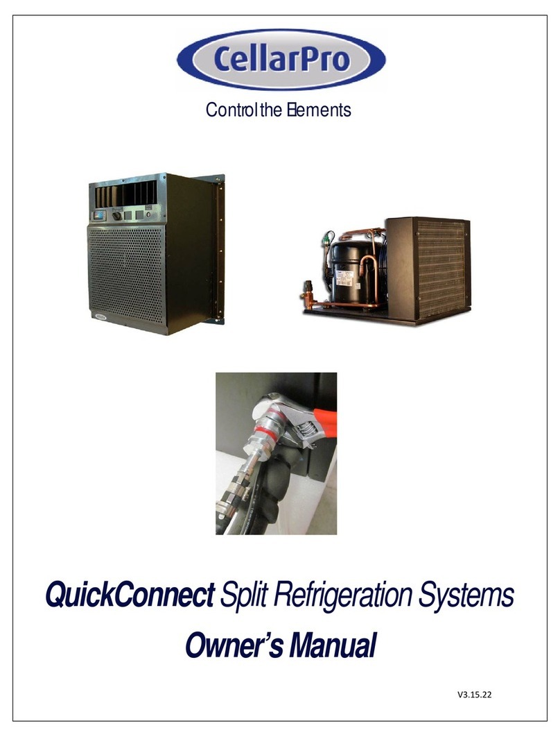
CellarPro AH12S Series User manual

V1.20
CellarPro
Large Air Handler
Split Systems
AH12Sx, AH18Sx, AH24Sx
Residential & Commercial
1445 N. McDowell Blvd, Petaluma, CA, 94954
877.726.8496 www.cellarpro.com
Outdoor Condensing Unit
Evaporator

V12.21
2
This page intentionally left blank.

V12.21
3
Product Nomenclature
AH
-
24
-
Sx
Model
AH
=
Air Handler
Nominal Cooling Capacity (BTUH at 55°F Cellar Temp)
12
=
12,400 / 1.25 Ton
18
=
15,500 / 1.50 Ton
24
=
18,200 / 2.00 Ton
Configuration
Sx
=
S = Split System with Remote Condensing Unit
x = Designed for Interior or Exterior Exposure

V12.21
4
Our Large Air Handler cooling systems use a common approach to optimize compressor size, fin spacing
and coil size, and blower air fan. The goal is to maximize cooling power without stripping humidity and
maintain consistent temperatures.
Our Large Air Handlers offer a wide array of modifications, such as a networkable controller, integrated
humidifier and integrated heater.
Evaporator Housing
The housing is manufactured from aluminum for light weight, corrosion resistance and aesthetics. The
cabinet is structurally reinforced throughout to provide a stable and secure platform for the components.
The evaporator section is insulated for thermal efficiency. Panels are fastened with quick release hardware
to simplify internal access.
Evaporator Coils
The unit has a large-face A-Frame coil for increased cooling efficiency and efficient power usage. The copper
tube + aluminum fin evaporator coils are mounted in a stainless steel condensate pan with a condensate
safety switch to guard against condensate overflow. Commercial-grade Electrofin coating protects the
evaporator coil from leaks and corrosion.
Blower and Blower Motor
Our Large Air Handler units incorporate a blower and motor in a draw-thru configuration for even air
distribution across the coils. The large blower runs at low RPM that minimizes noise and motor horsepower
consumption. The blower assembly is mounted to an internal chamber to further reduce noise levels.
Electrical System
The electrical system features a Class 2, 24 VAC control circuit, and includes all
required contactors, fuses and/or circuit breakers. Field connections (24 VAC)
and high voltage connections are provided through separate terminal blocks in
the electric box. A defrost controller is mounted to the unit and manages defrost
cycles, freeze protection and high/low temperature alarms. The temperature
control circuit is compatible with standard or networkable 24 VAC thermostats.
Standard Design Features

V12.21
5
Refrigeration System Components
Easily accessible components in the Evaporator include: thermal expansion valve, pump-down solenoid
valve, suction line service access port, and condensate overflow emergency shut-off float switch.
Condensing Unit components include an electronic controller for low pressure control cut-in/cut-out
adjustment, mounted filter drier and sight glass, and liquid/suction service valves.
All units are evacuated and charged with dry nitrogen prior to shipment. Two dedicated power supplies
are required, one to the evaporator and one to the condensing unit. No communication wiring is
required between the Evaporator and the Condensing Unit. The Condensing Unit enclosure is suitable
for indoor or outdoor installations.
Without the optional Integrated Humidifier, the Evaporator operating range is 45°F to 62°F cellar
temperature. With the Integrated Humidifier, the Evaporator operating range is 51°F to 62°F. In addition
to managing the defrost cycle, the defrost controller is programmed to ensure that the cellar does not
drop below the minimum allowable temperature. The defrost cycle is time initiated, temperature
terminated, with a factory default of 1 hour, field adjustable in one-hour increments. If defrost is not
required, the system will terminate the defrost and return to refrigeration automatically after a 3-minute
delay.
Compressor
All systems incorporate scroll compressors for high reliability, high efficiency and
low noise. Compressors are mounted on vibration isolators to minimize noise
transmission to the cabinet.
Evaporator Ducting
Flanges are provided on the Evaporator air intake and exhaust plenums for easy attachment of ducting.
Using 14" diameter R-6 insulated flex ducting, the Evaporator can be ducted up to 100 equivalent feet (50
equivalent feet per duct). Using R-6 insulated hard ducting, the Evaporator can be ducted with maximum
external static pressure of 0.3"wg and minimum cross sectional area of 153 sq inches. Units are rated to
0.30”wg external static pressure. All ducting must be insulated to R-6 minimum.
The condensing unit cannot be ducted.
Evaporator Air Filter –FOR NON-DUCTED INSTALLATIONS ONLY
We provide a Merv 5 air filter measuring 12”x25”x1” for the Evaporator cold air intake. The purpose of the
filter is to keep the evaporator fins free of debris; it is not an air quality filter. This filter is for non-ducted
operation only. If the Evaporator is ducted, the filter must not be installed at the unit.
To use a filter in a ducted application, the filter size must be increased to offset the duct pressure loss
from the filter. In a ducted application, the filter must be at least 2.6 ft^2 (approx. 16”x24”), 1” deep
maximum, non-pleated, and Merv 5 or less.

V12.21
6
Options & Upgrades
Electrode Canister Humidifier
We offer an integrated Electrode Canister humidifier inside the cooling unit that
provides humidification and allows you to maintain ideal humidity conditions inside
the cellar. The humidifier senses cylinder current draw, automatically flushing and
filling the cylinder to control the mineral content of the water and humidity output.
The output is field adjustable from 1 to 5 lbs/hr. A “Change Cylinder” light alerts
service personnel when the humidifier requires service.
The humidifier must be connected to a water line. When a humidifier is purchased,
we provide a 1/4” water supply shut off ball valve which is mounted on the exterior
of the cabinet housing.
A dedicated Humidistat is included with the humidifier, because most 24VAC
thermostats will only allow humidity control up to 50%RH. The Humidistat must be
installed inside the cellar near the return airflow in an area with good air circulation.
The Humidistat controls the humidity from 5% to 70%RH in 5% increments. The
humidistat controls only humidity and is not Internet accessible.
Electric Heat
For wine cellars that are exposed to conditions below 55°F temperatures, CellarPro
Air Handlers can be configured with optional integrated heaters to provide 3kW
(10236 BTUH) of heat. The unit incorporates a factory installed nichrome wire
heater. The heater has low voltage thermal safety cutouts with automatic reset and
a second power line fuse link (over-temperature) safety device.
Internal Condensate Pump
We offer an integrated condensate pump that will be mounted in the evaporator
drain pan. This option includes 25ft of 1/4”ID PVC drain line. In the event that the
condensate pump cannot remove the water fast enough, the emergency shut-off
float switch (included as standard equipment) locks out the compressor until the
condensate pump has emptied the drain pan.

V12.21
7
Ecobee Networkable Thermostat
The cooling unit is compatible with most 24V Networkable
Thermostats (sold separately).
We offer the Ecobee SmartThermostat Pro (P/N 31453)
which incorporates temperature control and humidity
display in an attractive, backlit, easy to install wall-
mounted unit.
Features include:
Internet connectivity for monitoring, management
and configuration of the thermostat
Set up alerts and service reminders, including air
filter monitor, over or under temperature, high
humidity, or customer selected contact closure
Displays the cellar humidity from 5% to 95%
Voice recognition through Amazon's Alexa
Personalized web portal and smart phone apps
available
Simple program editing and preferences
Manage vacations and building shutdowns
Full color 3.5" LCD display
Energy Star and FCC Class B Compliant
Adjustable differential
Compressor short cycle protection
E-Mail or Text Messaging
View reports how cooling unit is performing
Manage multiple thermostats from 1 web portal -
no annual fee

V12.21
8
System Airflows
Hot Air Exhaust
Cold Air
Intake
(From Cellar)
Cold Air Exhaust
(To Cellar)
Fresh Air
Intake
Rear and
Left Side
Condensing Unit
Evaporator
(Front)
System Specifications

V12.21
9
Evaporator Cut Sheet
Evaporator Piping Connections

V12.21
10
Evaporator Wiring Diagram AH12-24Sx

V12.21
11
Condensing Unit Cut Sheet
DIMENSIONS IN INCHES

V12.21
12
Condensing Unit Wiring Diagram AH12-24Sx

V12.21
13
AH12-24Sx Evaporator Power Supply Requirements
Fan Only Fan / Humid Fan / Heater
Fan / Humid /
Heater
Model
Power
Supply
FLA W FLA W FLA W MCA
Max
Fuse
MCA
Max
Fuse
MCA
Max
Fuse
MCA
Max
Fuse
AH12Sx
208-230V
1Ph
60Hz
4.1 300 7.4 1700 12.5 3000 5.13 15 12.53 20 17.63 20 25.03 30
AH18Sx
208-230V
1Ph
60Hz
4.1 422 7.4 1700 12.5 3000 5.13 15 12.53 20 17.63 20 25.03 30
AH24Sx
208-230V
1Ph
60Hz
4.1 422 7.4 1700 12.5 3000 5.13 15 12.53 20 17.63 20 25.03 30
Evaporator
Circuit Rating
Evaporator
Fan
Humidifier
Heater
Evaporator
Circuit
Rating
Evaporator
Circuit
Rating
Evaporator
Circuit
Rating
Evaporator
Fan Watts
Humidifier
Watts
Heater Watts
Field Terminals for 24VAC
Temperature Controller and
Optional Humidistat
Field Terminals for
208-230V / 1Ph / 60Hz
Power Supply
Field Terminal for
Power Supply Ground
Control
Panel Inside
Electrical
Enclosure
Fan Off-Delay
Relay
Adjustable from
12-390 Seconds

V12.21
14
AH12-24Sx Condensing Unit Power Supply Requirements
Matched Condensing Unit
Circuit Rating
Model
Power
Supply
Condensing Unit Model
Number: Mfg
Emerson/Copeland
Nominal
HP
RLA LRA Watts MCA
Max
Fuse
AH12Sx
208-230V
1Ph
60Hz
XFAM-020Z-CFV-081 2 12.0 56.0 1385 16.10 25
AH18Sx
208-230V
1Ph
60Hz
XFAM-025Z-CFV-081 2.5 18.0 75.0 1755 23.60 40
AH24Sx
208-230V
1Ph
60Hz
XFAM-030Z-CFV-081 3 23.2 112.0 2075 30.05 50
Figure 1 –Electrical Connections Inside Condensing Unit
Electrical Enclosure

V12.21
15
Installation Instructions
Unit Clearance: The evaporator supply and return openings should be located at least 24 inches from any
obstructions for proper airflow on non-ducted units. The left side electrical enclosure and right side access
panels should be located at least 24 inches from any obstructions for service access. Reference the
Condensing Unit Dimensional Data drawing for required condensing unit clearances.
Mounting the Evaporator: Mount to a support structure using 5/16” or 3/4” threaded rod, passing through
the mounting angle and optional vibration isolator (by others) in the four mounting locations. The unit can be
ceiling hung or floor mounted,,but it must be secured to the support structure through the mounting angles.
Gravity Drain Line: The condensate drain trap must be properly designed to ensure the removal of
condensate; incorrect trapping can hold water in the pan causing system shut down, or possible condensate
overflow. Be sure the external condensate drain line pitches downward at a slope of one inch every ten feet,
and terminates to an open drain. When installing make sure to properly level the unit to maintain proper
condensatedrainage. If using the optional internal condensate pump, thedrain connection can remain capped.
Condensing Unit Flooded Start Protection (Bump Start): On initial startup, the compressor will cycle
through a series of 3 short start and stops. The compressor willcycle on for 2 seconds, then off for 15 seconds.
This process protects against flooded starts, and occurs any time power is lost and reapplied to the unit, or
any time the unit is off for more than 4 hours and the ambient temperature is below 95°F.
Evaporator Ducting: Duct adapters and ducting provided by others. Design to the following guidelines:
Evaporator Module Duct Guidelines
Model
Airflow
(CFM)
Flex Duct diameter (in)
100ft maximum equivalent length
R-6 insulation
Hard Duct minimum cross sectional area (in^2)
Maximum external static pressure 0.3"wg
R-6 insulation
AH12Sx 1175
12 113
AH18Sx 1300
14 153
AH24Sx 1300
14 153
Threaded rod
Mounting angle
Vibration Isolator
Double Nut (jam nut)

V12.21
16
24VAC Thermostat
Overview
Cooling units are compatible with 24VAC temperature thermostats, including Networkable
Thermostats (NT (sold separately)). The Evaporator is also configured with a unit-
mounted temperature display that provides troubleshooting, operational safety controls,
defrost cycles, and freeze protection.
Compatible NT
CellarPro has tested and approved the following NT brands/models:
Ecobee4 Pro
Nest
Honeywell / Lyric T6
Any other 24VAC HVAC Thermostat with power consumption less than 4VA
Installation Instructions
IMPORTANT: CONNECT THE THERMOSTAT WIRE TO THE NT BEFORE CONNECTING
POWER TO THE COOLING UNIT.
Install the cooling unit but DO NOT connect power the cooling unit. The temperature display
on the cooling unit must be blank, indicating no power is connected to the cooling unit. It is
now safe to connect the 18/5 thermostat wire to the NT.
If the NT does not have a remote sensor, the NT must be installed inside the cellar. It is very
important to locate the Thermostat in an area that gets good airflow, ideally in a location near
the air return to the cooling unit.
If the NT has a remote sensor option, it may be possible to locate the main Thermostat outside
the cellar, and the remote thermostat inside the cellar. Make sure to disable the temperature
input from the main Thermostat, and control the cellar using the remote sensor. It is very
important to locate the remote sensor in an area that gets good airflow, ideally in a location
near the air return to the cooling unit.
If there are multiple units (and therefore multiple thermostats) in the cellar, it is important to
locate the individual unit’s thermostat as close as possible to the return air for that unit. If
this is not done, the run time for each unit will not be properly balanced.

V12.21
17
Connect the color-coded thermostat lead wire to the NT terminals as follows:
Red wire to terminal “Rc” (24VAC Power Supply)
Blue wire to terminal “C” (24VAC Common)
Yellow wire to terminal “Y1” (cooling / compressor)
Green wire to terminal “G” (cooling unit fan)
White wire (Integrated Heater option only) to terminal “W” or “W1” (cooling unit heater)
If the Thermostat does not have the terminal markings listed, it will be necessary to contact
the Thermostat manufacturer to advise the correct terminal mapping.
Once the wires are connected to the NT, connect power to the cooling unit, and turn “on” the
power on the cooling unit’s digital display. The current temperature will show on the digital
display. There is a factory-set startup delay of 3 minutes before the cooling unit will start to
run.
Activate the NT and begin initial set up.
Recommended Settings
The following guidelines are general recommendations to optimize the NT for wine cellar
applications. It will be necessary to reference the available NT menus and available options
from the documentation provided with the NT.
Set the mode to “Cool Only”, unless the Integrated Heater option is specified. In that
case set the mode to “Auto”.
Disable all scheduling, learning, and occupancy tracking functions. These routines
are intended for comfort cooling and are not suitable for long term wine storage
applications.
If the Thermostat has a configurable minimum/maximum set point range, set the
minimum to 45°F (or as low as possible) and set the maximum set point to 62°F. This
is the safe operating range for CellarPro cooling units.
Enter the desired cellar set point temperature. The NT will control the cooling unit to
manage this set point temperature.
Set fan to “Auto”.
Compressor Minimum Off Time: If this setting is disabled by default, it must be
enabled, with a minimum off time for CellarPro products of 3 minutes.
If the Thermostat allows high/low temperature alarms, we recommend the following
settings: 40°F (Low) and 70°F (high).
If the Thermostat has an adjustable temperature differential (cooling on/off range), a
setting of 4°F is recommended. Many Thermostats have a tight fixed differential of 1-
2°F. In this case the cooling unit will cycle more frequently than recommended.
Therefore, it is advisable to set a longer Compressor Minimum Off Time to minimize
frequent cycling.
If the NT has a “Change Air Filter” reminder, set the reminder for every 3 months.
This is for inspection and cleaning or replacement of the condenser filter.

V12.21
18
Humidity Management: The humidity level in the cellar can be maximized by allowing
the cooling fans to run at the end of every cooling cycle. The unit is equipped with an
Off-Delay relay in the electrical enclosure and can be adjusted from 12-390 seconds.
The recommended setting is 180 seconds (3 minutes). With this setting, at the end
of each cooling cycle the cooling unit fans will continue to run for 3 minutes.
Integrated Humidifier Option: The humidifier cannot be controlled from the
Networkable Thermostat. A separate humidistat is provided with this option that is
not networkable. It must be located inside the cellar along with the NT. Refer to the
Integrated Humidifier Owner’s Manual for detailed instructions on setting up the
humidistat. Note: The Ecobee4 NT will display the humidity level, and high/low
alarms can be set, but the humidity set point can only be accessed on the separate
humidistat.
Temperature Display on Cooling Unit
The temperature display provided on the cooling unit enhances the functionality of the NT for
wine cellar applications. Alarms trigger an audible alarm only at the cooling unit, the alarms
are not communicated through the NT. Note that the temperature shown on the unit mounted
controller display may differ from the NT display due to the different locations of the
temperature measurements and slower temperature response of NT devices. If there is a
large difference between the two, it may indicate that the NT is not in a good location.
Relocate closer to the return air stream in an area that has good airflow.
The “Set” button has no effect since the set point is managed by the NT. The
controller is programmed to fixed value of SET=45 to provide freeze protection. If the
unit mounted temperature probe records an inlet air temperature below 45°F, the
Dixell controller will shut off the compressor overriding a call for cooling from the NT
thermostat.
The following parameters and functions are not available with the NT configuration:
HY, FON, SET, HES, Quick Chill and Energy Saver.
A factory preset start up delay of 3 minutes is enabled when power is first supplied to
the unit.
The defrost cycle will be managed automatically. When the cooling unit is in defrost,
“DEF” is shown on the display. Defrosts are time initiated, temperature terminated,
with a factory default of 1 hour (idF=1). With this setting, every hour the evaporator
will go into air defrost mode, with fan on/compressor off. When the coil is clear of
frost the defrost will terminate, followed by a 3 minute off cycle delay. For installations
where there is minimal frost loading, the defrost frequency can be changed by
adjusting the Dixell parameter “idF”. The values are in hours, for example to change
the defrost frequency to every 4 hours, set idF=4.
The power button can be used to turn the controller to the “OFF” position. When the
display reads “OFF”, the compressor cannot be energized, however the NT still has
24VAC power and may continue to operate the fan, heater, and humidifier. To
completely shut down the system, turn off both the cooling unit and the NT, or
disconnect power to the cooling unit.

V12.21
19
Optional Integrated Humidifier
General Description
The humidifier is designed to increase the cellar humidity level above a 50% threshold where
wine bottle storage is more stable for preserving the corks. It is intended for situations where
the ambient relative humidity of the air surrounding the cellar is insufficient to maintain the
desired humidity level inside the cellar, as indicated by the shaded areas in the chart below:
Typical Relative Humidity Range (%RH) for 55°F Cellar Temperature
without Humidifier
Ambient
Ambient Temperature °F
RH
65
70
75
80
85
90
95
10
9-14
12-17
15-20
18-23
22-27
27-32
33-38
15
16-21
20-25
25-30
30-35
37-42
44-49
50-60
20
23-28
29-34
35-40
42-47
50-60
50-60
60-70
25
30-35
37-42
44-49
50-60
50-60
60-70
60-70
30
38-43
44-49
50-60
50-60
60-70
60-70
65-70
35
44-49
50-60
50-60
60-70
60-70
65-70
65-70
40
50-60
50-60
60-70
60-70
65-70
65-70
65-70
45
50-60
60-70
60-70
65-70
65-70
65-70
65-70
50
50-60
60-70
65-70
65-70
65-70
65-70
65-70
55
60-70
60-70
65-70
65-70
65-70
65-70
65-70
60
60-70
65-70
65-70
65-70
65-70
65-70
65-70
The humidifier is controlled by a 24V remote humidistat powered from the cooling unit. The
humidistat must be mounted inside the cellar near the return air plenum inside the cellar. The
humidifier operates independently from the cooling unit, and uses the cooling unit evaporator
fan to circulate the air. The factory set-point on the humidistat is 55%RH, adjustable in 5%
increments to a maximum of 70%RH.

V12.21
20
WATER SUPPLY AND PLUMBING
Supply water pressure must be 30 to 80 PSIG,
For cases above 80 psi, install a pressure reducing valve in the water feed line to the unit.
With extremely dirty or muddy water sources, e.g., some well sources, ensure proper filtration
by adding an external filter to the water line entering the unit.
DO NOT use completely de-mineralized water with this unit as it is the minerals that allow the
electrode principle to work.
DO NOT use a hot water source as it will cause deposits that will eventually block the fill valve
orifice.
A copper compression coupling for ¼” O.D. soft copper tubing is provided on the inlet to the
isolating ball valve provided on the unit and requires no soldering for the water connection to
the unit.
The Humidifier is installed inside the evaporator drain pan, so a separate condensate drain
line is not required for the Humidifier.
HUMIDIFIER START-UP AND OPERATION
Check to see that the unit is securely mounted on a level surface with the proper drain and
water supply. Check for correct voltage with appropriately sized service.
DO NOT connect power the cooling unit. The temperature display on the cooling must be
blank, indicating no power is connected to the cooling unit. It is now safe to connect the
thermostat wire to the Humidistat. Ensure that the external control humidistat is located in the
cellar near the return air stream to properly sense the relative humidity to be maintained by
the humidifier, and that the interconnecting low voltage wires between the humidistat and the
unit’s control terminal strip are in accordance with the wiring diagram.
Check all electrical connections for wires which may have become loose in shipping.
Check electrode plugs to ensure they are pressed firmly onto the electrode pins.
Important: Loose connections will cause overheating of the cylinder plugs, possibly melting
the plugs and/or cylinder.
Open the isolating valve in the feed water line to the unit.
Make sure the humidistat is set high enough to call for humidification.
Turn on the main disconnect switch in the primary service feeding the unit and check that unit
has power at the primary terminal block. PUSH THE AUTO ON/OFF DRAIN SWITCH TO
“ON”.
Water will start to enter the cylinder through its bottom port and rise in the cylinder to a point
determined by the solid-state control circuitry.
Refer to the Humidifier Owners Manual for additional details on the operation of the
humidifier.
The humidifier may produce a visible fog in the discharge air. This is normal and will quickly
dissipate into the cellar air.
This manual suits for next models
2
Table of contents
Other CellarPro Air Handler manuals