Cellofoam PERMAPORT EXPRESS User manual

- 1 -
PERMAPORT EXPRESS
ASSEMBLY, INSTALLATION AND
MAINTENANCE INSTRUCTIONS
It is important that these instructions are adhered to in their
entirety. Please read the instructions fully before starting
installation or assembly.

- 2 -
Contents
Safety Instructions (installation) 3
Safety Instructions (Use) 3
Instructions for Use 3
Installation Considerations 4
Parts list for Permaport 5
Basic Assembly Instructions 7
Attaching Dock Hardware (Front Mount) 9
Attaching Dock Hardware (Side Mount) 11
Attaching to a fixed dock 14
Attaching to a floating dock 15

- 3 -
Safety Instructions (Installation)
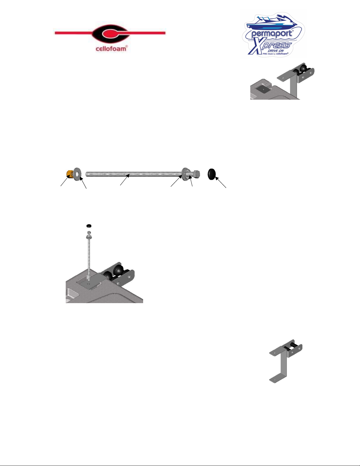
Many of the parts of the permaport are heavy; do not lift any parts that are beyond
your capability, use additional help to maneuver parts into position.
When working near the water it may be advisable to tie a line to any parts that are
liable to sink until they are attached. These should be attached to inanimate secure
objects only.
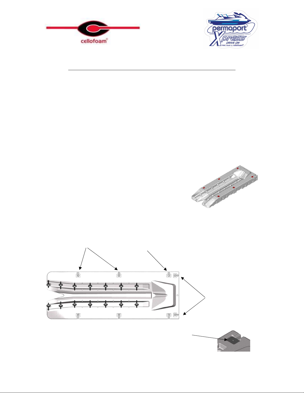
Installation to the dock requires holes to be drilled and possibly wood to be cut,
these operations should only be carried out by competent persons.
Water and electricity do not mix well, do not use corded power tools, hand tools
are preferable or battery powered. Battery powered tools up to 20v are safe but
will be damaged if submerged.
If you have any doubt about installing the Permaport consult the Dock Specialist
that supplied the unit.
Safety Instructions (Use)
The Permaport has Heavy Duty Steel attachments for long life and durability.
These components are heavy and extend below the water line below the
Permaport. It is inadvisable to swim near, under or from the Permaport due to the
possibility of entrapment or injury from protruding parts.
Entry onto the Permaport is designed to be a low speed operation; it is advisable
that the Watercraft be brought to a complete standstill in line with the Permaport
with the bow keel touching the centered between the first set of rollers. A small
amount of throttle is all that is required in order to propel the watercraft on to the
Permaport. Do not vacate the watercraft until it is fully stationary and the engine
is turned off. WARNING: Over throttling the watercraft upon entry can result in
impacting the dock or sliding too far forward on the Permaport.
Do not load or unload the watercraft with passengers other than the driver.
Ensure that there are no obstructions or persons in the water near the Permaport or
on the Permaport when loading or unloading the watercraft.

- 4 -
Stop engine as soon as the Watercraft is on the Permaport, do not allow engine to
run while out of the water. Do not start the engine while the watercraft is on the
Permaport. Refer to Watercraft owner’s manual for further details.
Mounting Hardware
Permaport Xpress is designed to be mounted at the front. Out of preference side
mounting is possible but is not optimal
The standard hardware is suitable for both side and front mounting the Permaport to both
fixed and floating docks. In the case of extremely rough water or unusual conditions there
may be additional or alternative parts required.
It is advisable that this dock be installed by a professional dock builder. Failure to mount
the dock in accordance with the manufacturer’s instructions will invalidate the warranty.
Tools required
The Permaport has been designed to be installed with the minimum amount
of assembly and requiring only basic tools.
Note: It is essential that any electrical tools used outdoors be protected by adequate GFCI
protection, we recommend that only hand or Battery operated tools be used in close proximity to
water
3/4” Wrench or Long Reach Socket and ratchet drive (Preferred)
Drill and 9/16” Drill Bit
Wrench or Socket and Ratchet Drive
For a fixed dock installation the vertical
support poles need to be driven into the
lake bed, it is recommended that at least
a manual fence post driver be utilized for
this purpose.
Maintenance
The only maintenance that is required is the periodic greasing of the Roller Axles. A
spray on dry lubricant is recommended for this purpose. (available from most Hardware

- 5 -
stores). We recommend that this be carried out once a year or if the rollers appear to be
stiff in operation.

- 6 -
Permaport Parts List
Ensure that all of the parts are available before starting assembly.
Permaport Hull Including 14 Fitted Rollers
and 6 void fillers.
One permaport Bracket with contoured rollers
One Permaport Bracket with straight rollers
Two Dock Brackets
Four Shock Absorbing Inserts
Two ½” x 14” Stainless Steel Bolts
Two ½” Brass Lock Nuts
Four ½” Stainless Steel Washers

- 7 -
Two raised Washers and Plastic caps
Two Pipe caps
lanyard
Xpress Step
Other Parts required (Not Included)
2” Diameter Schedule 40 Galvanized Pipe (Length to suit).
Due to variances in dock design and materials used, screws for attaching the dock
hardware to the dock are not supplied.

- 8 -
Attachment
points for
Front Mount
Rear Attachment
points for Side Mount
Front Attachment
point for Side Mount
Basic Assembly Applicable to all Applications
It is recommended that the basic mounting kit be applied to the Permaport away from the
water to avoid the possibility of loss of components
It is essential that all threads are coated with an anti seize compound prior to assembly,
failure to do so will complicate any future disassembly that may be required and will
invalidate the warranty.
There are large holes placed along the edges. Select the holes to be used, for front mount
use the two on the front edge, for side mount select two holes on the side edge, the front
point and one of the rear points, it is preferable to use the rear most position if possible.
The Permaport Xpress is supplied in a front mount
configuration, there are void fillers in the side holes. To
use for a side mount remove the void fillers from the holes
to be used for mounting and re-position then in the front
holes. To remove the fillers, use a screwdriver to pop off
the black caps and remove the bolt using a 9/16” socket
and a 9/16” wrench. Replace them in the front positions
using the same assembly as used in the side holes.
Place a shock absorbing insert in both the top and bottom rectangular
recesses on the selected holes
As Supplied

- 9 -
Install a Permaport Bracket by sliding over the inserts
Assemble the 14” long Stainless steel bolt as shown. Do not attach the plastic cap.
Insert a 14” long x ½” stainless steel bolt through the assembly and attach the ½” Brass
Lock nut and washer on the bottom.
Tighten the nuts using a ¾” wrench or Long Reach Socket, do not over tighten the nuts,
they need to be snug without causing undue compression of the Permaport. Finally, snap
the Plastic caps over the bolt heads onto the contoured washers.
There are two different types of rollers, on a front mount application the
position is unimportant. On a side mount application, it is important that
the straight rollers are in the rear position.
Washer
Lock Nut
Bolt
Raised Washer
Plastic cap
Washer

- 10 -
Attaching the Dock Hardware
It may be necessary to remove part of the Dock Planking in order to adequately fix the brackets on this
assembly, Lag screws should not be used, it is critical that bolts and washers are used to mount this
assembly. The permaport should not be attached to stringers that are less than 2” x 6” or in a decayed or
damaged condition. Take care not to drill through the floats under the dock
When Mounting to a fixed Dock it is essential that the water level is not able to come to within 15” of the
top of the dock. If there is a possibility this may occur the installation needs to be adapted to accommodate
this situation.
Front Mount
Determine the position that the Permaport is to be attached and mark a line on the stringer
representing the center of the Permaport. Mark a line 24” from the center line to both the
right and the left hand sides, these are the center lines of each of the Dock Brackets.
Alternatively, mark one line 5” from the edge of where the Permaport is to be positioned
and then a second line 48 “ from the first.
Position the Dock Bracket so the center of the tube lines up with the line
drawn on the dock, ensure that the bracket is firmly against the stringer
and drive in the two wood screws supplied (Note: If necessary, chamfer
the top front edge of the dock).

- 11 -
Repeat for the other dock Bracket, float the Permaport up to
the dock and ensure that the Permaport brackets line up
with the dock brackets by sliding a piece of the 2” schedule
40 pipe in the dock brackets and into the Permaport
brackets. If everything lines up insert the remainder of the
bolts in the front of the Brackets.
It is unimportant which type of roller is on which side.

- 12 -
Side Mount
Determine the position that the Permaport is to be attached and mark a line on the stringer
representing the center of the forward attachment point. This MUST be a minimum of
24” from any adjoining dock at the front.

- 13 -
There are two options for the rear attachment, the one toward the rear is the preferential
position but the position in the center of the Permaport is acceptable if the dock
configuration makes it necessary to use that position.
After deciding on the second position to be used, it is necessary to take an actual
dimension from the Permaport in order to determine the exact position for installing the
dock brackets. Measure the exact dimension between the centers of the holes, having
determined that dimension Mark a Line on the dock as shown. Do not use the
approximate dimensions.
Position the forward most dock Bracket so the center of
the tube lines up with the line drawn on the dock,
ensure that the bracket is firmly against the stringer and
drive in the two wood screws supplied (Note: If
necessary, chamfer the top front edge of the dock).

- 14 -
Repeat for the other dock Bracket, float the
Permaport up to the dock and ensure that
the Permaport brackets line up with the
dock brackets by sliding a piece of the 2”
schedule 40 pipe in the dock brackets and
into the Permaport brackets. If everything
lines up insert the remainder of the bolts in
the front of the Brackets

- 15 -
Attaching to a Fixed Dock
This System Must Not Be Used If There Is a Possibility Of The Water Level
Rising To Within 15” Of The Bottom Of The Pipe Brackets, contact your
supplier for alternative instructions
It is essential that the poles on the fixed dock are both Parallel and Upright, if the poles are not parallel
then the Permaport could bind as the water rises and falls, this could cause damage or loss to the
Permaport, the watercraft or injury to persons.
It will we necessary to use 2 lengths of 2” schedule 40 Galvanized Pipe that are at least
24” longer than the water depth when measured from the top of the Dock.
Position the Permaport under the Dock
brackets as shown and slide the two lengths
of pipe through the dock bracket and the
Permaport brackets ensuring they are
upright and parallel. Drive the pipes in to
the lake bed to anchor them. It may be
preferable but not essential to leave the
Pipes long to form a handle to assist in
accessing the permaport. Two pipe caps are
supplied in the kit if this is decided upon.
Tighten the locking
screws on the Dock
Brackets and lock
with the nuts.

- 16 -
Attaching to a Floating Dock
It will we necessary to use 2 lengths of 2” schedule 40
Galvanized Pipe. Measure the distance between the top of the
dock and the top of the permaport (Dim A). You will need 2
pieces of 2” Diameter, schedule 40 galvanized pipe that is at
least 36” longer than that dimension. If you want to leave the
pipe above the dock to act as a handle to assist in accessing the
Permaport that needs to be added to the length of the pipe.
Position the Permaport under the Dock
brackets as shown and slide the two lengths
of pipe through the dock bracket and the
Permaport brackets ensuring that they
protrude at least 20” below the Permaport
bottom face.
Tighten the bolts and locking nuts on the
brackets
Note: On some floating dock installations where the free
board is low the Permaport bracket may come close to the dock
bracket, in that instance, it is permissible to install the
permaport Brackets reversed as shown
For floating docks that are subject to rough water conditions there is additional hardware
supplied in the separate hardware box.
The directions for utilizing this additional feature are contained in the hardware box.
Should we send another Urethane clamp and a diagonal arm for rough water??

- 17 -
Adjusting the Rollers
Note: all of the component parts of the wheel axle assembly will sink in
water, use care when removing the assembly.
As supplied the rollers are positioned such that they will accommodate the majority of
PWC’s on the market. However, it may be necessary to change the position for use with
certain PWC’s where the rollers interfere with the contours of the hull.
The two entry rollers are not changeable and are tighter than the rest of the rollers, do not
remove these rollers unless it is for service replacement, in which case will need to be
replaced in the same configuration.
The rollers can be reconfigured to one of three positions on each axle and placed into any
of the positions on the Xpress port.
Removal of Wheels
To remove a wheel assembly use a lever such as a 2” x 2” piece of wood. Ensure that
there are no sharp parts that may puncture the body of the Xpress.
Insert the end under the axle as shown and gently but firmly apply upward pressure until
the whole assembly comes free from the main body.
As Supplied
Lowest Position
Highest Position

- 18 -
Re-Assembly of Wheels
Slide one end of the assembly into a recess and then using a protective piece of wood or
plastic drive the other end into the opposing recess using a hammer as shown. Do not
apply lubrication as an aid to insertion.
Other Cellofoam Docking Station manuals