Electrify America innogy eBox professional User manual

Dock installation instructions

DOCK INSTALLATION INSTRUCTIONS

CONTENTS
Contents
Important safety instructions
Qualifications for electrical work 6
EMC compliance statement 6
Electric vehicle charger characteristics 7
General and electrical specifications 7
Product overview
Included in delivery 8
Dock – product details 9
Specifications 9
Installation instructions
Before installing 10
Compatible electrical network type 11
Choosing the site 12
Routing the connecting cable 12
Line selection 12
Tools needed 13
Information on mounting 14
Mounting the Dock on a wall 14
Preparing the electrical connection 16
Ethernet link (optional) 16
Welding detection 17
Electrical connection 18
Single power supply line to the Dock 18
Almost done: electrical tests and sealing 19
Clicking the charger into the Dock
Linking the charger to the Electrify America app
Dismounting 24
Disposal 24
Legal notice 27
In case of questions or problems with this
product please contact Electrify America
Customer Assistance: 1-833-532-2778.

DOCK INSTALLATION INSTRUCTIONS
IMPORTANT SAFETY
INSTRUCTIONS
These installation instructions
are intended for specialized
electricians. Only qualified,
specialized electricians should
hardwire the Dock. In addition to
the Dock installation Instructions,
follow all federal, provincial and
local laws, regulations, ordinances,
codes and safety standards.
In addition to this manual, take
notice of the accident prevention
regulations, the safety rules applying
nationwide to the specific operations,
and the medical regulations at the
workplace.
These Dock Installation Instructions
describe how to store, install, use,
service, and, if necessary, dismount
and dispose of the charger and Dock
properly. For your personal safety,
follow these Dock Installation
Instructions exactly.
These operating instructions
constitute an integral part of the
product and must be available
to the installers even after the
installation. So keep this document
in a safe place after installation
and for the life of the product. Provide
these Dock installation Instructions
to any future owner of the charger.
Note: For your safety, these devices
must be stored, installed, used,
serviced, and, if necessary, dismounted
and disposed of properly.
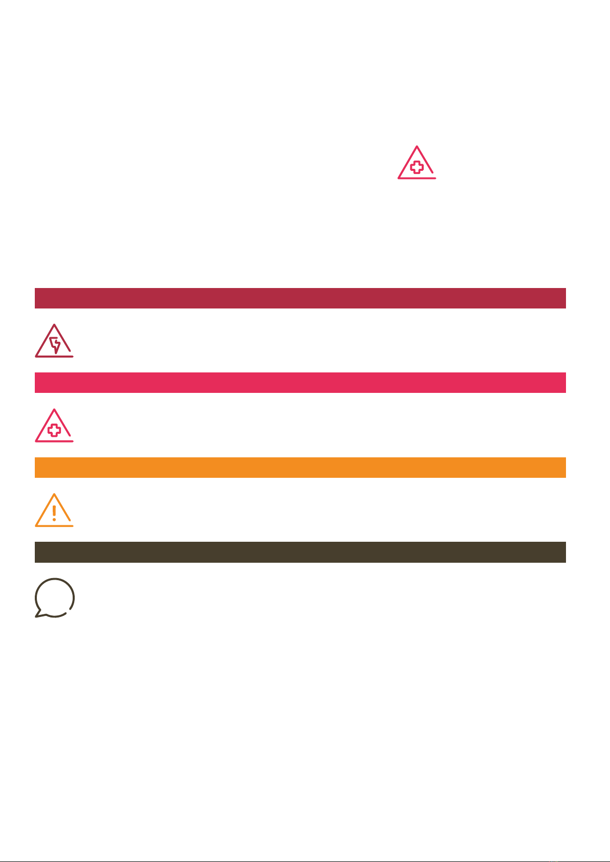
Slight injury and / or material damage
This symbol in conjuction with the key word CAUTION indicates a possibly hazardous situation.
It might cause slight or minor injuries or damage to the product or objects in its vicinity if not avoided.
CAUTION
Improvement of the application
This symbol in conjuction with the key word NOTE indicates hints for the user or very useful information.
This information helps with installation, set-up and operation of the product to promote normal operation.
NOTE
Risk of fatal injury
This symbol in conjuction with the key word DANGER indicates an imminent danger.
It will cause death or severe injuries if not avoided.
DANGER
Personal injury
This symbol in conjuction with the key word WARNING indicates a possibly hazardous situation.
It might cause death or severe injuries if not avoided.
WARNING
SAVE THESE INSTRUCTIONS.
THEY MUST BE PROVIDED TO
EACH NEW OWNER.
WARNING
When using electric products,
always follow basic precautions,
including the following:

• Read all the instructions before
installing, operating, maintaining,
or using this product.
• Supervise children when device is
in use. Children under 16 should
not operate this device.
• Do not put fingers into the electric
vehicle connector.
• Do not use this product if the power
cord or the electric vehicle cable
is frayed, has broken insulation, or
any other signs of damage.
• Do not use this product if the
enclosure or the electric vehicle
connector is broken, cracked,
open, or shows any other indication
of damage.
• The maximum ambient temperature
rating for this device is +122°F (+50°C).
• Use only copper wire rated minimum
194 °F (90 °C), maximum 7 AWG for
connecting to main power supply.
• Do not use extension cord to
increase the length of the charging
cable.
• Installation must be performed
only by a qualified, specialized
electrician. Dock must be inspected
by a qualified electrician prior to
initial use.
• Follow all federal, provincial and
local laws, regulations, ordinances,
building codes and safety standards
when installing or using this device.
• If an applicable law, regulation,
ordinance, building code or safety
standard would not permit you to
complete a step as described in
these Dock Installation Instructions,
contact Electrify America Customer
Assistance at 1-833-532-2778.
• Electrify America is not responsible
for physical injury, damage to
property or equipment caused by
the installation of this product.
• This document provides instructions
for the Dock and must not be
used for any other product. Before
installation or use of this product,
the user must read and review this
manual carefully and consult with
a licensed contractor, licensed
electrician, or trained installation
expert to make sure of compliance
with local and national building
codes and safety standards, climate
conditions, and all applicable codes
and ordinances.
• These Dock Installation Instructions
describe the most commonly used
installation and mounting scenarios.
If it is not possible to perform an
installation following the procedures
provided in this document, contact
Electrify America. Electrify America
is not responsible for any damages
that may occur from custom
installations that are not described
in these Dock Installation Instructions.
• Personal protection equipment:
Use proper personal protection
equipment, including, but not limited
to eye protection, shock protection,
gloves, and other appropriate
protection when installing or
servicing any electrical equipment.
• Arcing component in contactor:
The Dock includes contactors that,
when opened or closed, will cause
a short duration arc. The contactor
is enclosed in an appropriate
electrical enclosure, but caution is
required if this arc occurs in the
presence of flammable vapors, as
the vapors could ignite, creating an
explosion. Store hazardous
and flammable vapors and
materials away from all electrical
equipment. If hazardous or
flammable sources are present,
allow sufficient time for
ventilation before operating
the Dock.
Do not open the charger at any
time during installation or
operation! Only trained personnel
should open the Dock.
Product subject to modification
without prior notice. This
document might not contain
the latest changes to the
product's specifications or
processes described herein.
Visit www.electrifyamerica.com/
charging-at-home for the most
up to date information.
CAUTION
To reduce the risk of fire,
connect only to a circuit provided
with 1 x 40 A maximum branch
circuit overcurrent protection
in accordance with the National
Electrical Code and local
standards regulations and codes.
CAUTION
Ensure that all components are
dry throughout the installation.
IMPORTANT SAFETY INSTRUCTIONS
DANGER
Handling live electrical
components.incorrectly
may cause grievous injuries
or death.
DANGER
Choking hazard. Small parts are
dangerous for children. Do not
install in the presence of children.
WARNING
If the electricity service to the
Dock or charger is damaged,
immediately shut down the
power to the Dock / charger
by switching off the circuit
breaker and contact a licensed
electrician.
WARNING
The product must not be
installed in ex-zones (potentially
explosive atmospheres)

DOCK INSTALLATION INSTRUCTIONS
Qualifications for electrical work
The qualified electrician performing the electrical installation, maintenance,
and/or dismounting of the device must have read and must follow these Dock
Installation Instructions.
EMC compliance statement
Note: This equipment has been
tested and found to comply with
the limits for a Class B digital device,
pursuant to Part 15 of the FCC Rules.
These limits are designed to provide
reasonable protection against
harmful interference in a residential
installation. This equipment
generates, uses, and can radiate
radio frequency energy and, if not
installed and used in accordance
with the instructions, may cause
harmful interference to radio
communications. However, there is
no guarantee that interference will
not occur in a particular installation.
If this equipment does cause
harmful interference to radio or
television reception, which can
be determined by turning the
equipment off and on, the user is
encouraged to try to correct the
interference by one or more of
the following measures:
• Reorient or relocate the receiving
antenna.
• Increase the separation between
the equipment and the receiver.
• Connect the equipment into
an outlet on a circuit different
from that to which the receiver is
connected.
• Consult the dealer or an experienced
radio/TV technician for help.
This device complies with part 15 of
the FCC rules. Operation is subject
to the following two conditions:
1. This device may not cause harmful
interference, and
2. This device must accept any
interference received, including
interference that may cause
undesired operation.
innogy eBox professional with Wi-Fi
innogy SE
Model: innogy eBox professional
Contains FCC ID: QIPEHS8
FCC ID: 2AKBXIEKA 160

IMPORTANT SAFETY INSTRUCTIONS
Electric vehicle charger characteristics
1. The product must be connected
to AC supply power.
2. The product can be installed and
used in indoor and outdoor areas.
3. The product can be installed
on walls.
4. The Dock and charger together
are rated electrical protection
class IP I. The open dock
(i.e., without the charger) is rated
electrical protection class IP I.
Do not provide external GFCI on the supply power circuit as it may conflict with the internal GFCI of the charger.
General and electrical
specifications Dock
Charging power up to 7.6 kW (up to 32 A)
Mains input power Dock:
240 Volt AC split phase, 40 A, 7.6 kW
Output power to charger
Dock:
240 Volt AC split phase, 32 A, 7.6 kW
maximum output depends on local distribution grid
Operating temperature -22 °F to 122 °F (-30 °C to +50 °C) full load
Electrical Protection Class I
Max. line cross-section
Max. supply line
(top or bottom):
7 AWG (10 mm²)
Certifications UL and FCC certificate (tested and confirmed by a certified body)

DOCK INSTALLATION INSTRUCTIONS
Product overview
Together, the Dock and charger unit form the home charging solution
for electric vehicles. Thanks to its modular design, the Dock can also
be installed without the charger, which is then fitted at a later time.
The Dock can be mounted on a suitable wall.
Included in delivery
1 Dock with 3 sealing plugs
1 installation instructions in English
3 round head screws
1/4" x 2 1/3" (6 x 59 mm)
3 universal dowels
1 M32 cable gland
(fitted in routing plate)
1 M20 cable gland
1 M20 x 1.5 lock nut
1 cable clip (galvanized steel)
1 drilling template
Wall
Dock
charger
WARNING
Check the contents of the delivery
for completeness and intactness.

Specifications
Measurements H x W x D 1'-4" (399 mm) x 6" (155 mm) x 2 ½" (62 mm)
Installation type Wall
Weight Approx. 1 kg (2.2 lb)
Enclosure rating Type 3S (with charger)
Operating temperature -22 °F to 122 °F (-30 °C to +50 °C) full load
Voltage supply 240 Volt AC split phase, 32 A at 7.6kW
Power supply Max. 40 A (configurable)
Connected load Up to 7.6 kW; maximum load
PRODUCT OVERVIEW
4
7
1
Dock – product details
2
3
3
6
6
6
5
1 Dock
2 Contact guard
3 Cable routing plates
4 Locking bracket
5Mains board
6Sealing plug
7 Interface board

DOCK INSTALLATION INSTRUCTIONS
Before installing
Check and ensure that the electrical installation intended
for connection can supply the required electrical power.
Each Dock must be protected with its own circuit
breaker in the pre-installation. No additional electrical
devices may be integrated in any of these circuits.
Circuit breaker required for installation, and must conform to all
national and local laws, regulations, ordinances, codes and safety
standards. Licensed electrician performing installation should
choose correct circuit breaker depending on grid type and power.
Installation summary
1. Checks: Make sure that the circuit breaker has been
installed in the sub-panel on the power supply circuit to
this device.
2. Power supply line: The cable routing plates may have
to be switched over, depending on whether the supply
line is routed from the top or bottom.
3. Ethernet cable: Before connecting an Ethernet cable
(optional), first drill a hole for an M20 thread according
to the enclosed cable gland through the corresponding
routing plate.
4. Make sure that the contact guard is snapped into
place. Use the provided seal to secure the contact
guard on the Dock so that is is not possible to remove
the contact guard without breaking the seal.
IMPORTANT SAFETY INSTRUCTIONS. SAVE THESE INSTRUCTIONS.
THEY SHOULD BE PROVIDED TO EACH NEW OWNER.
INSTALLATION INSTRUCTIONS
DANGER
Danger of electrical shock
or injury. Before installing,
familiarize yourself with the
safety instructions. Follow
all federal, provincial and
local laws, regulations,
ordinances, codes and
safety standards.

INSTALLATION INSTRUCTIONS
CAUTION
For space reasons, the supply
line chosen must have,
whenever possible, a cable
size no greater than 10 AWG
(6 mm²).
CAUTION
When multiple charging points
are to be installed, every tenth
must be provided with additional
earthing.
Compatible electrical network type
Connection: L1, L2, PE
Maximum charging capacity:
240 V, max. 40 A, max. 7.6kW
Dock
CB
Split phase
L1
PE
L2

Choosing the site
Consult the customer concerning the choice of a suitable
site. The optimal site for the charging station depends
on the owner’s needs and the parking and wiring
environment.
For masonry walls such as cinder block walls, for
example, use ¼" (6.35 mm) screw anchors. Ensure that
the screws used fit properly into the screw anchors and
are at least 2½" (63.5 mm) in length.
For wooden walls, use at least ¼" (6.35 mm) screws.
Ensure that the screws have a length of at least 2 ½"
(63.5 mm) and that the screws penetrate the wood at
least 2" (50.8 mm).
For hollow walls, connect at least two studs using a
channel stud for each height – top and bottom – of the
holes of the Dock, connect the studs using the associated
brackets. Ensure that the correct channel strut nuts are
used and use 5/16" (7.93 mm) screws with a length of at
least 2" (50.8 mm) so that the screws fully enter the
channel strut nuts.
When fastening the Dock with the screws, please
make sure that the screws are fastened tightly into the
bolt anchor / wall.
To ensure adequate heat dissipation and proper
functioning of the device, place the dock at a generous
distance from surrounding objects. We recommend
20", depending on ambient temperature.
DOCK INSTALLATION INSTRUCTIONS
DANGER
Do not install or use this
product in an area with
hazardous or flammable
materials or vapors.
Line selection
When selecting the cable for connection to a compatible
electrical AC power circuit, follow all national and local
laws, regulations, ordinances, codes and safety standards.
Routing the connecting cable
Route the cable of adequate conductor area to the
site chosen. Note that only cables not exceeding 7 AWG
(10 mm) in size may be introduced into the Dock
(maximum bending radii). The routed cables may
therefore have to be rewired before they are inserted
into the Dock.
Once the required cables have been routed,
the pre-installation is complete.
CB

Tools needed
To mount the Dock on a wall, you will need a spirit level,
the drilling template provided in the packaging, a pencil
or other marker, an 0.315" (8 mm) drill bit, a screwdriver,
an electric drill with step bit, and a cordless screwdriver
with torque display. You will also need a side cutter,
a pair of round nose pliers, and, for cable assembly,
a cable knife and a MultiStrip.
INSTALLATION INSTRUCTIONS
Drilling template
Side cutter
Round nose pliers
Cable knife
MultiStrip
Stepped drill bit for M20 thread
(optional for installing an Ethernet
cable and/or for wiring a welding
indicator relay)
Hammer drill
Level
Screwdriver (Phillips, slotted head 5/32" (4 mm))
Pencil
Allen key 1/8" (3 mm)
Drill bit 5/16" (8 mm)

Mounting the Dock on a wall
After choosing a suitable site and making all of the
preparations, you can now mount the Dock.
01
The Dock packaging contains a
drilling template that simplifies the
mounting work. Use this if necessary.
Use the template and a level to
mark the three holes on the wall, or
drill directly through the positioned
template.
For full accessibility to the charger,
the upper hole should be 3'-9" (1.15m)
above the floor.
Standard height:
5' (1.5 m)
For full accessibility
of charging only:
3'-9" (1.15 m)
DOCK INSTALLATION INSTRUCTIONS
Information on mounting
The Dock is secured through three screw holes to the
wall. To start, place the rear side of the Dock on a flat
surface, and remove the contact guard. The contact
guard is clipped without screws to the Dock. It is replaced
after the connection to the main power supply.
Use a screwdriver to remove the contact guard. To do
this, insert the screwdriver into the slots on the side of
the contact guard and carefully lift it.
WARNING
The Dock must be mounted on a flat
surface so that the Dock does not deform.

03
Screw the Dock to the wall using the
screws provided.
04
Insert the provided sealing
plugs.
02
Drill the holes with an 5/16" (8 mm)
bit, and insert the provided wall
plugs. If the provided screws are
unsuitable for the wall type at
the chosen location, use another
type of suitable fastener.
INSTALLATION INSTRUCTIONS
CAUTION
You must insert the provided
sealing plugs, otherwise water or
other substances may penetrate
and damage the product.

Preparing the electrical
connection
Make sure that the hole in the cable routing plate is
facing the side where you want to insert the supply
cable. If not, pull out and change over the plates.
DOCK INSTALLATION INSTRUCTIONS
Ethernet link (Use this option only if a WiFi
internet connection cannot be established)
An Ethernet cable can be used to integrate the charger
in the customer’s network. It is important to know the
connections on the interface board for the Ethernet
connection.
1LAN 1 RJ45 (charger communication over LAN)
2a LAN 2 RJ45 (deactivated)
2b LAN 2 LSA plus (deactivated)
3a Clip for S/FTP cable
3b Clip for S/FTP cable
4Expansion terminal
(charger communication for eSmartMeter)
5GPIO
6Welding detection
7LAN LSA-Plus to internet router
CAUTION
When inserting the cable
routing plates, make sure
that they are flush.
2a
90°
1
7
2b
3a
3b 4
6
6
Ethernet cable
8
7
6
5
4
3
2
1

INSTALLATION INSTRUCTIONS
Welding detection
The signal for welded power contacts is connected
to position 6 of the interface board (see fig. p. 16).
A change-over contact (max. 230 V, 1 A) is available,
which can be used according to the installer’s
requirements.
12 V / 24 V variant
Interface board
Fuse box
Circuit
breaker
L1
12 V / 24 V DC
2 A max
e.g. ABB F2C-A1
Mechanical
coupling
GND
L2 L3 N
L1 L2 L3 N
40 A
To Dock mains board
Welding
indicator
COM
NC NO
01
Drill a suitable hole for the M20 cable gland using the
step drill. Drill step by step to ensure that the hole is not
too large and that there is no leakage after the cable
gland has been installed. Insert the M20 cable gland.
02
Replace the routing plate in the Dock, and press this on
firmly to ensure tightness.
03
Insert the S/FTP cable (Ethernet cable) through the
M20 cable gland and the cable ducts and secure
the cable under clip 4a or 4b. Route the cable to the
clip, strip the insulation, and use an SLA-Plus tool to
place it on the LAN 2 LSA-Plus terminal strip (7) of
the interface board.
04
Tighten the cable gland to ensure tightness.
M20 cable gland
Cable routing plate
8
RX-
RX-
RX+
RX+
TX-
TX-
LAN 1LAN 2
set free
TX+
TX+
Not used.
6
3
2
1

DOCK INSTALLATION INSTRUCTIONS
Single power supply line to the Dock
(if NEMA power plug is not used for supply power)
Introduce the supply cable into the Dock from the
top (T) or the bottom (B). Now place the wires on
the contacts as depicted in the figure, and close the
terminals to fix the contacts.
Installation is made much easier by using the
pre-wired NEMA 14-50 power plug and inserting it
into a standard NEMA 14-50 outlet that is installed
on a dedicated branch circuit with a 40 A circuit
breaker in the feed panel. If you choose to
hard-wire the unit to supply power follow the
instructions below.
T
Electrical connection
CAUTION
The complete product –
consisting of Dock and charger –
has no facilities for the
attachment of additional
ventilation components.
WARNING
The conductor size may not
exceed 7 AWG (10 mm²)
(bending radii of the cables).
DANGER
HAZARD OF ELECTRIC SHOCK,
EXPLOSION, OR ARC FLASH.
ENSURE THAT POWER IS OFF!
B

INSTALLATION INSTRUCTIONS
Almost done: electrical tests and sealing
Once all cables have been configured and secured as
depicted in the respective figure, tighten the screws
(if necessary). You may now switch in the voltage and
conduct the electrical tests.
DANGER
There is a risk of electric shock
and danger to life and limb.
CAUTION
1. After the electrical tests, switch OFF the circiut breaker.
2. Put the contact guard back onto the Dock.
3. Use the provided seal to secure the contact guard on the Dock so that it is
not possible to remove the contact guard without breaking the seal.
WARNING
If the charger is to be installed
at a later time, disconnect the
Dock from the main power supply
by unplugging the dock and/or
switching off the circuit breaker
and cover the Dock to prevent
electric shock or accidents and
to keep the Dock dry and free
from dust and particles.

DOCK INSTALLATION INSTRUCTIONS
Clicking the charger
into the Dock
90°
3a
3b
1
6
2b 4
5
01
Take the charger and
identify the connecting
points (Shown here
circled in blue) on its
rear side.
02
Connect the black ribbon
data cable of the charger
to the port “5 Expansion
Terminal” at the bottom
right of the Dock.
03
Place the white ribbon
data cable of the charger
on port 1 on the left of
the Dock.
After the electrical installation, the charger
can be clicked into the Dock. Before
mounting the charger, make sure
there is no voltage across the Dock by
unplugging the power cable or by
disconnecting the main power supply
at the circuit breaker.
2a
1 LAN 1 RJ45 (charger communication)
2a LAN 2 RJ45 (deactivated)
2b LAN 2 LSA-Plus (deactivated)
3a eSmartMeter output (optional)
3b eSmartMeter input (optional)
4 Cable clips for S/FTP cable
5 Expansion terminal
(charger communication)
6 LAN 1 LSA-Plus to internet router
Table of contents