Celsus MRA-470D User manual

www.celsusice.co.uk
www.celsusice.co.uk
MRA-470D
IPX7 4 Channel Marine-Grade Micro Digital Amplifier
The MRA-470D is a state-of-the-art amplifier designed to deliver
great performance from a small 203 x 89mm/ 8” x 3.5” footprint.
This 4 channel full-range class D amplifier benefits from an IPX7
waterproof rating ensuring that it is suited to the harsh marine
environment, optimised for a boat, jet-ski or off-vehicle application.
MRA-470D boasts fully variable high pass and low pass crossovers
enabling it to drive loudspeakers in a variety of configurations. A
versatile and powerful amplifier to sit at the heart of your high-end
audio system.
In the box
MRA-470D Amplifier
Waterproof DIN > RCA adaptor cable
Power cable & 40A fuse
Mounting Screws
Read this document in full before proceeding with installation.
Installation should only be performed by an experienced and
qualified technician.
Owner’s Manual & Set-up Guidance
Specification
Power output at 4Ω - 70W x 4
Power output at 2Ω - 90W x 4
Power output at 4Ω Bridged - 200W x 2
Size L x W x H: 20.3 x 8.9 x 3.8cm (8 x 3.5 x 1.5”)
Colour
Function
Connection
Red
+ 12v
Input
Black
Ground
Input
Blue
Remote: Do Not Connect
Speaker Outputs
Green/Black
Rear Left -
Output
Green
Rear Left +
Output
Purple
Rear Right +
Output
Purple/Black
Rear Right -
Output
White/Black
Front Left -
Output
White
Front Left +
Output
Grey
Front Right +
Output
Grey/ Black
Front Right -
Output
RCA Adaptor
Phono Cable
Signal
Input
Yellow
+12v (Max Current draw 300mA)
Output
Blue
Remote
Input
Black
Ground
Output
*** Wiring configuration diagram overleaf ***

www.celsusice.co.uk
www.celsusice.co.uk

www.celsusice.co.uk
www.celsusice.co.uk
Important Safety Information
A.) Water damage caused by improper installation procedure is not
covered by warranty.
Our engineering team designed this amplifier chassis to be IPX7
waterproof rated however it must be installed where its protected
from water/mud at all times.
The sealed structure is designed and constructed to protect the
amplifier in case it accidentally gets wet. It is the responsibility of the
owner/ installer to limit the amplifier’s exposure to wet areas,
especially immersion.
Install the amplifier in a dry area where water cannot reach it
Do not clean the amplifier with a high pressure hose.
B.) Do not use the Blue remote-in wire (labelled ‘do not connect’ in
the diagram on the previous page) within the input harness when
using a Celsus Bluetooth controller as your audio source. The
amplifier utilises a remote trigger within the RCA adaptor provided.
If you are in any doubt please contact our technical support
technical@celsusgroup.net
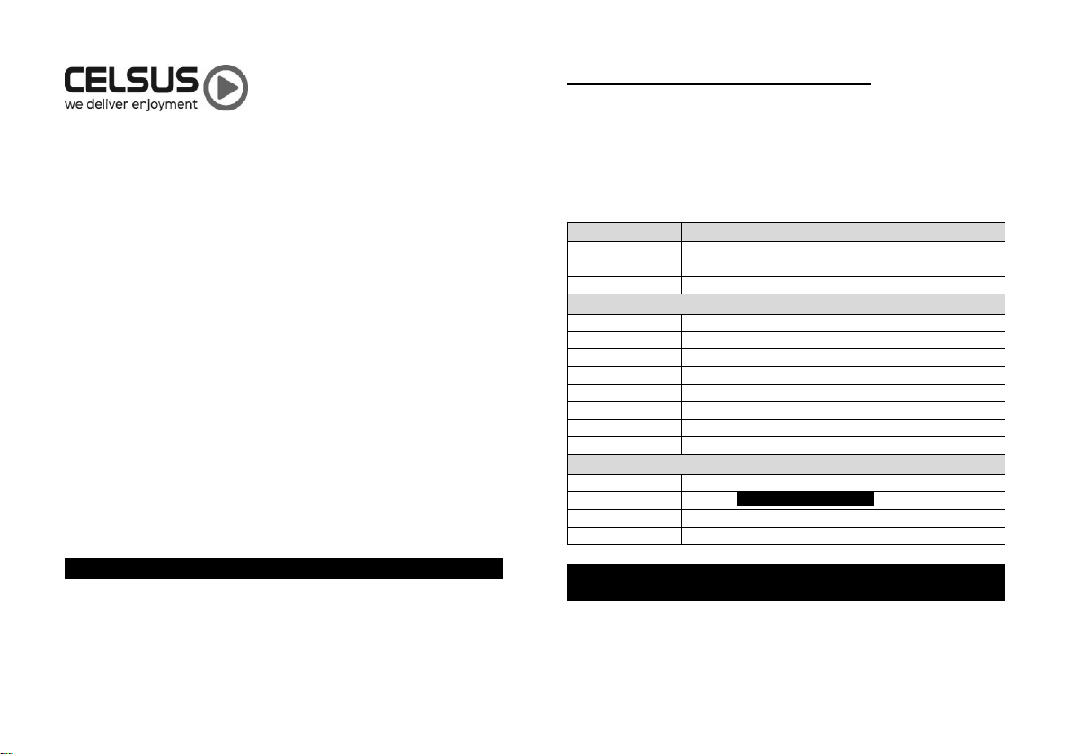
C.) Installation Application
MRA-470D is designed for operation with 12 volts, negative ground
electrical systems. Using this product in systems with positive
ground and/or voltages other than 12v may result in damage to the
product and void all warranty.
D.) Safety Considerations
Having an amplifier sealed to the elements at IPX7 rating means that
the heat generated from the amplifiers normal function has nowhere
to escape. When played for extended periods the amplifier chassis
may get hot, this is perfectly fine and expected but avoid touching
the amplifier surface during or right after use.
Do not mount the amplifiers in the engine compartment or any other
areas of extreme heat. Mounting the amplifier in the engine
compartment will void all warranty.
Securely mount the amplifier so that is will not come loose in the
event of a collision/ sudden jolt or as a result of repeated vibration
during normal operation of your vessel or vehicle.
Check before drilling to make sure that you will not be drilling into an
exterior panel/ hull, fuel tank, fuel/ brake line, wiring harness or any
other vital system.
Do not run system wiring outside or underneath the vessel/ vehicle.
This extremely dangerous practice can result in severe damage or
injury. Your system should be installed by a professional technician.
Protect all system wires from sharp edges (metal, fibreglass etc.) by
carefully routing them, tying them down and using grommets where
applicable. Secure all wiring as needed using cable ties or wire
clamps to protect them from moving parts.

www.celsusice.co.uk
www.celsusice.co.uk
E.) Battery and charging
When setting up and tuning the system it will be drawing current
from the battery. Monitor the battery voltage from time to time and
recharge if it gets low.
Aftermarket audio equipment such as this amplifier will put an
increased load on the vehicle’s battery and charging system. We
recommend checking your alternator and battery condition to ensure
the electrical system has enough capacity to handle the increased
load of your stereo system.
Stock electrical systems which are in good condition should be able
to handle the extra load of the MRA-470D amplifier without
problems, although battery and alternator life can be reduced
slightly. To maximise the performance of your amplifiers we suggest
the use of a heavy-duty battery.
F.) Installation Procedure / Connections
The installation of this product should be undertaken by an
experienced technician.
Before installation disconnect the negative battery post
connection and secure the disconnected cable to prevent
accidental reconnection during installation. This is an essential
safety precaution during installation.
Avoid running power wires near the low-level input cables,
antenna, power leads, sensitive equipment or harnesses. The
power wires carry substantial current and could induce noise
into audio system.
1. Connect RED power lead to the positive (+12V) battery post.
2. We strongly recommend to run the Black/Ground cable to the
negative (-12V) battery post.
a. Blue/Remote turn-on (in the power harness) should
not be used. The RCA Adaptor contains a remote
trigger wire for turn-on.
3. Fuse. The amplifier already includes a 40A fuse. The MRA-
470D power wires are 2.4M (8ft) long, while the fuse housing
located on the Red positive power cable is located at 1.5M (5ft)
of wire from the amplifier.
a. It is recommended that the fuse holder is located
within 40cm of the battery positive terminal
4. Run the speaker wires to the amplifiers output. Make sure
correct polarity when connecting your speakers to the amplifier.
Speaker connection colour codes.
Speaker Outputs
Green/Black
Rear Left -
Output
Green
Rear Left +
Output
Purple
Rear Right +
Output
Purple/Black
Rear Right -
Output
White/Black
Front Left -
Output
White
Front Left +
Output
Grey
Front Right +
Output
Grey/ Black
Front Right -
Output
5. Secure the amplifier
6. Connect the RCA adaptor harness to the Amplifier and connect
directly to the Celsus BTC10-001 Controller as follows;
RCA Adaptor BTC10-001
Yellow Red
Black Black
Blue Blue
RCA RCA

www.celsusice.co.uk
www.celsusice.co.uk
(Point 6 continued…) The RCA adaptor harness Power,
Ground & Remote connections can only be used with the
Celsus BTC10-001 and must not be used with any other
product.
The Amplifier can be damaged by connecting the RCA Adaptor
harness Power, Ground & Remote to any other product (other
than BTC10-001) and will not covered by warranty.
If the Amplifier is to be connected to another product (not the
BTC10-001) then the Power, Ground & Remote must not be
connected to the RCA Adaptor harness and an alternative
power source located (i.e. the battery) and the Remote input
connected to the Blue wire that is part of the “main amp supply
harness”.
7. Power up system & check the control panel setting. (section G)
For troubleshooting see end of manual.
G.) Control Panel Settings & Adjustments
The amplifier’s settings and controls are located on the side panel
beneath a gasketed, protective cover. Remove the five Allen head
screws from the centre panel to access the controls and make
adjustments. Replace cover when finished and secure amplifier.
Amplifier set-up and gain adjustment is critical to a great sounding
audio system and should be undertaken by an experienced
specialist. This will avoid distortion and potential damage to your
speakers.
Power/ Protect Indicator
This indicator will light up RED upon initial amplifier start up. If all
connections are ok, within 3-5 seconds the light will turn BLUE. If a
condition of protect (short circuit, over/ under voltage) occurs the
light will turn RED until the condition of protect is resolved.
Control Panel settings
The control panel settings required on the amplifier depending on
the system design (speaker / subwoofer configuration.
This amplifier can be used in three modes
4 stereo loudspeakers
2 stereo loudspeakers (Bridged front & rear channels)
2 stereo loudspeakers and 1 subwoofer (Bridged Mono
rear output)
Always check compatibility of the equipment being used. Your
speakers / subwoofer must be able to handle the continuous power
of the amplifier.

www.celsusice.co.uk
www.celsusice.co.uk
In all modes and configurations the input gain (SENS) should be
tested and tuned in accordance with the speakers and audio source
used. This requires a multi-meter. GAIN IS NOT VOLUME
CONTROL.
Gain (SENS) is used to match the input of the amplifier to the source
unit. The higher the sensitivity the sooner the amplifier will reach
maximum output.
‘FREQ’ (Crossover control) The variable crossover on the
amplifier allows the adjustment of cross over frequency
‘HPF’(High Pass Filter) configures filter to attenuate
frequencies below the selected filter frequency
‘LPF’(Low Pass Filter) configures the filter to attenuate
frequencies above the selected filter frequency
‘FULL’ Full Range operation of all frequencies.
H.) Troubleshooting
Problem
Cause
Solution
Does not sound
right
Speaker are not connected
correctly
Refer to experienced
installer
Control panel settings are wrong
Amplifier does
not turn on
Controller/ Head unit was not on
Turn on source
Faulty Fuse
Remove fuse and check
continuity. Replace fuse if
necessary
Poor connection integrity
Check ‘+12V’ and ‘Ground’
cables for pinched wires.
Ensure tight connections.
Balance
reversed
Speaker L & R reversed
Correct speaker wire
orientation
Output distorted
Volume set too high at source
Lower volume
Amplifier gain set too high
Lower gain (SENS)
Whining or
ticking noise
while the engine
is ON
Amplifier is picking up alternator or
radiated noise
Move audio cable away
from power cables
Turn down input gain
(SENS)
Check the alternator and/or
voltage regulator. Test for
weak battery.
Specifications
Output power at 4 OHM
70W x 4
Output power at 2 OHM
120W x 4
Output power at 4 OHM Bridged
200W x 2
Waterproof level
IPX7
Total Harmonic Distortion
<1%
S/N Ratio Ref 1W @ 4 OHM
>90dB
Gain Range
0.2V –5V
Crossover Range
40Hz –500Hz
Frequency Range
20Hz –20KHz
Table of contents