Century 974W25 User manual

INSTALLATION, OPERATION, MAINTENANCE & PARTS
NOTE: MANUAL including SPECIFICATIONS, subject to change without notice
All ratings specified are based on structural factors only,
not vehicle capacities or capabilities.
NOTES
OWNER’S MANUAL
Century Wrecker
Item No. 974W25
(Century Model 925)
LEGENDARY
FORM NO. 7205001
7 / 95
PRICE $15.00
CENTURY®
A Division of Miller Industries Towing Equipment Inc.
P.O. Box 120 •8503 Hilltop Drive
Ooltewah, Tennessee 37363
Phone (423)238-4171 •FAX (423)238-5371
CENTURY®

CENTURY®warrants to the original purchaser that each new CENTURY wrecker or other CENTURY
products will be free from defects in material and workmanship for a period of twelve (12) months from
date placed in service, but in no event shall such warranty period exceed twenty-four (24) months from
date of manufacture by CENTURY. The purchaser must promptly notify CENTURY in writing of any
failure in material or workmanship. In no event shall CENTURY accept such notification later than
twenty-four (24) months from date of delivery or twelve (12) months from date placed in service,
whichever is earlier.
CENTURY’s obligation under this warranty, statutory or otherwise, is limited to the repair or
replacement at the CENTURY factory, or at a point designated by CENTURY, of such part or parts as
shall appear upon inspection by CENTURY to be defective in material or workmanship. New or
remanufactured parts will be used for any replacement at CENTURY’s option.
This warranty is not transferable.This warranty does not obligate CENTURY to bear the cost of labor or
transportation charges in connection with the repair or replacement of any parts found to be defective,
nor shall it apply to a product upon which repairs or alterations have been made unless authorized by
CENTURY.
EXCEPT AS EXPRESSLY SET FORTH IN THIS WARRANTY, CENTURY MAKES NO OTHER
WARRANTY, EXPRESS OR IMPLIED, AND HEREBY DISCLAIMS ALL OTHER WARRANTIES
INCLUDING, BUT NOT LIMITED TO, THE IMPLIED WARRANTIES OF MERCHANTABILITY AND
FITNESS FOR A PARTICULAR PURPOSE. CENTURY shall in no event be liable for claimed
downtime, claimed loss of profits or goodwill, or any other special, incidental, indirect, or consequential
damages concerning or relating to any product or parts, whether based on negligence, strict liability,
breach of contract, breach of warranty, misrepresentation or any other legal theory, regardless of
whether the loss resulted from any general or particular requirement which CENTURY knew or had
reason to know about at the time of sale.
CENTURY MAKES NO WARRANTY, EXPRESS OR IMPLIED, AS TO THE FINISHED PRODUCTS
MANUFACTURED OR SUPPLIED BY ANOTHER MANUFACTURER AND SUPPLIED BY CENTURY
TO PURCHASER, including, but not limited to, any vehicle to which a CENTURY product may be
affixed or any accessories or wire rope, and CENTURY EXPRESSLY DISCLAIMS ANY IMPLIED
WARRANTIES OF MERCHANTABILITY OR FITNESS FOR A PARTICULAR PURPOSE AS TO
SUCH EQUIPMENT OR PRODUCTS. This language shall in no way affect or diminish the rights of the
purchaser to rely on such warranties as are extended by such manufacturers or suppliers. CENTURY
shall, to the extent permitted under applicable law, pass on to the purchaser such manufacturer’s or
seller’s warranty.
CENTURY, whose policy is one of continuous improvement, reserves the right to improve its products
through changes in design or materials as it may deem desirable without being obligated to incorporate
such changes in products previously sold. This warranty is not intended to cover or include the
following items, which are set forth by way of example and not limitation:
A. Normal deterioration of trim, paint, lettering, and appearance items due to wear or exposure to
weather, road conditions, road treatments, etc.
B. Any damage or defect due to accident, misuse, abuse, improper or unauthorized repairs, failure
to provide reasonable and necessary maintenance, or uses for which the equipment was not
designed or intended.
C. Alterations or modifications that affect performance, operation or reliability.
D. Normal maintenance parts including, but not limited to, wear pads, bushings, wire rope, mud flaps,
fenderettes, light bulbs, hydraulic oil, filters, and tow sling belts.
IT IS EXPRESSLY UNDERSTOOD THAT CENTURY MAKES NO IMPLIED WARRANTY THAT
CENTURY PRODUCTS SHALL BE FIT FOR THE PURPOSE OF LIFTING OR MOVING PEOPLE
OR FOR ANY OTHER IMPROPER USE.
LIMITED WARRANTY
CENTURY®
A Division of Miller Industries Towing Equipment Inc.
8503 Hilltop Drive •P.O. Box 120
Ooltewah, Tennessee 37363
Telephone (423) 238-4171
SERIAL NUMBER
REVISED 12/1/93
CENTURY®
A Division of Miller Industries Towing Equipment Inc.
8503 Hilltop Drive •
••
•Ooltewah, Tennessee 37363 •
••
•(423) 238-4171
Mailing Address: P.O. Box 120 •
••
•Ooltewah, Tennessee 37363 •
••
•Telex: 856967 CENWKRTN UD

OWNER, USER AND OPERATORS:
CENTURY®appreciates your choice of our wrecker for your
application. Our number one priority is user safety which is best
achieved by our joint efforts. We feel that you can make a major
contribution to safety if you, as the equipment owner and operator:
1. Comply with Federal, State, and Local Regulations.
2. Read, Understand, and Follow the Instructions in this Manual.
3. Use Good, Safe Work Practices in a Common Sense Way.
4. Only have Authorized and Trained Operators running the
Wrecker.
Also contained in this manual is a Parts Section for your Wrecker.
Use of other than Factory or Factory Authorized Parts will render
the Warranty void.
i
© 1995 MILLER INDUSTRIES TOWING EQUIPMENT INC. All rights reserved.
Reproduction or use, without express permission, of editorial or pictorial content, in any
manner, is prohibited.
Section IVA - OPERATING INSTRUCTIONS
WHEEL LIFT (cont’d)
4A.9 HOOK-UP FOR VEHICLE WITH FLAT TIRE(S) (cont’d)
(i) Raise the vehicle and place blocks on timbers beneath the
flat tire. Lower the Wheel Lift allowing the tire to rest on
the blocking.
(j) Engage parking brake and place transmission in gear (park)
of the disabled vehicle.
(k) Extend Wheel Lift further, allowing the crossbar to compress
the tire further. Re-adjust Tire Restraint as far as possible
into the flat tire. This ensures the rim of the wheel will rest on
the crossbar and tire restraint.
(l) Raise Wheel Lift and remove blocking from beneath the
tire.
(m) Install Safety Strap on flat tire. Refer to Section 4A.7,
SECURING VEHICLE TO BE TOWED.
(n) When tightening Safety Strap around a flat tire be certain it
has the tire completely collapsed. This ensures proper
installation of the strap on a flat tire. See Figure 4A.15.
IVA-11
FIGURE 4A.15

TABLE OF CONTENTS
The operator must read and understand
all instructions in this manual
before operating the wrecker.
ii
It is assumed by CENTURY that the Owner/Operator has thorough
knowledge of the accepted and lawful retrieval and towing methods as
dictated by his city, county, or state. CENTURY rejects any liability claim
that may result from the incorrect or unlawful application of its equipment.
Section I - SAFETY PRECAUTIONS I-1 thru I-15
Section II - SPECIFICATIONS II-1 thru II-5
Section III - OPERATIONAL FUNCTIONS
WRECKER III-1 thru III-5
FORMULA III IIIA-1 thru IIIA-3
Section IV - OPERATING INSTRUCTIONS
WRECKER IV-1 thru IV-8
FORMULA III WITH TILT IVA-1 thru IVA-18
STEERING WHEEL LOCK IVB-1 & IVB-2
Section V - MAINTENANCE V-1 thru V-7
MAINTENANCE RECORD V-6 & V-7
Section VI - PARTS VI-1 thru VI-38
BODY ASSEMBLY VI-2 & VI-3
FORMULA III ASSEMBLY VI-4 & VI-5
FORMULA III HYDRAULICS
STANDARD VI-6 & VI-7
WITH OPTIONAL HAND HELD REMOTE VI-8 & VI-9
OUTER CROSSBAR & LIFT ADAPTERS VI-10 & VI-11
925 WRECKER ASSEMBLY VI-12 & VI-13
Section IVA - OPERATING INSTRUCTIONS
WHEEL LIFT (cont’d)
IVA-12
4A.10 OUTER CROSS TUBE REMOVAL
(a) Loosen "T" Handles and fully extend Outer Cross Tubes.
(b) Insert a screwdriver or 1/4" rod into Stop Rod Hole located
beside "T" Handle. See Figure 4A.16.
FIGURE 4A.16
(c) While pushing in to release Stop Rod, pull outer crosstube
off the crossbar. To reinstall outer crosstubes, simply
slide them onto the crossbar. The Stop Rod will
automatically engage when slid all the way on. Tighten "T"
Handles.
4A.11 TOW FORK ADAPTERS
(a) Remove outer crosstubes.
(b) Loosen "T" Handles on Fork Adapters and slide onto
crossbar. See Figure 4A.17.

TABLE OF CONTENTS (cont’d)
iii
Section VI - PARTS (cont’d)
925 WRECKER BOOM HYDRAULICS VI-14 & VI-15
WINCH MOTOR HYDRAULICS VI-16
HYDRAULIC CYLINDERS
WRECKER VI-17
FORMULA III VI-18 & VI-19
PUMP & FILTER HYDRAULICS VI-20 & VI-21
CONTROLS & CROSSRODS VI-22 & VI-23
HYDRAULIC WINCH ASSEMBLY VI-24 & VI-25
BOOM END SWIVEL ASSEMBLY VI-26
REAR JACK HYDRAULICS VI-27
LIGHTBAR ASSEMBLY VI-28
HEAVY DUTY TRUCK HITCH VI-29
LIGHT KIT VI-30 thru VI-32
GLAD HAND ASSEMBLY VI-33
AIR OPERATED FREE SPOOL CLUTCH VI-34 & VI-35
KING PIN ASSEMBLY VI-36
CONVENIENCE GROUP VI-37
VERNIER THROTTLE VI-38
Section VII - SCHEMATICS
ELECTRICAL VII-1 thru VII-10
HYDRAULIC VII-11 & VII-12
Section IVA - OPERATING INSTRUCTIONS
WHEEL LIFT (cont’d)
IVA-13
4A.11 TOW FORK ADAPTERS (cont’d)
FIGURE 4A.17
NOTE
THE FORK ADAPTERS CAN BE PLACED IN ANY OF FOUR
(4) POSITIONS AND ANY LOCATION ON THE CROSSBAR.
SEE FIGURE 4A.18.
FIGURE 4A.18

NOTES Section IVA - OPERATING INSTRUCTIONS
WHEEL LIFT (cont’d)
IVA-14
4A.12 TOW FORK & ADAPTER APPLICATIONS
(a) Align Wheel Lift with disabled vehicle.
NOTE
STEPS (b) THROUGH (d) ARE NOT NECESSARY
PERMITTING THE AXLE IS HIGH ENOUGH TO ALLOW
EXTENSION OF BOOM WITH FORKS AND ADAPTERS
INSTALLED ON CROSSBAR.
(b) Extend the Boom (without adapters or forks) until crossbar
is centered with axle of disabled vehicle.
(c) Raise vehicle until tire can be blocked up high enough to allow
forks to clear axle when installed onto the crossbar.
(d) Block up tires and lower Boom until boom can be retracted
for installation of adapters and forks.
(e) Install adapters in desired configuration on crossbar. Select
and install desired forks into adapters. Refer to Figure 4A.19.
(f) Extend Boom until Forks are beneath axle or frame as desired.
(g) Manually adjust adapters on crossbar to a point where the
forks will come in contact with the frame or axle in the desired
towing position.
(h) Tighten "T" Handles on adapters. Attach safety chains
around axle or frame, crossbar and forks as shown in
Figure 4A.19.

I-1
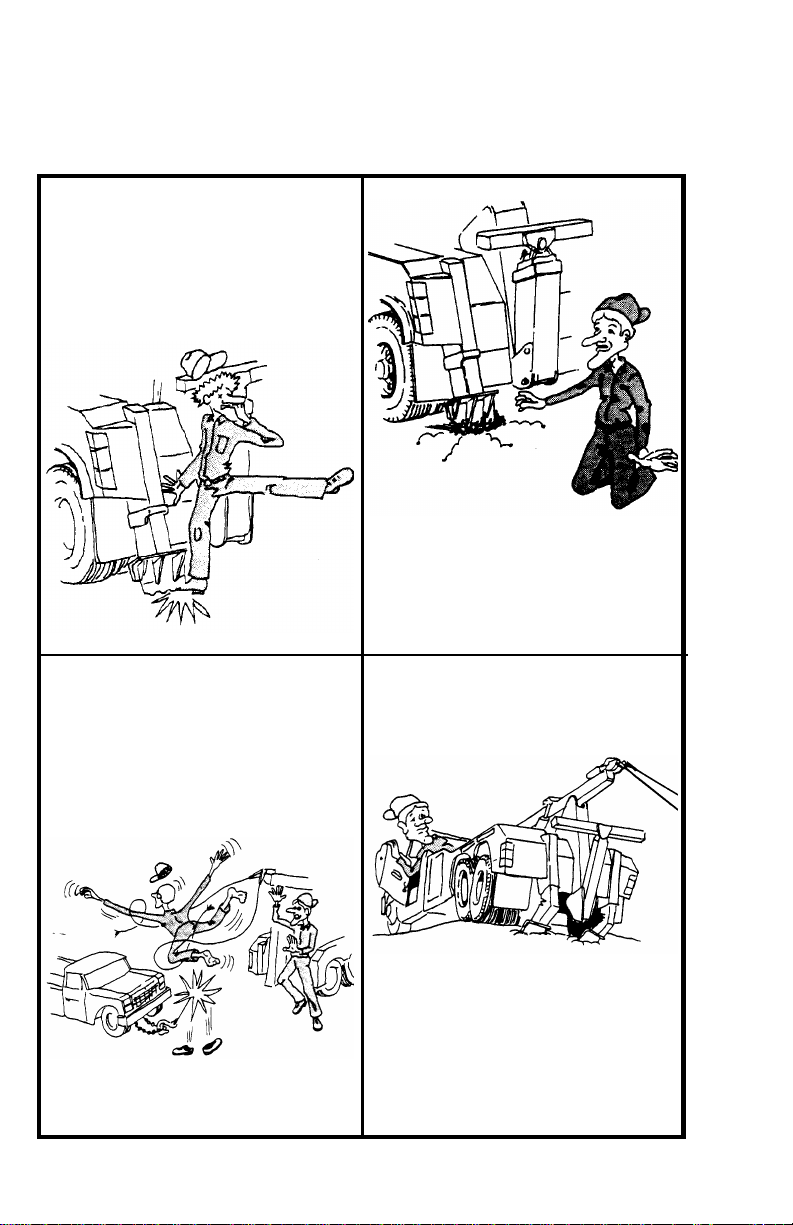
Section I - SAFETY PRECAUTIONS
Presented in the interest of safety for all wrecker operators.
NOTICE
You are obligated to operate your
wrecker safely. You can be held legally
responsible for injuries or damages
resulting from unsafe operating
practices.
The manufacturer’s recommendations
for operating this wrecker can help you
avoid unsafe practices and their bad
consequences. These
recommendations are contained in this
manual.
Century is not responsible for
the results of any unsafe practice of
wrecker operators. Furthermore, the
division is not responsible for the failure
of the wrecker or its accessories
resulting from improper maintenance.
The danger from an automobile does not cease when it is
disabled or wrecked. Recovering and towing automobiles can
be dangerous, too! The danger threatens wrecker operators
and everyone close at hand. As a wrecker operator you must
develop an awareness of the hazards involved. You must use
every safeguard within reason to prevent injuries.
For each step in operating your wrecker develop the habit of
asking yourself if it is safe to proceed. Carefully check all
rigging (especially snatch blocks) before starting a heavy lift
or pull.
We cannot warn you of all the possible dangers you will
encounter. But we will tell you of the most common hazards
we know about. Learn them well.
Section IVA - OPERATING INSTRUCTIONS
IVA-15
4A.12 TOW FORK & ADAPTER APPLICATIONS (cont’d)
FIGURE 4A.19
(i) Raise vehicle to desired height for towing.
(j) Remove any blocks previously placed under the tires.
(k) Retract Boom pulling disabled vehicle as close to the
Wheel Lift body as possible while maintaining enough
distance for sharp turns.
(l) Raise Boom to desired towing height.
(m) Pull excess Safety Chain back into Storage Caddy. Be
certain to allow enough slack for sharp turns.
USE SAFETY CHAINS
ON ALL TOWING AND
LIFTING APPLICATIONS
WHEEL LIFT (cont’d)

I-2
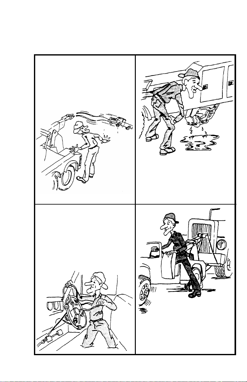
Section I - SAFETY PRECAUTIONS (cont’d)
1.1 Improper use of this equipment can be dangerous! Incorrect operation
can result in bodily injury to the operator and bystanders. Therefore,
a thorough understanding of the "operating principles" and "operating
instructions" as found in this manual is essential.
1.2 Study each job to be done. Apply common sense judgment to
assure safety to yourself and bystanders.
1.3 Plan ahead. Work safely. Avoid accidental damage and injury. If an
accident or fire does occur, react quickly with the tools and skills at
hand. Know how to use a first aid kit and a fire extinguisher - and
where to get assistance.
1.4 Read and understand the following instructions.
1. READ THE MOUNTING/OPERATING/MAINTENANCE MANUAL
FOR WARNINGS AND PRECAUTIONS.
2. NEVER TAKE ANYTHING FOR GRANTED. DON’T ASSUME THAT
EVERYTHING IS ALL RIGHT AT THE START OF WORK TODAY
JUST BECAUSE EVERYTHING SEEMED ALL RIGHT AT THE END
OF WORK YESTERDAY. BEFORE BEGINNING OPERATION,
THOROUGHLY INSPECT THE ENTIRE WRECKER TO BE SURE IT
IS IN GOOD OPERATING CONDITION.
3. VISUALLY INSPECT THE WRECKER FOR EVIDENCE OF
PHYSICAL DAMAGE, SUCH AS CRACKING, BENDING, OR
DEFORMATION OF PLATES OR WELDS. INSPECT CAREFULLY
FOR CRACKING OR FLAKING OF PAINT, WHICH MAY INDICATE
A DANGEROUS CRACK IN THE STRUCTURE BENEATH. DO NOT
OPERATE UNTIL REPAIRS ARE MADE.
4. LOOSE OR MISSING HARDWARE, BOLTS, NUTS, AND PINS
SHOULD BE PROPERLY TIGHTENED OR REPLACED WITH
MANUFACTURER’S SPECIFIED HARDWARE.
5. CHECK FOR FLUID LEAKS. HYDRAULIC SYSTEM MUST BE
CORRECTED BEFORE THE WRECKER IS OPERATED.
Section IVA - OPERATING INSTRUCTIONS
WHEEL LIFT (cont’d)
IVA-16
FIGURE 4A.20
SAFETY CHAIN MUST BE SEATED IN BOTTOM OF SLOT
BEFORE ATTEMPTING TO TOW VEHICLE.
SEE FIGURE 4A.20
4A.12 TOW FORK & ADAPTER APPLICATIONS (cont’d)
4A.13 SPRING LIFT BRACKETS
(a) Align Wheel Lift with disabled vehicle.
(b) Position fork adapters in desired configuration on crossbar,
secure them in place with retaining pins and install spring lift
brackets into fork adapters. See Figure 4A.21.

I-3
Section I - SAFETY PRECAUTIONS (cont’d)
INSPECT ALL HYDRAULIC HOSES, ESPECIALLY THOSE WHICH
FLEX OR MOVE IN SERVICE, AND REPLACE IF NECESSARY.
SECURE ALL CAPS AND FILLER PLUGS FOR ALL SYSTEMS.
6. YOUR CLOTHING SHOULD BE RELATIVELY CLOSEFITTING.
7. ALWAYS WEAR PROTECTIVE ITEMS SUCH AS SAFETY
GLASSES, GLOVES, REFLECTIVE CLOTHING AND SAFETY
SHOES.
8. BEFORE OPERATING THE BOOM, REFER TO THE BOOM
CAPACITY LABELS ON THE BOOM AND INSIDE THE DOOR OF
THE CAB AND IN THE SPECIFICATIONS SECTION OF YOUR
OPERATING MANUAL. FOR CHASSIS CAPACITY, CONSULT
YOUR TRUCK DEALER. NEVER EXCEED MANUFACTURER’S
LOAD RATING. THE STIPULATIONS PERTINENT TO THESE
RATINGS SHALL ALWAYS BE CAREFULLY OBSERVED. RATINGS
SHOWN ARE BASED ON THE HYDRAULIC, MECHANICAL, OR
STRUCTURAL DESIGN OF THE WRECKER RATHER THAN
STABILITY. IT IS ALWAYS UNSAFE TO APPLY ANY LOAD WHICH
IS GREATER THAN RATED LOAD SHOWN ON THE DATA PLATE.
9. DO NOT USE THIS EQUIPMENT EXCEPT ON SOLID, LEVEL
SURFACE WITH STABILIZERS PROPERLY EXTENDED AND
TRUCK BRAKES LOCKED.
10. OPERATE ALL CONTROLS SLOWLY AND SMOOTHLY TO
AVOID DAMAGE TO WRECKER OR INJURY TO PERSONNEL.
11. DO NOT OPERATE, WALK OR STAND BENEATH BOOM OR A
SUSPENDED LOAD.
12. NEVER LIFT LOAD OVER ANYONE.
13. DO NOT USE BOOM TO LIFT PEOPLE.
14. KEEP LOAD WITHIN ONE FOOT OF THE GROUND WHENEVER
POSSIBLE.
15. FOR TRAVEL, BOOM MUST BE IN STOWED POSITION AND
P.T.O. DISENGAGED.
IVA-17
FIGURE 4A.18
(c) Extend boom until spring brackets are under front spring
hangers of vehicle to be towed. It may be necessary to tilt
the boom down in order for the spring brackets to clear the
vehicle bumper.
(d) Manually adjust spring lift bracket on crossbar to a point
where the forks will engage the springs at the front hanger
brackets. See Figure 4A.22.
FIGURE 4A.21
4A.13 SPRING LIFT BRACKETS (cont’d)
WHEEL LIFT (cont’d)
Section IVA - OPERATING INSTRUCTIONS
I-4
Section I - SAFETY PRECAUTIONS (cont’d)
ONLY AUTHORIZED AND TRAINED PERSONNEL
SHOULD BE PERMITTED TO OPERATE THIS WRECKER
UNSUPERVISED
TRAINED PERSONNEL ARE THOSE WHO HAVE WORKED
UNDER EXPERIENCED SUPERVISION AND HAVE PERFORMED
ALL WRECKER MANEUVERS, HAVE READ THE MOUNTING,
OPERATING AND MAINTENANCE MANUAL, WARNINGS AND
PRECAUTIONS, AND UNDERSTAND AND HAVE HAD
EXPLAINED TO THEM BY THEIR EMPLOYER THE HAZARDS OF
OPERATING THE WRECKER. THEY MUST BE FAMILIAR WITH
THE HAZARDS OF OPERATING AT A SITE WHERE ELECTRIC
POWER LINES, IRREGULAR GROUND CONTOUR, WATER, ICE,
MUD, OR OTHER CONDITIONS CAN INTERFERE WITH
ORDINARY CAREFUL OPERATION OF THIS WRECKER.
AN UNTRAINED OPERATOR SUBJECTS HIMSELF AND
OTHERS TO DEATH OR SERIOUS INJURY.
STAND CLEAR
WHILE OPERATING
OUTRIGGERS
USE SAFETY CHAINS
ON ALL TOWING AND
LIFTING APPLICATIONS
Section IVA - OPERATING INSTRUCTIONS
WHEEL LIFT (cont’d)
4A.13 SPRING LIFT BRACKETS (cont’d)
(e) Raise the boom until the spring lift brackets are properly
seated under the springs at the front spring brackets. See
Figure 4A.22.
(f) Insert the spring lift bracket retaining pin through the lowest
unobstructed hole of the spring lift bracket and secure with
the safety pin.
(g) Attach safety chains around the springs, brackets and
crossbar in such a manner as to prevent any movement to
front or rear.
(h) Raise the vehicle to the desired height for towing and retract
boom pulling vehicle as close as possible while maintaining
enough distance for sharp turns.
IVA-18
I-5
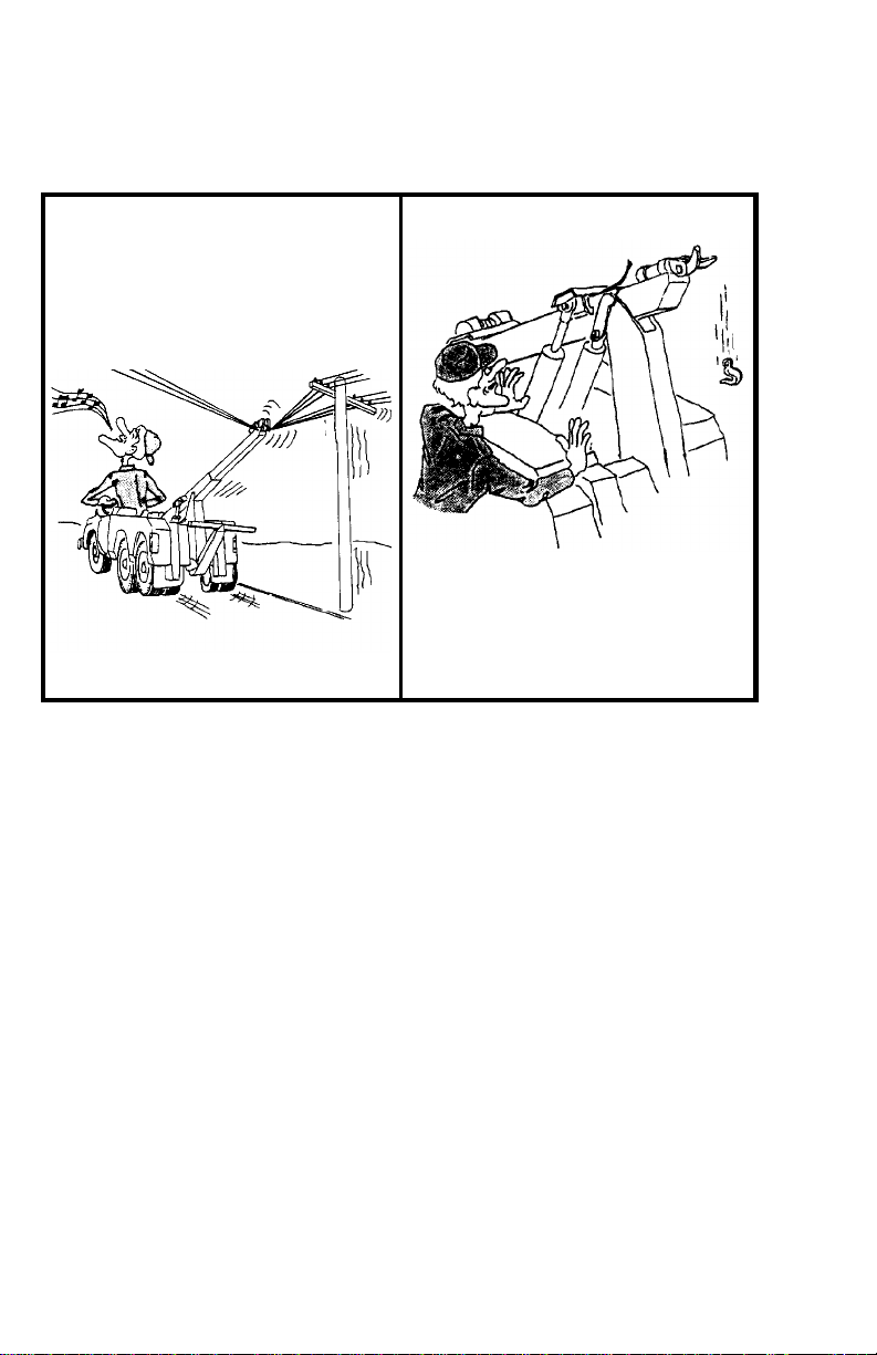
Section I - SAFETY PRECAUTIONS (cont’d)
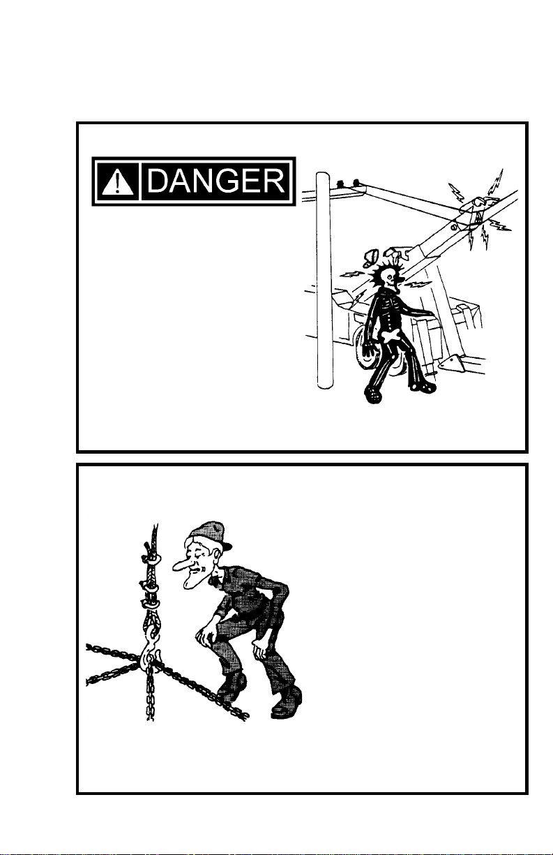
SAFETY TIPS
Death or serious injury can
occur when working near
power lines.
Learn - beforehand - as
much about your working
area as possible. Be sure
that exact locations of
overhead power lines, and
other obstructions or
hazards are known.
Don’t use winch cables with
hooks attached by means of
cable clips. Use only cables with
hooks attached by means of
thimbles and machine swaged
terminals.
USE CABLE CLIPS ONLY IN
THE EVENT OF AN
EMERGENCY FIELD
TEMPORARY REPAIR.
Use at least three clips spaced
3-4 inches apart and reduce the
cable working limit by 20%.
U-bolt of the clip should never be
around the live or long end of the
cable. Replace clips as soon as
possible with swaged cable
termination.
IVB-1
FIGURE 4B.1
2. Turn steering wheel so that front wheels are directed straight
ahead.
3. Insert latch of steering wheel lock into its buckle. Make sure
it locks in place. See Figure 4B.1.
4. Place steering wheel grip on bottom of steering wheel and
secure it by tightening jam nut against sliding clamp.
5. Hook seat grip under the front edge of auto seat or to a rigid
seat frame member that is securely fastened in place. Make
sure you do not hook it to a removable seat cushion.
6. Grasp the free end of the belt and pull until belt is tight.
7. Recheck jam nut to make sure it is still tight.
CARS WITH ANTI-THEFT STEERING LOCKS
SHOULD NEVER BE TOWED ON THEIR FRONT WHEELS
WHILE LOCKED IN THE TURNED POSITION
4B.1 INSTRUCTIONS FOR INSTALLATION
1. Unlock anti-theft steering lock if vehicle is equipped with one.
STEERING WHEEL LOCK
Section IVB - OPERATING INSTRUCTIONS
I-6
Section I - SAFETY PRECAUTIONS (cont’d)
SAFETY TIPS
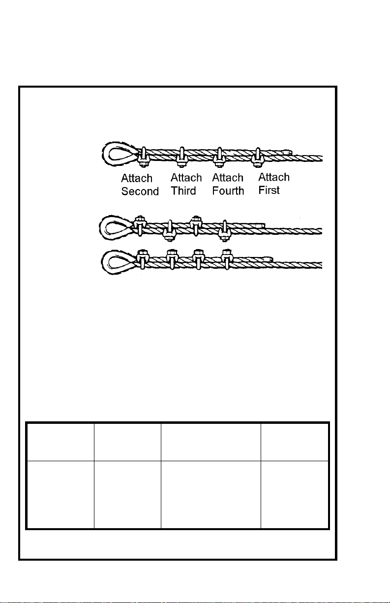
Proper technique for using wire rope clips.
USE CABLE CLIPS ONLY IN THE EVENT OF AN EMERGENCY
FIELD TEMPORARY REPAIR.
RIGHT
WAY
WRONG
WAY
1. Turn back rope length specified in the chart. Apply first clip so
U-bolt is no less than the saddle width from the dead end. Tighten
nuts evenly and torque as specified.
2. Apply next clip as near loop as thimble will permit. Turn nuts on
firm, but do not tighten.
3. Space additional clips as indicated so distance between clips is
equal. Tighten all nuts evenly and torque as specified.
4. Apply the initial load and retighten all nuts to recommended torque
Inspect periodically and retighten as needed to the recommended
torque.
CLIP SIZE
INCHES MINIMUM
NO. OF CLIPS AMOUNT OF ROPE
TO TURN BACK
IN INCHES
TORQUE
IN FT.LBS.
3/8
7/16
1/2
9/16
5/8
3/4
2
2
3
3
3
4
6 1/2
7
11 1/2
12
12
18
45
65
65
95
95
130
This table is based on Crosby-Laughlin.
IVB-2
4B.2 INSTRUCTIONS FOR REMOVAL
1. Press button on buckle of steering wheel lock, releasing the
latch.
2. Loosen jam nut and remove grip from steering wheel.
3. Unhook seat grip from seat or seat frame.
FAILURE TO PROPERLY SECURE AND TIGHTEN
THE STEERING WHEEL LOCK
COULD RENDER IT INEFFECTIVE DURING TRAVEL,
RESULTING IN A DANGEROUS TOWING CONDITION
4B.1 INSTRUCTIONS FOR INSTALLATION (cont’d)
Section IVB - OPERATING INSTRUCTIONS
STEERING WHEEL LOCK
I-7
Section I - SAFETY PRECAUTIONS (cont’d)
SAFETY TIPS
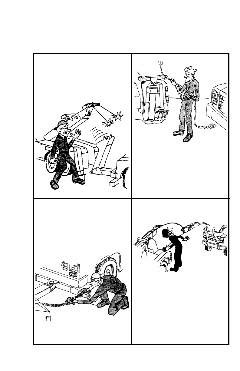
Don’t use a wrecker that has not
been properly maintained. Pay
special attention to wrecker
mounting bolts, cable condition,
and lubrication of moving parts.
Don’t use damaged cables on
your wrecker. Become familiar
with the various types of cable
damage and carefully inspect all
cables being used in a recovery
operation before starting to pull.
Always use two safety chains
when towing all vehicles,
regardless of distance.
After rigging cables, don’t begin
pulling without rechecking
connections. Make sure that all
cables and snatch blocks are
securely attached and cannot
accidentally pull loose.
5.1 The continued operation of your CENTURY Hydraulic Wrecker
is largely dependent upon strict adherence to a properly scheduled
preventive maintenance program. To help you in this program,
CENTURY has provided the following information regarding
lubrication, preventive maintenance and hydraulic system care.
5.2 HYDRAULIC SYSTEM
The importance of absolute cleanliness of the hydraulic system
cannot be over-stressed. The smallest amount of grit, metal flake or
other foreign material in the system can cause extensive damage to
pumps, motors and valves. CENTURY has taken every measure to
assure that each component and fitting was thoroughly cleaned
before your unit was shipped to you. Therefore, servicing of the
system should be done with extreme care.
(a) Before checking oil level in reservoir, wipe away all dirt, grease
and grime around filler cap before removing it. Make certain that
all containers, funnels and pouring spouts are absolutely clean
before filling reservoir.
(b) When replacing hoses, fittings or other components, clean
thoroughly; then assemble carefully.
(c) Failure to observe these precautions, and failure to change the
filter element at regular intervals could result in loss of your
warranty in the event of failure of certain components.
5.3 LUBRICATION & PREVENTIVE MAINTENANCE
The following general lubrication and preventive maintenance
should be performed at least once per month for moderate usage
or more often as required, for heavy usage.
(a) Inspect, repair or replace any worn, cracked, leaking, otherwise
damaged components including, but not limited to, the following:
1. Hydraulic Oil Filter
2. Oil Reservoir
3. Controls
4. Cables and Fittings
5. Hydraulic Hoses and Fittings
6. Lights and Wiring
7. Winches
8. Cylinders
9. Pivot Bearing Surfaces and Pins
(See Lubrication Charts, page V-4 & V-5.)
V-1
Section V - MAINTENANCE

I-8
Section I - SAFETY PRECAUTIONS (cont’d)
SAFETY TIPS
Don’t expect your wrecker to tow
loads equal to the wrecker rating.
Wrecker ratings apply to loads
imposed during recovery with the
wrecker properly stabilized.
Don’t pull a load with your winch
without making absolutely sure
that the winch drum clutch is
FULLY engaged.
Don’t attempt to recover heavy
loads without first estimating the
amount of pull that will be
required. Rig to keep the
estimated amount of pull well
within equipment ratings.
Don’t exceed ratings of booms,
cables, snatch blocks, or winches.
Stay within nameplate ratings.
Note that boom ratings decrease
significantly as boom is extended.
Section V - MAINTENANCE (cont’d)
5.3 LUBRICATION & PREVENTIVE MAINTENANCE (cont’d)
(b) Check hydraulic oil level in reservoir and fill to proper level.
Refer to 5.4, SUMMARY OF REQUIRED LUBRICANTS for
recommended oils to use.
(c) Replace hydraulic oil filters after first week of operation, then
every three (3) months thereafter.
(d) Inspect all bolts for tightness and re-tighten as necessary.
Vibration and stress may loosen even properly torqued bolts.
(e) Lubricate all grease fittings on the Wrecker and Wheel Lift weekly
including:
1. Bellcranks and Control Handle Shafts
2. Winch
3. Cables
3.Cylinder Pivot Bearings
4.Cross Bar Pivot
5. Boom and Wheel Lift Slide Pads
6.Boom End Swivels
(f) All bearing surfaces not equipped with grease fittings should
be oiled using SAE 30 oil in a pump can.
(g) Check oil level of winches and fill to proper level, level plug
on end plates, with SAE 140 general purpose gear oil.
(h) Lubricate grease fitting on winch freespool clutch control.
(i) Lubricate winch cables using an oily rag while respooling onto
drum. Other special cable lubricants are available which have
better penetrating qualities. Consult your local oil company for
a list of these.
V-2

I-9
Section I - SAFETY PRECAUTIONS (cont’d)
SAFETY TIPS
Don’t get under a raised vehicle or
load unless it has adequate safety
blocks in place.
Don’t exceed WORKING LIMIT
ratings of cable. Use breaking
strength ratings only for selecting
replacement cable.
Don’t tie down the front end of
your wrecker for recovery work or
heavy lifts. You are apt to damage
the truck frame if you do.
Don’t disengage the winch drum
clutch while the winch cable is
loaded.
Section V - MAINTENANCE (cont’d)
V-3
5.5 CARE OF HYDRAULICS IN COLD CLIMATES
Regions subject to continuous sub-zero or arctic climates require
special hydraulic fluids. Contact CENTURY or your local supplier for
information regarding specific temperature requirements.
NOTE
THERE IS NO PRACTICAL WAY TO DETERMINE
THE LIFE EXPECTANCY OF HYDRAULIC HOSES
AND OTHER RUBBER COMPONENTS.
WHILE APPEARING TO BE IN EXCELLENT CONDITION, THESE
COMPONENTS MAY BE ADVERSELY AFFECTED BY
USAGE, WEATHER OR THE PASSING OF TIME.
THEREFORE, IT IS RECOMMENDED THAT ALL
RUBBER COMPONENTS, ESPECIALLY HOSES, BE REPLACED
EVERY FIVE (5) YEARS REGARDLESS OF APPEARANCE.
5.4 SUMMARY OF REQUIRED LUBRICANTS
(a) Hydraulic Oil
Examples:
1. Texaco Rando HD 46
2. Shell Tellus Oil 46
3. Mobil Nuto H46
or EQUAL
(b) Winch Worm Gear Oil - SAE 140 general purpose gear oil.
Examples:
1. Humble - Pen-O-Led EP #5
2. Phillips - Phillips Worm Gear Oil 140
3. Shell - Macona #978
4. Sinclair - Pennant EP #6
5. Standard - Stanogear #5
6. Texaco - Maropa #5
(c) Grease - Synthetic Fortified such as Drydene SFG.
(d) Oil for miscellaneous bearing surfaces - SAE 30.
(e) Cable Oil - SAE 30 or special cable lubricant.
I-10
Section I - SAFETY PRECAUTIONS (cont’d)
SAFETY TIPS
Don’t lower out board legs or rear
jack spades unless the area under
them is clear. Pay particular
attention to keeping this area clear.
Don’t use rear spades on paved
surfaces unless you are willing to
accept responsibility for possible
damage to such surfaces.
Don’t permit bystanders in the
area while performing recovery
work.
Don’t move your wrecker while
either outboard legs or rear
spades are extended.
Section V - MAINTENANCE (cont’d)
V-4
NOTE
THE ABOVE SERVICE REQUIREMENTS
SHOULD BE SERVICED MONTHLY.
SERVICE MORE OFTEN IF THE EQUIPMENT
IS USED FREQUENTLY.
5.6 LUBRICATION - WRECKER
1. Control Handle Shafts - synthetic fortified grease
2. Cable - oily rag or approved cable lubricant
3. Winches - SAE 140 gear oil to proper level
4. Cylinder Pivot Bearings - synthetic fortified grease
5. Winch Freespool - synthetic fortified grease
6. Hydraulic Reservoir - approved hydraulic fluid to proper level
7. Hydraulic Filters - replace after first week then every three
(3) months
8. Boom End Swivels - synthetic fortified grease
9. Sheaves - synthetic fortified grease
10. Extended/Lift Cylinders - synthetic fortified grease
11. Boom Slide Pads - synthetic fortified grease
12. Door Hinges - synthetic fortified grease
LUBRICATION CHART (Wrecker)
I-11
Section I - SAFETY PRECAUTIONS (cont’d)
SAFETY TIPS
Don’t completely unwind all cable
from a winch while loaded. Keep
AT LEAST five wraps on the drum.
Don’t operate your wreckers
engine faster than recommended.
Excessive speeds can damage
PTO shafts, hydraulic pumps, and
winches.
Don’t rely on anti-theft steering
locks to secure the steering
wheel. Use a special steering
wheel clamping device. Rope is
commonly used to secure steering
wheels, but that is not as reliable
as devices designed for this
purpose.
Don’t tow a vehicle that reduces
the weight on the front wheels of
your wrecker more than 40
percent.
Section V - MAINTENANCE (cont’d)
V-5
NOTE
THE ABOVE SERVICE REQUIREMENTS
SHOULD BE SERVICED MONTHLY.
SERVICE MORE OFTEN IF THE EQUIPMENT
IS USED FREQUENTLY.
5.7 LUBRICATION - WHEEL LIFT
1. Lift Cylinder Pivot Bearings - synthetic fortified grease
2. Upper Arm Assembly - synthetic fortified grease
3. Tilt Cylinder - synthetic fortified grease
4. Wheel Lift Outer Boom - synthetic fortified grease
5. Wheel Lift Inner Boom - synthetic fortified grease
6. Wheel Lift Pivot Pin - synthetic fortified grease
7. Tire Restraint Plunger - synthetic fortified grease
LUBRICATION CHART (Wheel Lift)

I-12
Section I - SAFETY PRECAUTIONS (cont’d)
SAFETY TIPS
Don’t use towing forks that are not
of proper size for pick-up
requirements.
After you have hooked up a
vehicle for towing, don’t start the
tow until you have double checked
the hook-up, installed safety
chains, and released the parking
brakes of the towed vehicle.
Don’t travel with the wrecker PTO
engaged. Engage it only while
operating the wrecker controls.
Don’t tow a vehicle on its drive
wheels unless steps have been
taken to protect its transmission
and differential. Follow
recommendations of the vehicle
manufacturer. As an alternative,
use a towing dolly.
Section V - MAINTENANCE (cont’d)
MAINTENANCE RECORD
DATE MECHANIC WEEKLY * MONTHLY QUARTERLY SERVICE PERFORMED
* IMPORTANT: HYDRAULIC HOSES AND CABLES SHOULD BE INSPECTED
WEEKLY FOR SIGNS OF ABRASION.
V-6

I-13
Section I - SAFETY PRECAUTIONS (cont’d)
SAFETY TIPS
Don’t tow a vehicle on its front
wheels if they are damaged.
Don’t tow a vehicle on its front
wheels unless the steering wheel
is secured with the front wheels
straight ahead.
Don’t tow a vehicle at night
without proper signal lights on the
towed vehicle and the wrecker.
Don’t drive wrecker with boom
elevated.
Section V - MAINTENANCE (cont’d)
MAINTENANCE RECORD
DATE MECHANIC WEEKLY * MONTHLY QUARTERLY SERVICE PERFORMED
* IMPORTANT: HYDRAULIC HOSES AND CABLES SHOULD BE INSPECTED
WEEKLY FOR SIGNS OF ABRASION.
V-7
I-14
Section I - SAFETY PRECAUTIONS (cont’d)
SAFETY TIPS
SAFE TOWING
Don’t move wrecker or extend
boom where overhead power lines
may be encountered.
Don’t continue to wind in winch
cable after the hook is against the
boom end.
There are two key factors in safe towing:
1. Have enough front axle weight for safe steering.
2. Avoid excess rear axle weight.
The issue here is safety. Unsafe steering may cause a serious accident.
It is recommended that a safe steering formula that maintains at least 40
percent of the UNLADEN (unloaded) front axle weight, for towing, be
used.
That formula is expressed as follows: ML =.6 FAW x WB/OH
where:
ML = maximum lifted load for safe steering.
FAW = unladen (unloaded) weight at front axle.
WB = wheel base or distance between the center of the
front axle to the center of the rear axle(s).
OH = overhang or distance from the center of the rear
axle(s) to the lift point of the towing device.
NOTES
This manual suits for next models
1
Table of contents


