CE+T America Stabiliti 30C3 750/480 User manual
www.cet-america.com
Stabiliti
TM
–Islanding Switchgear Guide
The contents in document are subject to change without notice.
The products presented are protected by several international patents and trademarks.
All rights reserved.
Leading Conversion and Storage Technology for Energy Saving and Power Resilience

Disclaimer
This document is provided “as is” and CE+T America makes no representations warranties, expressed or
implied, with respect to the information contained herein. CE+T America has made reasonable efforts to
ensure the accuracy of information herein and at the time of publication. However, information is
constantly evolving and CE+T America does not purport the information provided is correct,
comprehensive, or exhaustive. This document is for informational purposes only. You should not act upon
information without consulting CE+T America or its authorized distributors.
© Copyright 2020, CE+T America. All rights reserved. No parts of this document may be reproduced in any
form without the express written permission of CE+T America. CE+T America logo are trademarks of CE+T
America. All other trademarks and service marks belong to their respective owners.

Contents
1. About This Document...........................................................................................................................5
2. Glossary of Terms.................................................................................................................................6
3. Important Safety Instructions..............................................................................................................7
4. Overview...............................................................................................................................................9
5. System Rating.......................................................................................................................................9
6. Reference Document............................................................................................................................9
6.1. MAN - 00115 –Stabiliti Series 30 KW –Installation and Operation Manual –V1.0.....................9
6.2. MAN - 00114 –Stabiliti Series 30 KW –Quick Start Guide –V1.0................................................9
6.3. Stabiliti - Microgrid Guide - Rev 1 .................................................................................................9
6.4. DOC –000xx –App Note –Customer Controlled Microgrid Guide ..............................................9
6.5. DOC –503 –App Note –Rapid Backup Power Solution Guide.....................................................9
6.6. DOC - 00033 –App Note –Transformer & Interconnection.........................................................9
7. Microgrid Operation –Synchronous Vs Asynchronous ......................................................................9
8. Microgrid Operation Overview..........................................................................................................10
9. Microgrid Operation Overview –Islanding Switchgear Method......................................................12
10. Field Wiring –Power Supply..........................................................................................................13
11. Field Wiring –Utility and Load.......................................................................................................14
12. Field Wiring –Stabiliti Supply Power.............................................................................................16
13. Field Wiring –Stabiliti Control Wiring...........................................................................................16
14. Stabiliti Port Settings via Modbus .................................................................................................17
15. Understanding Islanding Switchgear Panel LEDs ..........................................................................17
16. Site Demonstration –Site Acceptance Tests (SAT) .......................................................................18
17. Black Start Operation.....................................................................................................................20
17.1. Stabiliti Control Power During Black Start ................................................................................20
17.2. Black Start Operation - Assumptions.........................................................................................21
17.3. Black Start Initialization .............................................................................................................21
17.4. Back to normal operation ..........................................................................................................22

Table of Figures:
Figure 1 - Microgrid Operation - Three Ways .............................................................................................10
Figure 2 - Pros and Cons of Different Microgrid Operation Methods ........................................................11
Figure 3 - Microgrid Operation –Islanding Switchgear Method ................................................................12
Figure 4 - Field Wiring –Islanding Switchgear Supply Power.....................................................................14
Figure 5 - Field Wiring - Utility and Load Side.............................................................................................15
Figure 6 - Field Wiring - Stabiliti Supply Power...........................................................................................16
Figure 7 - Field Wiring - Stabiliti Control Wiring .........................................................................................17
Figure 8 - Panel LED Status Description......................................................................................................18
Figure 9 - Site Acceptance Test Setup.........................................................................................................19
Figure 10 - Black Start - Toggle Switch State - Normal Operation ..............................................................20
Figure 11 - Powering Islanding Switchgear when there is no grid..............................................................21
Figure 12 - Black Start - Initialization ..........................................................................................................22
Figure 13 - Switch Position in Normal Operation .......................................................................................22

1. About This Document
This document is CE+T America proprietary. It is a customer facing document aimed to serve as an
operational guide for Islanding Switchgear which is used to support Stabiliti converter’s microgrid
operation.
Document Revision History:
Contact Information
CE+T America, Austin, Texas
Date
Revision
Notes
Oct 25th, 2021
A
Initial draft
March 17th, 2022
B
Renamed Single wire method to avoid confusions.

2. Glossary of Terms
Acronym of Term
Full Expression
AWG
American wire gauge
CEC
California Energy Commission
GFDI
Ground fault detection current
IMI
Isolation monitor interrupter
BESS
Battery energy storage system, specifically e-ON’s. Based on context in the
manual, BESS may refer to complete system including eON batteries and PCS.
PCS
Power conversion system, specially Stabiliti 30C3
PV
Photovoltaic
LCD
Liquid Crystal Display
RSS
Rapid shutdown system
RSE
Rapid shutdown equipment
BoS
Balance of system components
BAMS
Battery array management system
MBMS
Master battery management system
CAN
Communication protocol
Modbus
Communication protocol
SoC
State of charge of batteries, specified in percentage.
UPS
Uninterrupted power supply
HMI
Human machine interface, touch screen or web interface
PPE
Personal Protective Equipment
CCS
Customer Control System
GIC
Grid interconnect contactor
SEL
Schweitzer Engineering Laboratories

3. Important Safety Instructions
The following safety symbols are used in this manual:
Danger –Procedure or situations that require action to prevent personal injury/death or damage
to equipment/environment.
Warning –Indicates a potentially hazardous situation that, if not avoided, can result in serious
injury or death.
Important Information: Includes key information for the operation of this equipment or specific
instructions to maintain the warranty.
Personal Protective Equipment: This symbol means that use of personal protective equipment is
highly recommended. This includes insulated gloves, steel toed boots, hard hat, reflective fire-
resistant vests, and protective eye goggles.
Note that the equipment must be handled, installed, and operated by qualified engineer/technician with
proper training on handling high/medium voltage electrical equipment. Local and national electrical code
must be used during installation and operations. Failure to observe safety standards could result in
personal injury or damage to equipment/environment.
Danger - All instructions regarding the configuration of this device must be followed. Failure to follow
may result in injury, death, or damage to equipment.
Danger - To avoid an electric shock, verify that the Converter’s external AC and DC Disconnects are open
(off). A minimum wait time of five (5) minutes is required after opening AC and DC Disconnects to assure
that the Converter’s internal capacitors have discharged to zero voltage before performing any work on
the Converter. Utilize lockout procedures to ensure that both AC and DC Disconnects remain in the off
position during all service periods.
Danger –The enclosure contains exposed high voltage conductors. The enclosure front access door must
remain closed, except during installation, commissioning, or maintenance by trained service personnel.
Do not remove the front doors if extreme moisture is present (rain, snow, or heavy dew).
Danger –To avoid an electric shock, verify that the Converter’s external AC and DC Disconnects are open
(off). A minimum wait time of five (5) minutes is required after opening AC and DC Disconnects to assure
that the Converter’s internal capacitors have discharged to zero voltage before performing any work on
the Converter. Utilize lockout procedures to ensure that both AC and DC Disconnects remain in the off
position during all service periods.
Warning –These instructions DO NOT contain any information on the operation of battery systems
outside of this product. Refer the manufacturer for the battery system for installation and servicing
instructions.
Danger –Ensure that the equipment is adequately installed and grounded per NFPA and all applicable
NEC codes.
Danger –Do not leave foreign objects in the enclosure. Keep the area around the enclosure clear of
trash, debris, and other combustible materials.
Warning –Personnel Qualification: Inspections and operations requiring access to lethal AC or DC
voltages, should only be performed by qualified personnel.
Warning –All field wiring must conform to the codes set forth in the National Electric Code ANSI/NFPA
70.
Warning –Replace damaged warning and precautionary labels.
Refer to “Reference Documents” section of this manual for details on manuals/documents that should
be read first before proceeding.

4. Overview
This document serves as a guide to Islanding Switchgear which supports Stabiliti ’s microgrid operation.
There are different ways Stabiliti’s can be commanded to form grid (i.e., microgrid operation) and using
Islanding Switchgear is one of them. This document will go over field connections and operations overview
of Stabiliti’s microgrid operation using Islanding Switchgear. Refer to applicable detailed app notes for
further details.
5. System Rating
Note that the max number of Stabiliti that can be used to form microgrid is 8 (240 kw total as one Stabiliti
is 30 kw). There is no minimum limit though. Microgrid function can be achieved via a single Stabiliti as
well. Islanding Switchgear can support anywhere from 1 to 8 Stabiliti (loads must be on 480 volt side).
Note that there are two versions of Islanding switchgear, one for US and one for Europe.
6. Reference Document
6.1. MAN - 00115 –Stabiliti Series 30 KW –Installation and Operation Manual –V1.0
6.2. MAN - 00114 –Stabiliti Series 30 KW –Quick Start Guide –V1.0
6.3. Stabiliti - Microgrid Guide - Rev 1
6.4. DOC –000xx –App Note –Customer Controlled Microgrid Guide
6.5. DOC –503 –App Note –Rapid Backup Power Solution Guide
6.6. DOC - 00033 –App Note –Transformer & Interconnection
7. Microgrid Operation –Synchronous Vs Asynchronous
In essence, microgrid operation means that the Stabiliti will form grid and keep the loads running even
when the grid is lost. For Stabiliti to be able to do so, there are specific software settings and specific ways
to set the whole system up from wiring standpoint. The exact settings depend on desired microgrid
operation. Before we go into further details, it’s important to understand the difference between
synchronous and asynchronous microgrid function.
Synchronous means that upon receipt of appropriate commands (and grid conditions), ALL Stabiliti s in
the system will start forming (or following) the grid at the exact same time. Such operation is required
when the load that needs to be powered up is exactly equal to the size of Stabiliti installation. To achieve
this, a use of islanding switchgear or following “customer controlled microgrid” method is crucial. This of
course adds cost and adds some complexity to the overall control.
If the load that is supposed to be protected is controllable, meaning it can be gradually brought online
then an asynchronous way of controlling microgrid is a cheaper alternative. In asynchronous mode,
individual Stabiliti are brought online one by one. They may all receive “microgrid command” at the same

time but there might be a slight delay for individual units to start forming microgrid. Due to this limitation,
this method is ideally suited for completely off grid applications.
Islanding Switchgear supports full synchronous microgrid operation.
8. Microgrid Operation Overview
There are three different ways of achieving microgrid operation. Each one has their own pros and cons.
Note that there is a max limit of 8 converters while forming microgrid. Refer to the table below for details:
Figure 1 - Microgrid Operation - Three Ways

Refer to the section below to gain better understanding of each term used in the table above.
Definitions:
•On grid means system is normally connected to grid. But when grid is lost, the Stabiliti system is
required to form microgrid to support the loads.
•Off grid means the system has no connection to the grid at all and there will never be an actual
grid connection.
•Black start refers to a mode of operation where the load is required to be brought online from a
completely offline state.
Here is a summary of pros and cons of all three methods:
Figure 2 - Pros and Cons of Different Microgrid Operation Methods

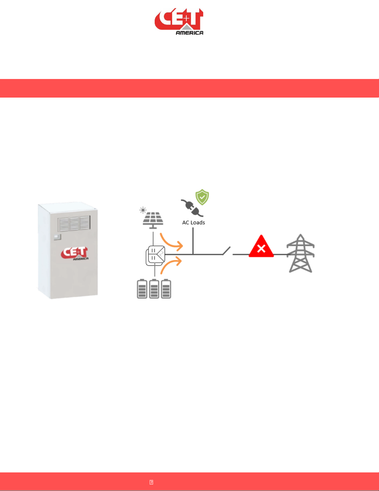
9. Microgrid Operation Overview –Islanding Switchgear Method
This is how the system shall be interconnected when using CE+ T supplied islanding switchgear:
Figure 3 - Microgrid Operation –Islanding Switchgear Method
9.1. Field Wiring:
The AC connection from Stabiliti will go into an AC distribution panel (not shown above) and then
into “Islanding Switchgear”. From there, it will connect to the grid. Note that the “power supply
and digital control signals will go from “Islanding switchgear” to one Stabiliti and then connection
to subsequent Stabiliti will be daisy chained from this Stabiliti. Note that the “Islanding
Switchgear” design may look different (look and feel) than the one shown in figure above. The
field connections and functionality will remain the same. This is the most recommended mode
of operation for all “on grid” applications.
9.2. System Startup –Initial Start of System:
The system must be set up when the grid is present. Upon interconnecting everything, the SEL
relay will engage 24 volts to the two digital signals connected to Stabiliti and at the same time it
will energize/close the Grid Interconnect Contactor (GIC). At this time the load is powered via
the grid. Now each stabiliti should be manually commissioned and brought online. Note that
Stabiliti’s AC port must be set in “FPWR” mode. When grid is present and SEL relay is not
commanding the Stabiliti to form the grid, Stabiliti will wait for a Customer Control System (CCS)
to send a power command to support the load.

9.3. Follow to Form Operation –Loss of Grid:
When the grid is lost, the SEL relay detects the loss of grid and notifies the Stabiliti to start getting
ready to form the microgrid. After this, SEL relay opens the GIC. Upon successful GIC operation,
SEL reports back to Stabiliti that its ok to form microgrid now. This whole process takes around
100 ms. Note that once Stabiliti are forming the grid, they will ignore power command sent by
CCS and will keep the loads on by appropriately taking power from the two DC ports.
The Stabiliti’s on board control systems are normally powered via the 480-vac connection. During
the “following to forming” transition, the UPS within the Islanding switchgear provides power to
keep the internal Stabiliti controls running.
9.4. Form to Follow Operation –Grid is Back:
When the grid is back, SEL ensures that the grid formed by Stabiliti is in sync (phase, voltage,
frequency) with the grid and upon successful sync, SEL relay closes the GIC and releases both
microgrid command signals from Stabiliti. This transition is almost seamless.
9.5. Application:
Using this method adds cost to the system but it greatly automates the microgrid function. A
customer control system will have to make no decision to enable any of “forming to follow” or
“follow to forming” transitions. This is best suited for all “on grid” applications.
9.6. Design Consideration:
Read through this full document and all applicable application notes, system manual, BESS
manual etc before proceeding. Note that for stabiliti to be able to reliably support microgrid, a
stable source of power, like batteries must be connected. Batteries can be paired with PV (on
the second DC port). Also note that load must be less than combined power output of the entire
system. For instance, if the loads that needs to be backed up is 90 kw, its advisable to use 4
instead of 3 Stabiliti.
10. Field Wiring –Power Supply
Islanding Switchgear has a UPS within it that requires to be powered via a standard outlet (120 volt for US
version and 230 volts for EU version). A standard three prong cable must be connected to “VAC in”
terminal block for the supply power.
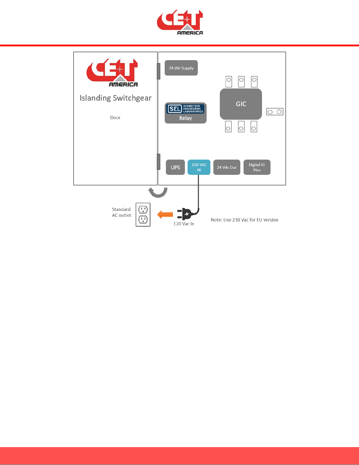
Figure 4 - Field Wiring –Islanding Switchgear Supply Power
11. Field Wiring –Utility and Load
During the time microgrid is active, the Stabiliti and loads must be isolated from the utility tie in
connection. To enable that, there is a “grid interconnect contactor” (GIC) within the Islanding Switchgear
solely controlled by the SEL relay (which is also within the Islanding Switchgear). Note that no coordination
from a site controller or a PMS is required for operation of SEL or the GIC. The utility and combined load
connections must be wired to the GIC as shown below:
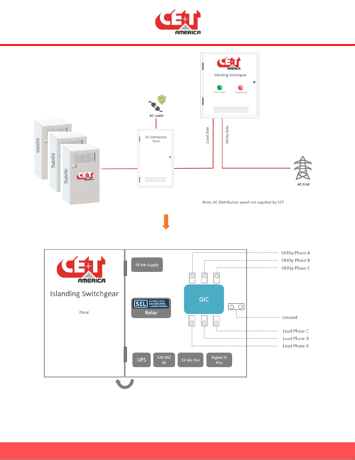
Figure 5 - Field Wiring - Utility and Load Side

12. Field Wiring –Stabiliti Supply Power
There are two ways to power Stabiliti’s control board. Through 480 VAC or using an external 24 Vdc power
supply. During microgrid operation, there is no 480 Vac supplied by Utility. So, to keep Stabiliti powered
through the “following to forming” transition, an external power supply source must be used. Islanding
Switchgear houses a UPS supported 24 Vdc power supply for the very same reason. Wiring is straight
forward as shown below:
Figure 6 - Field Wiring - Stabiliti Supply Power
13. Field Wiring –Stabiliti Control Wiring
There are two sets of digital control signal which are generated by the SEL namely “Island Command”
(Island CMD, Island CMD RTN) and “Island Acknowledge” (Island ACK, Island ACK RTN). These signals are
necessary for Stabiliti’s reliable microgrid operation. Wiring is daisy chained among all Stabiliti as shown
below:
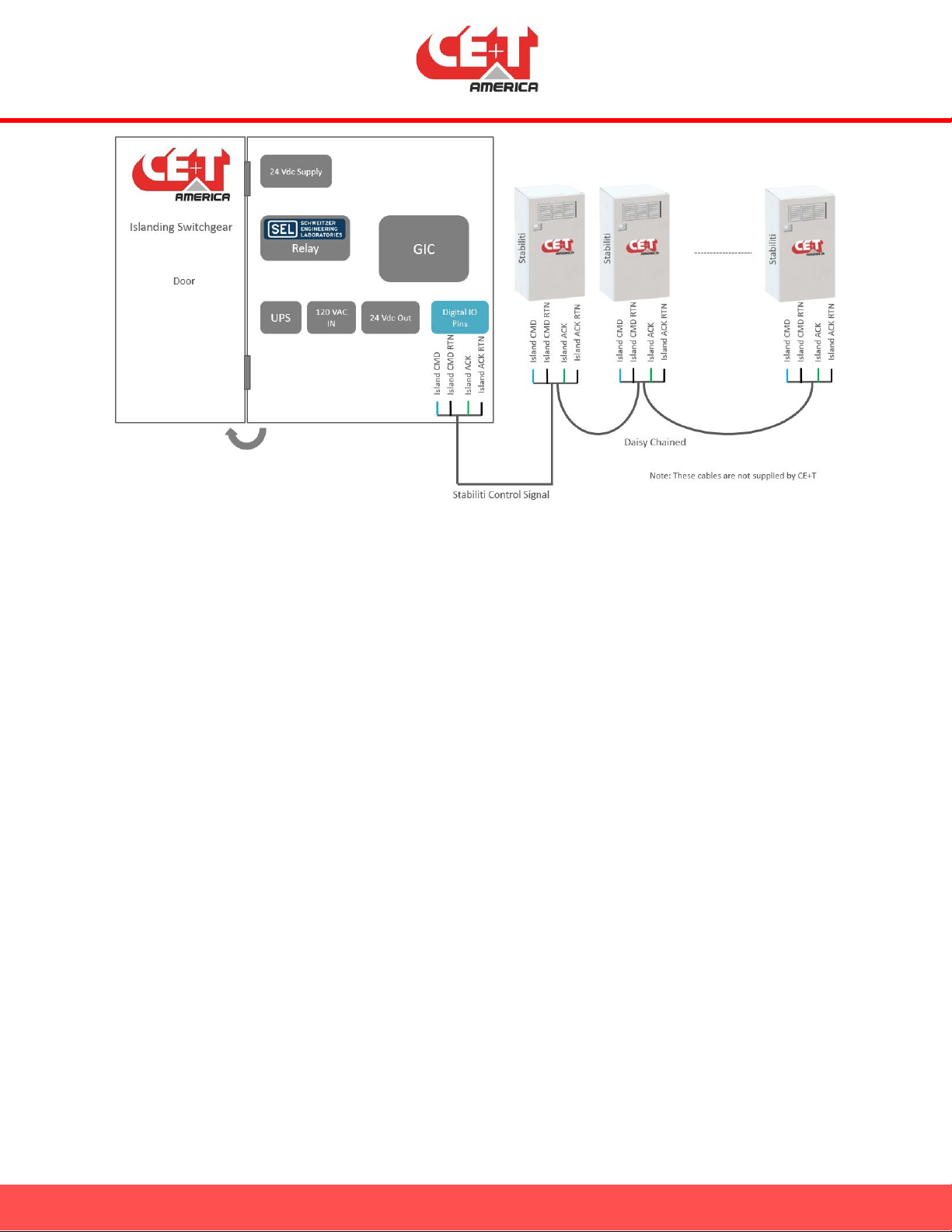
Figure 7 - Field Wiring - Stabiliti Control Wiring
14. Stabiliti Port Settings via Modbus
In addition to using Islanding Switchgear, Stabiliti must have correct AC port settings to be able to form
microgrid. For this, AC port must be set to FPWR or “Form Power” (modbus register 65, value of hex 502).
Note that merely setting AC port to FPWR does not force Stabiliti to form microgrid. “Island CMD” and
“Island ACK” must also be set right by Islanding Switchgear. In addition, Stabiliti’s link must be running.
This can be done either by setting “System Operation Mode” to “Manual” (register 267, a value of 0 and
then a value of 1 to register 263) or by setting “System Operation Mode” to “Auto” (register 267, a value
of 1). In Auto mode, link will start automatically if there are no faults in the system.
In addition, note that Islanding Switchgear also provides the 24 Vdc power supply for Stabilti to stay
powered through the “Following to Forming” transition.
15. Understanding Islanding Switchgear Panel LEDs
Note that there is no physical display on the Islanding Switchgear. There are two LEDs, one LED indicates
presence of grid voltage and the second one indicates whether the AC loads also have voltage (either via
grid or via Stabiliti supported microgrid) or not.
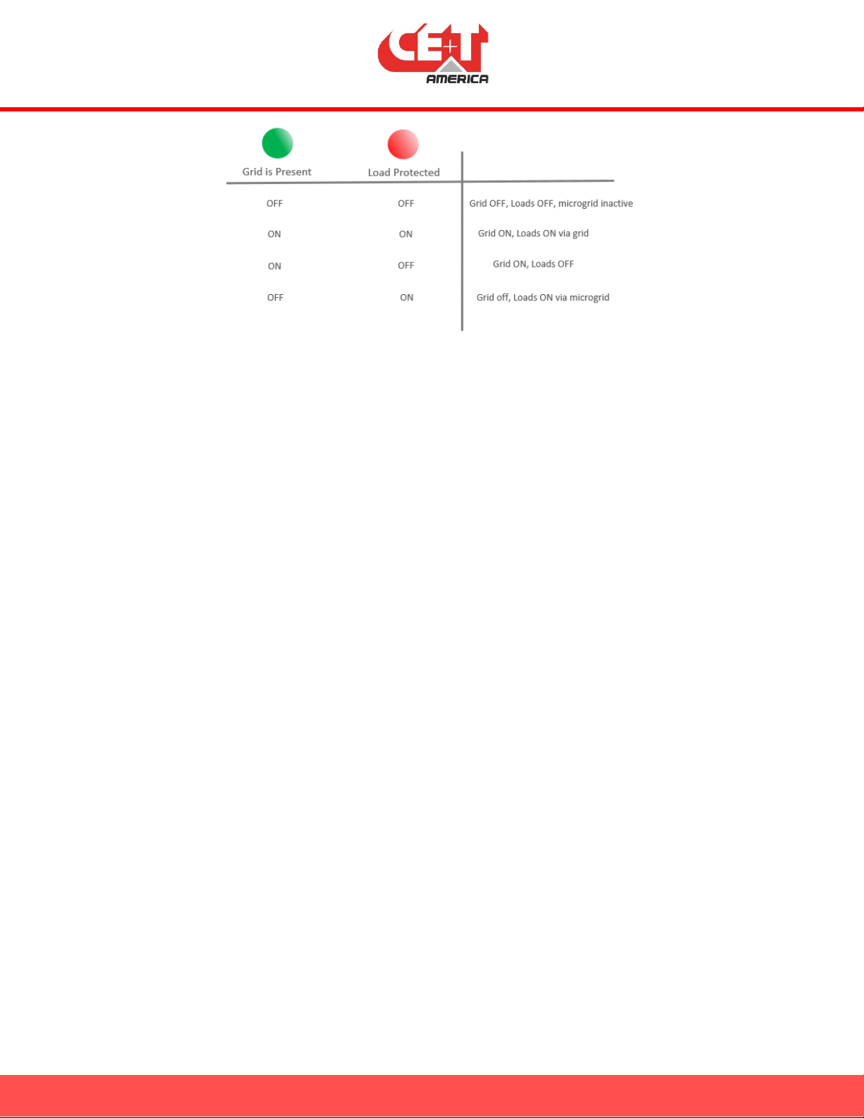
Figure 8 - Panel LED Status Description
16. Site Demonstration –Site Acceptance Tests (SAT)
Before performing a site demonstration, ensure following prerequisites are met:
•Everything is interconnected and installed as per manual, local NEC and NFPA codes
•Stabiliti’s are commissioned
•Batteries are sized appropriately. Note that batteries must be sized to support full load on their
own. For instance, if the load is 90 kw, ensure there are 4 stabiliti and multiple battery strings
rated to run at 100 kw discharge rate for the required amount of back up time.
•Batteries are commissioned as per vendor’s instructions and ready to charge/discharge. Leave the
SoC around 70 to 90% before starting.
•Load is sized appropriately
•A way to disconnect grid input to the Islanding Switchgear (AC disconnect, not supplied by CE+T).
The SAT setup should look like the one shown below:
The “colored” items (Site controller and utility disconnect switch) will be operated during these tests to
verify the complete operation of the system.

Figure 9 - Site Acceptance Test Setup
Follow the steps listed below:
Note that the two components that will be changed during the tests are the AC disconnect (open or close)
and Stabiliti’s AC setpoint (for the whole set up. So if the table below says 40 kw and if you have 4 stabiliti,
then each stabiliti gets a 10 kw setpoint)
Load size = 90 kw, Number of Stabiliti = 4 (120 kw), Battery Allowable Discharge rate = 100 kw.
Grid Status
(AC Disconnect Status)
Microgrid Status
AC Setpoint
Load Status
1
ON
OFF
0
Grid powered
2
ON
OFF
45 kw
45 kw powered via stabiliti, rest via grid
3
OFF/disconnect open
ON
45 kw
Microgrid powered
4
OFF/disconnect open
ON
0 kw
Microgrid powered
5
ON
OFF
0 kw
Grid powered
Ensure the LED status on the panel matches with actual system operation.

17. Black Start Operation
When the AC loads must be started from a completely off state and there is no grid present, Islanding
switchgear can be used to facilitate “Black Start”. To be able to successfully turn on ALL the connected
load, ALL Stabiliti must start synchronously at the same time. Even if one Stabilti fail to start, rest of the
Stabiliti may not be able to support the inrush current requirements of the load and the AC loads may
never turn on.
To seamlessly support black start, Islanding switchgear (ISG) has two toggle switches on the front. These
switches are available on 2nd generation Islanding Switchgear. During normal operation (when the black
start is not required), the switches must be left in the state shown below:
Figure 10 - Black Start - Toggle Switch State - Normal Operation
17.1. Stabiliti Control Power During Black Start
Note that when there is no grid present and when Stabiliti is not running (the LCD panel is on,
but Stabiliti is not actively forming microgrid), the source powering the Stabiliti’s control board
is a UPS within Islanding switchgear. This UPS is sized to support short duration power to
Stabiliti. During grid connected operation, this UPS charges its batteries via grid (120 volts
connection). When there is no grid for extended time, the batteries within this UPS may get
completely drained. So, ensure there is a way to power on ISG and charge UPS battery within
ISG. A portable Diesel genset can also be used for this. Budget 300 watts plus 120 watts for
each Stabiliti. So if there are two Stabiliti, you need 540 watts (plus 25% headroom).
Other manuals for Stabiliti 30C3 750/480
1
Table of contents


