Cetetherm Midi Compact TA DHWC Manual

DOC1314 Rev: 2020-06-01
Installation, service and operating instruction Cetetherm Midi Compact TA DHWC
Heating and domestic hot water substation for apartment houses (10-50 apts.)

This manual is published by Cetetherm.
Cetetherm can without further notice make changes and improvements to the content in this manual if it is necessary due to printing
mistakes, wrong information or changes in the hardware or software.
All these types of changes will be included in future release of the manual.
For additional on-line information, latest version of this manual please scan
the qr-code or use the link:
https://www.cetetherm.com/midicompact
QR-code:

Cetetherm Midi Compact TA
Installation, service and operating instruction
1
Contents
1General ..................................................................................................................................3
1.1 Comfort......................................................................................................................................................3
1.2 Installation .................................................................................................................................................3
1.3 Long-term security.....................................................................................................................................3
1.4 CE-marking................................................................................................................................................3
1.5 Information about the document................................................................................................................3
1.6 General warnings ......................................................................................................................................4
2Operating instructions..........................................................................................................5
2.1 Operation...................................................................................................................................................5
2.2 Safety equipment/inspection .....................................................................................................................5
3Product overview ..................................................................................................................6
3.1 Midi Compact TA .......................................................................................................................................6
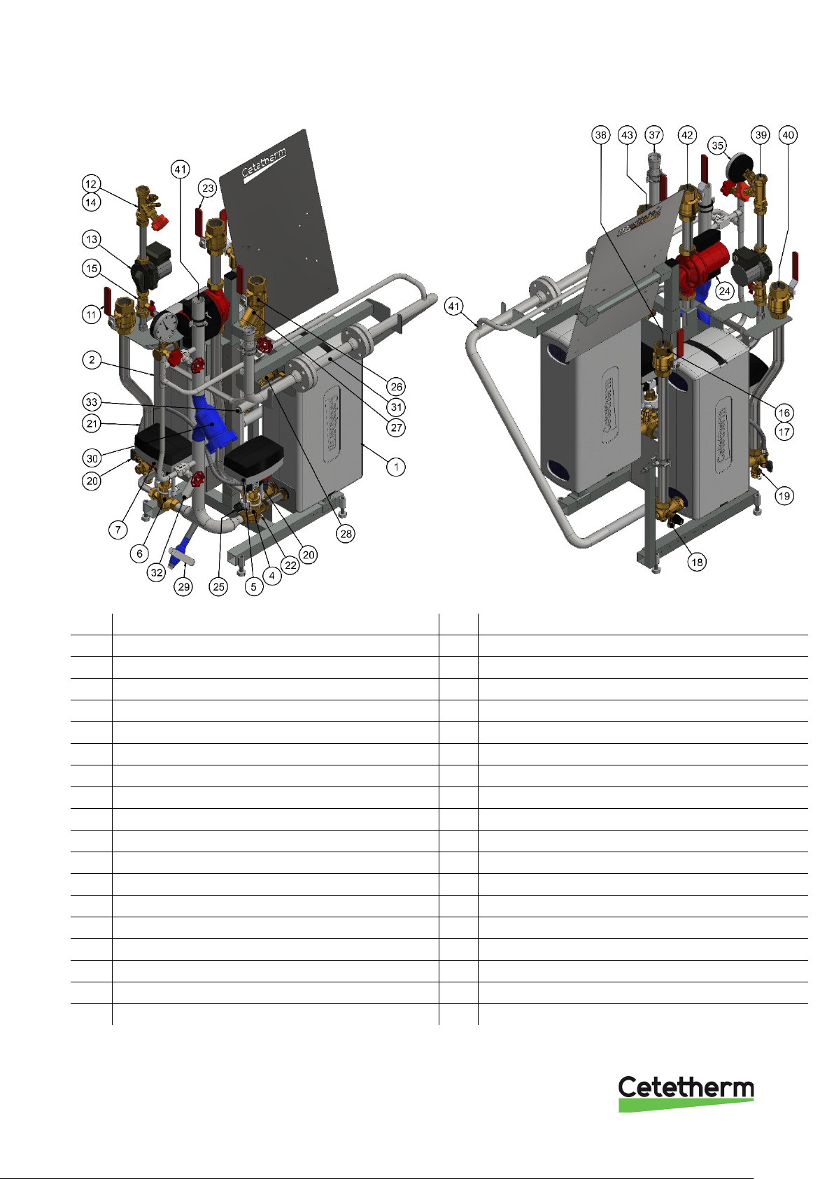
3.2 Product overview Midi Compact TA with vertical metering .......................................................................7
3.3 Product overview Midi Compact TA with horizontal metering ...................................................................8
4Installation.............................................................................................................................9
4.1 Unpacking..................................................................................................................................................9
4.2 Preparation ................................................................................................................................................9
4.3 Mounting....................................................................................................................................................9
4.4 Adjustments and settings for start up ..................................................................................................... 10
4.5 Dismantlement........................................................................................................................................ 10
4.6 Measure sketch Midi Compact ............................................................................................................... 11
4.7 Measure sketch Midi Compact with vertical metering ............................................................................ 12
4.8 Measure sketch Midi Compact with horizontal metering........................................................................ 13
5Schematic diagram, main components.............................................................................14
5.1 Midi Compact.......................................................................................................................................... 14
5.2 Midi Compact with vertical metering....................................................................................................... 15
5.3 Midi Compact with horizontal metering .................................................................................................. 16
6Pump settings and pump capacity ....................................................................................17
6.1 General................................................................................................................................................... 17
6.2 DHWC pump Grundfos UPSO 15-55, capacity...................................................................................... 17
6.3 Heating circuit pump Grundfos Magna3 25–100, settings and capacity................................................ 18
6.3.1 Heating circuit pump Grundfos Magna3 25-100, capacity ................................................................ 18
6.3.2 Grundfos Eye operating indications .................................................................................................. 18
7Service instructions............................................................................................................19
7.1 Service instructions, tap water ............................................................................................................... 19
7.1.1 Tap water temperature too low ......................................................................................................... 19
7.1.2 Tap water temperature too high ........................................................................................................ 19
7.1.3 Hot water temperature unstable........................................................................................................ 19
7.1.4 Noise in the DHWC system............................................................................................................... 20
7.2 Service instructions, heating system ...................................................................................................... 20
7.2.1 Heating system temperature too high or too low .............................................................................. 20
7.2.2 No heating ......................................................................................................................................... 20
7.2.3 Noise in the radiator system.............................................................................................................. 20
7.2.4 Heating temperature unstable........................................................................................................... 21
7.2.5 Heating system often needs topping up............................................................................................ 21
8Service actions for the installer .........................................................................................22
8.1 Check the function of the hot water valve and actuator ......................................................................... 22
8.2 Check the function of the heating actuator and valve ............................................................................ 23
8.3 Check DHWC pump ............................................................................................................................... 24
8.4 Check the volume take-up and pressure equalizing of the expansion vessel ....................................... 24
9Maintenance and repairs ....................................................................................................25
9.1 Cleaning the district heating strainer ...................................................................................................... 25
9.2 Clean the heating circuit strainer............................................................................................................ 26
9.3 Change the complete DHWC pump or pump components.................................................................... 26
9.4 Change the complete heating pump or pump components ................................................................... 27

Cetetherm Midi Compact TA
Installation, service and operating instruction
2
9.5 Change the actuator ............................................................................................................................... 27
9.6 Change the heating or hot water valve .................................................................................................. 28
9.7 Change the expansion vessel ................................................................................................................ 28
10 Options ................................................................................................................................29
10.1 Actuator .................................................................................................................................................. 29
10.2 4-point HB metering ............................................................................................................................... 29
11 Operation data and capacity ..............................................................................................30
11.1 Operation data Midi Compact 80............................................................................................................ 30
11.2 Operation data Midi Compact 100.......................................................................................................... 31
11.3 Operation data Midi Compact 160.......................................................................................................... 32
11.4 Operation data Midi Compact 200.......................................................................................................... 33
11.5 Technical data ........................................................................................................................................ 33

Cetetherm Midi Compact TA
Installation, service and operating instruction
3
1 General
Cetetherm Midi Compact is a complete, ready-to-install heating network substation for heating and hot water. It
is designed for buildings with a primary connection to a heating network. Cetetherm has years of experience in
heating network technology and has developed Midi Compact with well-planned pipe work and with all
components easily accessible for inspection and possible future servicing.
1.1 Comfort
Midi Compact has fully automatic temperature control for hot water. The hot water is controlled and maintained
at the desired temperature.
1.2 Installation
Before installation this manual must be read.
Well planned pipe work make installation very simple.
The Midi Compact is designed to be placed on the floor.
1.3 Long-term security
All the plates and pipes in the heat exchanger are made of acid-resistant stainless steel for long life. All
components are adjusted together and undergo thorough function testing in accordance with ISO 9001:2015
quality assurance system.
For future servicing requirements, all components are easily accessible and individually replaceable.
1.4 CE-marking
Midi Compact is CE-marked to certify that the substation conforms to international safety regulations. To
maintain the validity of the CE marking, only identical replacement parts must be used.
1.5 Information about the document
All pictures in this document are general images.
Midi Compact is available in different models and levels of equipment.

Cetetherm Midi Compact TA
Installation, service and operating instruction
4
1.6 General warnings
The installation work must be carried out by an authorized installation contractor. Before the system
is taken into operation, it must be pressure tested in accordance with relevant regulations.
The temperature and the pressure of the district heating water are very high. Only duly qualified
technicians can work with the district heating substation. Incorrect operation may cause serious
personal injury and result in damage to the building.
If the hot water temperature is set too high, people may be scalded. If the hot water temperature is
set too low, unwanted bacteriological growth may occur in the hot water system. This can result in
serious personal injury.
Parts of the Midi Compact may get very hot and should not be touched.
Before the substation is connected to the electrical supply, make sure that the secondary heating
system is topped up with water. Starting up the system without water will damage the circulation
pump.
When starting up the district heating substation: To avoid the risk of scalding, make sure that no-
one draws any hot water until the hot water temperature has been adjusted.
Start district heating circulation by first opening the valve in the district heating supply and then
return lines, to avoid pollutions in the system. Open the valves slowly to avoid pressure surges. Do
the same way with the heating circuit, first open the valve for heating return then supply.
Do not shut of the electrical supply to the operator control panel. This will damage the circulation
pump, valves, actuators etc.
The heating station should be placed in a locked space, non-accessible for unauthorized personnel.

Cetetherm Midi Compact TA
Installation, service and operating instruction
5
2 Operating instructions
2.1 Operation
The temperature and pressure of the incoming heating network water from the culvert network are very high.
For this reason, only the heat from this water is used. The heating network water does not enter the heating
and hot water systems of the building.
The heat from the heating network water is transferred to the heating and hot water systems of the building in
the heat exchangers. The heat is transferred through thin plates of acid-resistant stainless steel which keep the
heating network water completely separated from the systems in the building.
Midi Compact has automatic temperature control for hot water. The hot water temperature is controlled by a
temperature control system which is set to about 55 ºC.
After adjustment, the Midi Compact operates completely automatically. However, in hard water areas it is
advisable to be attentive and to remedy any faults in good time if the temperature of the hot water is too high;
otherwise the risk of lime deposits in the heat exchanger may increase.
2.2 Safety equipment/inspection
•Daily inspection to check for leaks from pipes or components.
•Weekly inspection to make sure that the operation of the heating and hot water control systems is
stable and that the temperature does not fluctuate. Temperature hunting causes unnecessary wear of
valves, actuators and heat exchangers.
•Every three months check the safety valves and the pressure in the heating system.
To check the operation of a safety valve, turn its wheel until water escapes from the waste pipe of the valve,
then close the wheel quickly. Occasionally a safety valve may open automatically to release excess pressure.
After a safety valve has been open it is important that it closes properly and does not drip.
Hot water temperature in apartments or one family houses can be set to about 55°C. If the temperature is set
too high, there is a risk of scalding. Setting the hot water temperature too low may result in unwanted
bacteriological growth in the hot water system.
The heating system is topped up via the topping up valve. Be sure to close the valve when the correct pressure
is reached. The water used to top up the system contains oxygen and may cause corrosion in the system. For
this reason, the system should be topped up as seldom as possible, at most once
If a joining must be loosened and then re-installed, for example when installing the substation or when
replacing a strainer unit, the joining gaskets should be exchanged to prevent leaks.

Cetetherm Midi Compact TA
Installation, service and operating instruction
6
3 Product overview
3.1 Midi Compact TA
Picture 1
1
Heat exchanger heat
21
Hose
2
Heat exchanger DHW
22
Draining valve, heat supply
4
Control valve, heating
23
Shut off valve, heat supply
5
Actuator, heating
24
Pump, heating
6
Control valve, DHW
25
Safety valve, heating
7
Actuator, DHW
26
Shut off valve, heat return
11
Shut off valve, DHW
27
Strainer, heat return
12
Balancing valve, DHWC
28
Connection, expansion vessel
13
Pump, DHWC
29
Draining valve, DH-Supply
14
None return valve, DHWC
37
DH Return
15
Shut off valve, DHWC
38
CW
16
Shut off valve, CW
39
DHWC
17
None return valve, CW
40
DHW
18
Safety valve, CW
41
DH supply
19
Draining valve, DH-Supply
42
Heat Supply
20
Topping up
43
Heat Return

Cetetherm Midi Compact TA
Installation, service and operating instruction
7
3.2 Product overview Midi Compact TA with vertical metering
Picture 2
1
Heat exchanger heat
23
Shut off valve, heat supply
2
Heat exchanger DHW
24
Pump, heating
4
Control valve, heating
25
Safety valve, heating
5
Actuator, heating
26
Shut off valve, heat return
6
Control valve, DHW
27
Strainer, heat return
7
Actuator, DHW
28
Connection, expansion vessel
11
Shut off valve, DHW
29
Draining valve, DH-Supply
12
Balancing valve, DHWC
30
Strainer, DH-Supply
13
Pump, DHWC
31
Heat meter dummy
14
None return valve, DHWC
32
Connection energy meter sensor primary supply
15
Shut off valve, DHWC
33
Connection energy meter sensor primary return
16
Shut off valve, CW
37
DH Return
17
None return valve, CW
38
CW
18
Safety valve, CW
39
DHWC
19
Draining valve, DH-Supply
40
DHW
20
Topping up
41
DH supply
21
Hose
42
Heat Supply
22
Draining valve, heat supply
43
Heat Return

Cetetherm Midi Compact TA
Installation, service and operating instruction
8
3.3 Product overview Midi Compact TA with horizontal metering
Picture 3
1
Heat exchanger heat
24
Pump, heating
2
Heat exchanger DHW
25
Safety valve, heating
4
Control valve, heating
26
Shut off valve, heat return
5
Actuator, heating
27
Strainer, heat return
6
Control valve, DHW
28
Connection, expansion vessel
7
Actuator, DHW
29
Draining valve, DH-Supply
11
Shut off valve, DHW
30
Strainer, DH-Supply
12
Balancing valve, DHWC
31
Heat meter dummy
13
Pump, DHWC
32
Connection energy meter sensor primary supply
14
None return valve, DHWC
33
Connection energy meter sensor primary return
15
Shut off valve, DHWC
34
Connection 3-point HB metering
16
Shut off valve, CW
35
Pressure gauge connection
17
None return valve, CW
37
DH Return
18
Safety valve, CW
38
CW
19
Draining valve, DH-Supply
39
DHWC
20
Topping up
40
DHW
21
Hose
41
DH supply
22
Draining valve, heat supply
42
Heat Supply
23
Shut off valve, heat supply
43
Heat Return

Cetetherm Midi Compact TA
Installation, service and operating instruction
9
4 Installation
4.1 Unpacking
•Remove the transport packaging and check that the product has not been damaged in transit and that
the consignment agrees with the specifications.
•When lifting the unit, take care not to apply stress to pipes and heat exchangers as this may weaken
them. Lift the unit in the frame; avoid lifting the unit by holding the heat exchangers. Use pallet lift
where applicable, if using back straps these should be attached to the substructure of the substation.
Note: Risk of injury lifting heavy objects.
4.2 Preparation
•Choose a suitable installation area in accordance with official regulations.
The system may generate sounds during operation caused by pumps, regulators systems, flows etc.
This should be taken into consideration during installation of the unit, so that possible operational
sounds affect the surroundings as little as possible.
•Check the applicable regulations of the district heating supplier. The available differential pressure
should be at least 100 kPa and at most 600 kPa.
Where the differential pressure is higher, a differential pressure controller should be added to the
installation.
•Flush heating and hot water systems.
4.3 Mounting
•Place the substation so that connections, adjustment equipment and safety valves are easily
accessible.
•Mount the shutoff valves on district heating supply and return. Shutoff valves are not supplied.
•Connect the pipe works to the connection points, see 4.6-4.8.
•When executing hot work on or close by the substation, all incendiary components should be
demounted and removed.
•With supply temperatures above 100°, it is recommended that the actuator is tilted or put down.
Picture 4
•Take rules and instructions regarding hot work into account.
•Connecting pipes shall be suspended so that their weight does not stress the unit.
•All connecting pipes within and connecting to the units system shall be insulated according to
standards and regulations.
•Drainage pipes from safety valves must be taken to a floor gully.
•Energy meters must be installed at a prepared location, replacing a gauge block, or following the
instructions of the energy supplier.

Cetetherm Midi Compact TA
Installation, service and operating instruction
10
•Retighten all connections, including those made at the factory. If connections need retightening after
the installation has been taken into service, the system should be depressurised before retightening. If
the system is not depressurised before retightening, gaskets will be damaged.
•Required expansion volume shall be installed and provided with adequate pre-charge before start up.
•Remount plugs in drain valves after possible draining of circuit.
4.4 Adjustments and settings for start up
•Open up incoming cold water supply and fill the service water and heating circuits, bleeding off any
trapped air.
•Check the operation and opening pressures of the safety valves.
•Adjust the hot water temperature by having a hot water tap open at normal flow rate for a time.
Measure the temperature at the draw-off point with a thermometer. The temperature should be
approximately 55°C. It takes about 20 seconds to get stable tap water temperature. See
troubleshooting chart for adjusting hot water temperature, 7.1.1 Tap water temperature too low.
NOTE: Make sure that no cold water is mixed with hot water while making this adjustment.
•Start the heating circulation pump at the strongest flow setting during some minutes. The pressure
should be at least 1000 kPa during winter and at least 600kPA during summer.
•Set the pump capacity of the heating circulation pump and the DHWC-pump according to chapter
6 Pump settings and pump capacity. Use the lowest setting that manages the heating demand for best
electrical efficiency.
•The property owner must be informed on how to operate, adjust and maintain the unit. It is overly
important to inform about the safety systems and the risks associated with the high pressure and
temperature of the district heating systems water supply.
4.5 Dismantlement
When the time comes for the substation to be dismantled and scrapped it must be disposed of in the correct
manner in accordance with local or national regulations.

Cetetherm Midi Compact TA
Installation, service and operating instruction
11
4.6 Measure sketch Midi Compact
Picture 5

Cetetherm Midi Compact TA
Installation, service and operating instruction
12
4.7 Measure sketch Midi Compact with vertical metering
Picture 6

Cetetherm Midi Compact TA
Installation, service and operating instruction
13
4.8 Measure sketch Midi Compact with horizontal metering
Picture 7

Cetetherm Midi Compact TA
Installation, service and operating instruction
14
5 Schematic diagram, main components
5.1 Midi Compact
Picture 8

Cetetherm Midi Compact TA
Installation, service and operating instruction
15
5.2 Midi Compact with vertical metering
Picture 9

Cetetherm Midi Compact TA
Installation, service and operating instruction
16
5.3 Midi Compact with horizontal metering
Picture 10

Cetetherm Midi Compact TA
Installation, service and operating instruction
17
6 Pump settings and pump capacity
6.1 General
Mini Compact is equipped with two circulation pumps, one for the hot water circulation, DHWC-pump, and one
for the heating circuit.
The DHWC pump is a traditional three speed circulation pump. The DHWC pump has a switch where the
speed/capacity can be set.
The circulation pump for heating circuit is a pressure-controlled pump.
6.2 DHWC pump Grundfos UPSO 15-55, capacity
Picture 11
Picture 12

Cetetherm Midi Compact TA
Installation, service and operating instruction
18
6.3 Heating circuit pump Grundfos Magna3 25–100, settings and capacity
The pumps have been factory-set to AUTOADAPT without automatic night setback.
AUTOADAPT (factory set)
•Recommend control mode for most heating systems.
•Automatically adjusts the pump to actual system characteristics.
•Ensures minimum energy consumption and a low noise level.
•Reduced operating costs and increased comfort.
6.3.1 Heating circuit pump Grundfos Magna3 25-100, capacity
6.3.2 Grundfos Eye operating indications
Grundfos Eye
Indication
Cause
No lights are on. The power is off.
The pump is not running.
Two opposite green indicator lights
running in the direction of rotation
of the pump.
The power is on.
The pump is running
Two opposite green indicator lights
are permanently on.
The power is on.
The pump is not running.
One yellow indicator light running
in the direction of rotation of the
pump.
Warning.
The pump is running.
One yellow indicator light is
permanently on.
Warning.
The pump has stopped.
Two opposite red indicator lights
flashing simultaneously.
Alarm.
The pump has stopped.
One green indicator light in the
middle is permanently on in
addition to another indication.
Remote-controlled.
Table of contents
Other Cetetherm Water Heater manuals
Popular Water Heater manuals by other brands

State Water Heaters
State Water Heaters SCI 10 SOMS Service parts list

Webasto
Webasto Mazda 3 MPS installation instructions

Bulldog Security
Bulldog Security 40861-EU/UK instructions

Navien
Navien NPE-180A Quick installation guide

Noritz
Noritz GQ-2857WX-F US installation manual

Webasto
Webasto Thermo Top E installation instructions

Rheem
Rheem RTH-53XN Specification sheet

Rain Harvesting
Rain Harvesting TASS20 Installation and specification guide

Haws
Haws 9326 Installation, operation and maintenance manual

Bradford White
Bradford White Commercial Energy Saver Gas Millivolt Specifications

HTP
HTP Superstor Ultra SSU CB Series manual

Unical
Unical DUA plus BTN 28 Installation and user instruction manual