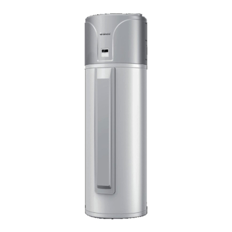
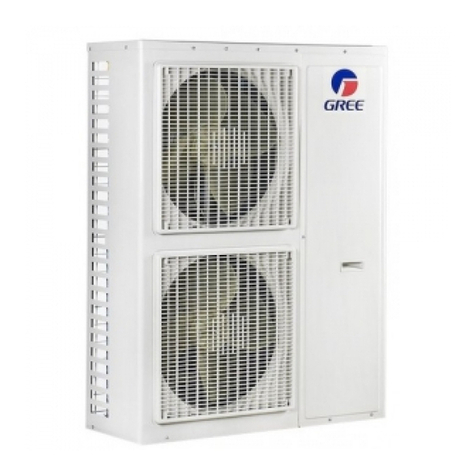
Gree GRS-Cm28/NaA-M User manual

CIRCULATINGAIR SOURCEHEAT PUMP
WATERHEATERSERVICEMANUAL
T1/R410A/50Hz
(GC201510 –ІІ)

Contents
CHAPTER ⅠPRODUCT INTRODUCTION............................................................1
1. INTRODUCTION OF UNIT .......................................................................................................................... 1
2. BASIC WORKING PRINCIPAL .................................................................................................................... 2
3. BASIC PARAMETERS OF UNIT................................................................................................................... 4
4. OPTIONAL FITTINGS................................................................................................................................. 5
CHAPTER ⅡINSTALLATION..................................................................................6
1. INSTALLATION FLOW CHART.................................................................................................................... 6
2. PREPARATION BEFORE INSTALLATION...................................................................................................... 6
3. INSTALLATION FOR MAIN UNIT OF WATER HEATER................................................................................ 10
4. DESIGN OF WATER SYSTEM.................................................................................................................... 13
5. INSTALLATION AND HEAT INSULATION FOR PIPELINES OF WATER SYSTEM............................................. 19
6. ELECTRIC INSTALLATION ....................................................................................................................... 34
7. INSTALLATION OF COMMUNICATION SYSTEM......................................................................................... 41
8. CHARGING OF REFRIGERANT ................................................................................................................. 43
CHAPTER ⅢDEBUGGING AND OPERATION...................................................46
1. DEBUGGING FLOW CHART..................................................................................................................... 46
2. SAFETY NOTICES ................................................................................................................................... 46
3. PRE-DEBUGGING PREPARATIONS............................................................................................................ 47
4. DEBUGGING OPERATION........................................................................................................................ 50
5. UNIT FUNCTION SETTINGS..................................................................................................................... 53
CHAPTER ⅣMAINTENANCE................................................................................56
1. ERROR CODE ......................................................................................................................................... 56
2.TROUBLESHOOTING ............................................................................................................................... 59
3. MAINTENANCE OF KEY PARTS ............................................................................................................... 66
4. UNIT EXPLOSION VIEWAND PARTS LIST................................................................................................ 90
CHAPTER ⅤUNIT MAINTENANCE................................................................... 102
1. DAILY OPERATION AND MAINTENANCE .............................................................................................. 102
2. CLEANING OF SYSTEM ......................................................................................................................... 102
Chapter ⅠProduct Introduction(1. Introduction of Unit)
1
Chapter ⅠProduct Introduction
1. Introduction of Unit
1.1 Product Overview
GRS-Cm28/NaA-M GRS-Cm28/NaA1-M
GRS-Cm36/NaA-M GRS-Cm36/NaA1-M
1.2 Operating Range of Unit
Product operation range
Item
Outdoor ambient temperature
Operation range for generating hot water
-26~46℃
GRS-Cm53/NaA-M、GRS-Cm53/NaA1-M

Chapter ⅠProduct Introduction(2. Basic Working Principal)
2
2. Basic Working Principal
2.1 Introduction of Working Principal
Backwater pipe
Condenser Evaporator
Fan
Air source energy input
Electric energy input
Electronic
expansion
valve
Strainer
Compressor
Water supply pipe
Water
tank
Inlet pipe of cold water
Bushing condenser
Exit pipe of hot water
Gas-liquid separator
The water heater starts to work after being energized, and then enters into heating. After the
low-temperature and low-pressure refrigerant gas is absorbed by compressor, it will be
compressed to be high-temperature and high-pressure gas, and then it enters into heat
exchanger of water side to conduct heat exchange with water, through which the refrigerant
becomes liquid, and then the liquid refrigerant enters into the heat exchanger of air side via
depressurization and cooling of electronic expanding valve, it will conduct heat exchange with the
ambient air inside the heat exchanger of air side; after being evaporated to be low-temperature
and low-pressure refrigerant gas, it will return to the compressor and enter into the next cycle. At
the same time, the water inside the heat exchanger of water side which for conducting heat
exchange with refrigerant is heated and will flow to thermal insulating water tank by the driving of
water pump.

Chapter ⅠProduct Introduction(2. Basic Working Principal)
3
2.2 Name and Main Function of Different Parts
No.
Name
Main Function
1
Compressor
Acting as the heat of water heater system, compress the
refrigerant to be high-temperature and high-pressure gas, promote
the flowing of refrigerant inside the system.
2
Oil temperature heating belt of
compressor
Under stand-by status, keep the oil temperature of compressor;
ensure the reliability for restarting the unit.
3
Pressure switch
When the pressure of refrigerant excesses the operate value of
pressure switch, it will feed back to stop the operation of unit, so as to
protect the compressor.
4
4-way valve
It is used for the transformation between heating and defrosting
of system.
5
Heat exchanger of evaporator
When the refrigerant enters into evaporator and conducts heat
exchange with air, the heat exchanger of evaporator will absorb the
energy from air for the unit.
6
Fan
Enhance the heat exchange of evaporator.
7
Defrosting temperature sensor
For defrosting inspection.
8
Electronic expanding valve
On the one hand is for throttle and depressurization of
high-pressure liquid refrigerant, ensuring the pressure difference
between condenser and evaporator; on the other hand is for
adjusting the flow volume of refrigerant entering into evaporator, so
as to adapt to the variation of heat load of evaporator and ensure
steady operation of cooling device.
9
Gas-liquid separator
For separating gas and liquid to prevent the compressor from
being operated under humid environment.
10
Double pipe condenser
The high-temperature and high-pressure gas discharged from
compressor will release heat inside the double pipe heat exchanger
to heat the water.

Chapter ⅠProduct Introduction(3. Basic Parameters of Unit)
4
3. Basic Parameters of Unit
Model
GRS-Cm28/NaA-M
GRS-Cm28/NaA1-M
GRS-Cm36/NaA-M
GRS-Cm36/NaA1-M
GRS-Cm53/NaA-M
GRS-Cm53/NaA1-M
Product Code
ER01000150
ER01000180
ER01000160
ER01000190
ER01000170
ER01000200
Hot water
mode
Heating capacity
kW
28
36
53
Heating Power Input
kW
7.3
9.3
13
Heating Current Input
A
13.9
16.9
26
Nominal Water Output
L/h
602
775
1140
Rated Input
kW
10.1
13.2
19
Rated current Input
A
20
24
38
Set temperature
℃
defaulted at 50℃. 30℃~60℃adjustable (water tank temperature)
Power
380-415V 3N~50Hz
Refrigerant
Name
R410A
R410A
R410A
Refrigerant charge
volume
kg
4.2
4.2
5.9
Compressor
Type
Totally-enclosed scroll compressor
Q‟ty
Set
1
1
1
Heat
exchanger
Wind side
Finned type heat exchanger
Water side
Shell-and-tube heat exchanger
Fan
Type
Low noise axial flow fan
Air discharge type
Top air discharge
Airflow(ambient
temperature 25℃)
m3/h
11400
11400
12400
Water system
Circulating Water
Flow
m3/h
4.8
6.2
9.2
Water pressure
kPa
70
130
70
Maximum bearing
pressure
MPa
0.8
0.8
0.8
Diameter of air inlet
pipe and air outlet
pipe
in
G 1-1/4
G 1-1/4
G 2
Outline
dimension
W×D×H
mm
930×800×1605
930×800×1605
1340×800×1605
Packing size
W×D×H
mm
1010×865×1775
1010×865×1775
1420×880×1775
Noise
dB(A)
≤67
≤67
≤67
Unit net weight
kg
243、242
260、262
358、364
①Data in the above table are based on the following test conditions:outdoor ambient
temperature: 20℃DB/15℃WB; initial water temperature: 15℃; final water temperature:55℃;
Voltage: 380V 3N~50Hz.
②Applicable range: ambient temperature range is -26°C~46°C.
③The above pressure values all belong to gauge pressure.
④Noise is tested in the semi-silencing room. The actual noise will be a little higher in the
actual operation environment.

Chapter ⅠProduct Introduction(4. Optional Fittings)
5
⑤Circulating water flow means the rated flow during the heating operation. When selecting
the water pump model, it shall refer to the flow after overcoming the water resistance, that is, the
flow of corresponding delivery lift, rather than the maximum flow labeled in the nameplate of water
pump.
⑥The listed water resistance refers to the water resistance under rated working conditions. If
the ambient temperature and water inlet temperature are different, unit‟s hot water output will be
changed accordingly, and the water resistance may be different from the listed value.
⑦If the specification is changed due to the product improvement, please refer to the
nameplate.
⑧The system reliability and the different water temperature requirement under different water
temperature are considered for this product and limit the maximum water tank temperature for
stop operation.
The curve is as below:
Curve of maximum water tank temperature for stop operation with the change of ambient temperature
Ambient
temperature/℃
Tank
temperature/℃
Ambient
temperature/℃
Tank
temperature/℃
Ambient
temperature/℃
Tank
temperature/℃
-26
53
-1
58
24
60
-25
53
0
58
25
60
-24
53
1
58
26
59
-23
53
2
58
27
59
-22
53
3
59
28
58
-21
54
4
59
29
58
-20
54
5
59
30
58
-19
54
6
59
31
57
-18
54
7
60
32
57
-17
54
8
60
33
57
-16
55
9
60
34
56
-15
55
10
60
35
56
-14
55
11
60
36
56
-13
55
12
60
37
55
-12
55
13
60
38
55
-11
56
14
60
39
55
-10
56
15
60
40
54
-9
56
16
60
41
54
-8
56
17
60
42
54
-7
57
18
60
43
53
-6
57
19
60
44
53
-5
57
20
60
45
53
-4
57
21
60
46
52
-3
57
22
60
-2
58
23
60
4. Optional Fittings
Circulating air source heat pump water heater includes the following optional fittings:
Supplying Contents
Model
Remarks
Packaged Attachment
CF122
The packaged attachment contains operating
instruction manual、liquid level switch、display
board Z26301K、sensor sub-assy and so on.

Chapter ⅡInstallation(1.Installation Flow Chart)
6
Chapter ⅡInstallation
1.Installation Flow Chart
Submit the design draft
Selection of material
Examine and verify the on-site installation position
Install water tank Install outdoor unit
Install water-side pipelines
and valves
Heat insulation
connect water tank and outdoor unit
Connect power cord and communication wire
Debugging of unit
Completion work chart
Deliver operating instruction manual
2. Preparation Before Installation
2.1 Matters Need Attention During Installation
2.1.1 Safety requirements for installation and construction
Warning! Before construction, all the constructors must have had the safety education
and have passed the safety examination. Once there is violating behavior, the constructor should
bear related liabilities.

Chapter ⅡInstallation(2. Preparation BeforeInstallation)
7
Warning! During the installation and construction, personal and property safety must
be placed in the first place. During the construction, constructors must abide by the national
related safety criterion to avoid personal injury or property loss.
2.1.2 Importance of installation
Water heater adopts direct evaporative type cooling system, which has high requirement for
the cleanliness and dryness of inner pipelines of the system. When manufacturing and laying
pipelines in the construction site,
No.
Installation Problem
Existing Influence
1
Incorrect connection of PPR pipeline
and then leads to blockage
The unit enters into protection mode and does not yield hot
water; or the water flow is too small to satisfy the using
demand.
2
Cooling water inlet pipe has not been
installed with filter and then leads to
blockage
3
The installation position of outdoor unit is
in bad ventilation condition
When the ambient temperature is high, the unit is likely to arise
high-pressure protection and then close down.
4
The outdoor unit has not been fixed
There will be large noise during the operation of unit
5
Bad heat insulating condition of
pipelines or there is no heat insulation
for pipelines
There will be great loss of heat, the water temperature cannot
satisfy the using demand.
6
Water pressure of tap water is not great
enough, or water pressure of tap water
is too high that there is no corresponding
remedial measure
The unit cannot operate normally, which may cause complaint
of client.
7
Improper protection of control
communication wire
The communication wire appears short circuit or open circuit,
the unit has communication error and cannot be started up.
8
Has not well communicated with user
and has not installed return pipe.
The hot water cannot yield until long time of discharging cooling
water
2.1.3 Professional coordination
The installation of product can hardly do without the coordination with the construction,
structure, electric, water supply and drainage, fire control, decoration and related conditions.
Layout of pipeline should keep away from the fire control automatic spray header, and the
pipelines should be properly arranged according to the layout of electric, lighting, and decoration.
1)Reserve holes and sleeving;
2)Reserve installing space for main unit and water tank, prepare the basis; installation
position of main unit should satisfy the requirements for bearing, ventilation and maintenance of

Chapter ⅡInstallation(2. Preparation BeforeInstallation)
8
unit;
3)If there are no reserving holes, the holes can be drilled, but it is not allowed to drill on the
spandrel girder or load bearing wall.
4)Pipelines for cooling water, hot water and return pipe should be prearranged, and should
reserve interfaces for the pipelines of cooling water, hot water and return pipe;
5)The indoor hot water pipelines should be kept in good heat insulation.
6)Reserve special route for water heater, type of power source and electric capacity should
satisfy the using requirements;
7)Check if the power cord and air switch satisfy the requirement of unit, whether they comply
with local safety criterion and law;
8)Check if the regional power supply quality (including voltage pulsation and interference
wave) can satisfy the requirements of local safety criterion and law; if not, please coordinate and
solve the problem.
2.2 On-site Examination and Verification of Design Draft
Installation personnel should carefully read the designing plan and draft provided by designer,
and conduct verification and examination according to on-site conditions, and propose reasonable
revised suggestion in time.
Confirmation sheet of construction design draft for examination and verification:
No.
Contents for Confirmation
Result
1
Check if the installation position of unit has satisfied the space requirement for
heat exchanger and maintenance
2
Check if the pipe diameter of water pipe has satisfied the operating requirement
of unit
3
Check if there is return pipe
4
Check if there is auxiliary electric heating equipment
5
Check if the power cord specification and type can satisfy the designing
requirement of unit
6
Check if the manufacture, total length and control mode of control wire can satisfy
the designing requirement of unit
7
Check if the design of reserving interface for water tank can satisfy the
connection and control requirements of unit
Notes: The installation personnel must conduct strictly abide by the design draft.
During the installation, if the actual installing situation cannot satisfy the designing requirement,

Chapter ⅡInstallation(2. Preparation BeforeInstallation)
9
installation personnel should seek confirmation from the designer and make a Design Alteration
Record in written form.
2.3 Selection of Installation Materials
2.3.1 Notices for Selecting Installation Materials
1)If the brand and dimension of installation materials are designated, users should purchase
the materials according to the requirements; if there are no designated installation materials, the
materials purchased by users must be in accordance with the local criterion and quality
requirement.
2)The materials, equipments and appliances for installation should have certificate of
qualification or inspection report;
3)Products with fire control requirement should have fire control inspection certificate and
should comply with local and related compulsory standards;
4)If it is required to use eco-friendly materials, all the materials must comply with the local
eco-friendly requirements and should provide related certificates.
2.3.2 Requirements for selecting Installation Materials
It is suggested to use PPR pipe as the hot water system pipelines. PPR pipes can be easily
installed and connected, the material and fittings can be expediently purchased; it will not produce
welding slag or other waste materials during the installation, and will not product rust and course
bad water quality during the using of unit.
The design pressure of polypropylene random copolymer pp-r (PP-R) pipeline system should
not be greater than 1.0 MPa, and design temperature should not be less than 0℃and should not
be higher than 70℃.
1)Heat-insulating materials and their products must have product quality6 inspection report
and leave factory certificate of qualification.
2)Heat insulating material is suggested to use flexible close type foaming rubber and plastic
heat insulating material;
3)Burning rating of heat insulating material is required to be B1 level orA level;
4)Refractoriness of heat insulating should not be less than 120℃.

Chapter ⅡInstallation(3. Installation for Main Unit of Water Heater)
10
Communication wire and control wire should strictly abide by the requirement that should use
the originally provided twisted-pair or STP of unit. The standard length of communication wire
between unit and wired controller is 8 meters, the maximum connecting length should not be more
than 20 meters.
The power cord must use copper conductor that should comply with related local conductor
standard, and satisfy current-carrying capacity requirement of unit. For specific selection of wire
diameter please refer to the contents of Chapter Six.
3. Installation for Main Unit of Water Heater
3.1 External Dimensions and Size of Installation Holes
(1) External dimensions and size of installation holes for GRS-Cm28/NaA-M 、
GRS-Cm28/NaA1-M、GRS-Cm36/NaA-M、GRS-Cm36/NaA1-M: Unit: mm
(2) External dimensions and size of installation holes for GRS-Cm53/NaA-M 、
GRS-Cm53/NaA1-M: Unit: mm

Chapter ⅡInstallation(3. Installation for Main Unit of Water Heater)
11
3.2 Selection of Installation Position
1)The installation position must be strong enough to bear the weight of water heater, and the
operating noise, discharging air, and condensate water shall not affect the neighbors.
2)The unit should not be installed in the place with flammable and combustible materials or
flammable and combustible gases.
3)The unit should not be installed in the place with corrosive gas, severe dust, or salt mist,
etc.
4)The unit should be installed in the place where has good ventilation and has adequate
space for air inlet and maintenance; there should be no obstacles in the air inlet or outlet for good
ventilation of air.
5)The unit should be installed in the place where is convenient for installing connecting pipe
and electricity.
3.3 Installation Space Requirement
(1) Installation space for GRS-Cm28/NaA-M、GRS-Cm28/NaA1-M、GRS-Cm36/NaA-M、
GRS-Cm36/NaA1-M 、GRS-Cm53/NaA-M、GRS-Cm53/NaA1-M units (Unit: mm):
Single Installation

Chapter ⅡInstallation(3. Installation for Main Unit of Water Heater)
12
cmultiple installation
3.4 Manufacture of Installation Base
The concrete base in the installing place of outdoor unit should have enough strength, and
the drainage should be in good condition that should not influence the drainage of floor or the
drainage of the downstairs.

Chapter ⅡInstallation(4. Design ofWater System)
13
Methods for making a concrete base are as following:
1)The concrete base should have enough rigidity and intensity to bear the operating weight
with a flat surface and 200~300mm height; the base should have a proper size according to the
size of unit for later maintenance;
2)Proportion of the concrete: ratio of cement: sand: gravel is 1:2:4, and should lay 10
reinforced bars with diameter of φ10mm with the distance of 30mm;
3)The surface of base should be paved with mortar with edge angles;
4)If the base is constructed in a building made of concrete, the base can be made without
gravels, but the surface must be roughening;
5)The oil stain, gravels, dirt and water inside the reserved anchor bolt holes should be
cleaned out, and should install a temporary cover to protect the holes;
6)Drain ditch should be made around the base so as to drain the condensate water in the
installing place of unit;
7)When installing the unit on the roof, users should check the strength of building and take a
waterproof measure;
8)If the base is made of U-steel structure, the design structure should have enough rigidity
and intensity.
3.5 Shakeproof Requirement
Before installing the water heater, it is suggested to lay the rubber gaskets with 20mm
thickness and over 100mm width on the concrete base or U-steel, and then carry the water heater
onto the concrete base (U-steel) to hold down the gasket.
4. Design of Water System
4.1 Matters Need Attention for Design of Water System
1)Calculate all the hot water demanded volume according to the actual requirement.
2)According to the lowest average temperature and the water temperature in the coldest
season, look up the chart or curve to acquire the actual water output capacity of different units. In
consideration of different accidental factors, the hot water output of water heater is calculated at

Chapter ⅡInstallation(4. Design ofWater System)
14
8~10 working hours per day, so as to ensure that the water heater can satisfy the hot water
demand of building under the worst working condition.
3)Determine the model and quantity of unit according to the area of installing place, bearing
weight and other factors.
4.2 Installation (Principal) Sketch Map
4.2.1 Introduction for functions of parts and components
1)Major functions for parts and components of system

Chapter ⅡInstallation(4. Design ofWater System)
15
No.
Name
Instruction of Function
Remarks
1
Cut-off valve
During the debugging and maintenance
of unit, the cut-off valve can be
manually opened and closed to control
the water.
2
Pipelines
For supplying domestic water
It is suggested to use PPR tubes and
pipes
3
Filter
For filtrating the impurities inside the
pipelines and preventing them from
entering into the unit
4
Flexible connector
For shock isolation, isolate the pipelines
from the unit, water pump and other
parts which will generate vibration
6
Temperature gauge
For detecting the water temperature
7
Pressure gauge
For detecting the water pressure
8
Wired controller
Control the unit
Connect to unit
9
Electric cabinet
Supply power for the unit, water pump,
etc.
It should take rainproof protection if it is
placed outdoors
10
Circulating water
pump
Make the water from water tank enters
into the unit for heating and then return
the water to water tank
It is provided by project, and is controlled
by the unit;
11
Water flow switch
Detect whether the water flow inside the
pipelines is enough
It is provided by project, and is
connected to the unit;
12
Water tank
temperature sensor
Detect the water temperature inside the
water tank
It is connected to the unit; the unit is
equipped with water tank temperature
sensor
13
Water auto booster
pump
When the water supply pressure of
water using side is insufficient, the
water auto booster pump can boost the
pressure.
The water pump can be automatically
controlled according to the pressure; if
the water tank is in a relatively high
position that has enough pressure to
supply the water to water tap, then it can
do the water auto booster pump, but the
back water magnet valve in the system
should be replaced with back water
pump, and the back water pump is
controlled by the unit.
14
Temperature
sensor of user side
Detect the water temperature of user
side to estimate whether there is a need
to back water.
Connect to the unit, the unit or
independent packing attachment has
temperature sensor of user side.
15
Back water magnet
valve
Control the open and close of back
water pipeline; when it needs
backwater, open the valve.
Controlled by the unit
16
Water level switch
Detect the water level inside the water
tank, estimate whether it needs to
supply water.
Controlled by the unit
17
Water tank
For storage of hot water
Water tank as hot water storage tank

Chapter ⅡInstallation(4. Design ofWater System)
16
No.
Name
Instruction of Function
Remarks
18
Check valve
Prevent water from back flowing
19
Water release
magnetic valve
Transfer the high-temperature hot water
in the heating water tank to the hot
water storage tank for use
Controlled by the unit; if the hot water in
the heating water tank cannot flow into
hot water storage tank through gravity,
the water release magnetic valve should
be replaced with water pump.
4.2.2 Requirements for Connection
Notes:
(1) In the water inlet pipeline system of the unit, there should install a water filter with over 30
holes to prevent blockage of double-pipe heat exchanger and damage of unit. The filter
should be washed regularly.
(2) After selecting water pipe, calculate the water power. If the resistance force of water side
pipes is greater than the delivery lift of selected water pump, reselect a larger water pump,
or replace the water pipe with a larger size.
(3) After leak detection is checked to be passed, the inlet water pipe and outlet water pipe of
the system must have heat insulation protection to prevent loss of heat and frost crack of
pipe in winter.
(4) When the ambient temperature in winter is too low or the unit will not be started for long
(24 hours), energize the unit first for not less than 8 hours before starting up the unit.
(5) When the outdoor temperature is relatively low in winter, do not cut off the power source
after the unit is closed down, otherwise the auto anti-frost operation protecting will lose its
effect.
(6) When the unit will not be used for long, please drain the water inside the unit, water tank
and pipelines through draw off valve.
(7) There should be effective earth connection devices in the water heater, hot water storage
tank, pipelines before and behind the water pump, and water supply pipe network.
(8) When selecting unit model of circulating water pump, please ensure that the circulating
water flow volume of unit should not be less than the following stipulated value:
Sheet 3 Circulating Heat Insulation Flow Volume Requirements
Unit Model
Circulating Heat Insulation Flow Volume(m3/h)
GRS-Cm28/NaA-M
GRS-Cm28/NaA1-M
≥4.8
GRS-Cm36/NaA-M
GRS-Cm36/NaA1-M
≥6.2
GRS-Cm53/NaA-M
GRS-Cm53/NaA1-M
≥9.2
cInstallation Sketch Map of Single Unit System:

Chapter ⅡInstallation(4. Design ofWater System)
17
Installation Sketch Mpa of Modularized System
Notes:
①When the unit is installed lower than the water tank, then the height difference between
the water tank and the unit should not be larger than 8m, otherwise there should install an
intermediate transitive water tank; if the unit is installed higher than the water tank, pay attention
to the model selection of circulating water pump, ensure that the single unit circulating flow
volume should not be less than the value stipulated in Sheet 3.
②Water temperature in the booster pump, circulating pump, water supply/back water
pump should not be less than 60℃.
③Generally the inlet water is tap water, the water inlet should be installed with a filter (with
over 30 filter holes) to prevent the impurities from entering into the unit. If the water quality is bad,
then it should install an electronic hydrotreater to ensure the good water quality.
④Circulating heat insulation: when the temperature detected by the temperature sensor of
water tank is lower than the set temperature, circulating heat insulation function is started up.
⑤Back water control: when the water system of user side has not been used for long, the
water temperature in water pipe of the system will decrease to a certain back water setting value,
the back water magnetic valve will be started, and user water supply pump is started to push the
hot water in the hot water storage tank into pipeline network to make the water temperature inside
the pipeline increase. When the water temperature is increased to +6℃over the set temperature
or to a certain temperature that can support the backwater pump to keep operating, the backwater
magnetic valve will be stopped for ensuring the water temperature requirement. The back water
magnetic valve should be controlled by control leading wire of backwater pump.

Chapter ⅡInstallation(4. Design ofWater System)
18
⑥When user is using water, the user water supply water pump will be controlled by the by
electric contact manometer or water flow switch (equipped by project). Meanwhile, they will send
the power-off command to backwater solenoid valve.
⑦Control of auxiliary electric heating: when installing the unit, it is suggested to choose
auxiliary electric heating parts to satisfy the water output insufficiency of unit in winter. Model
selection of auxiliary electric heater please refer to the following instructions, it should be installed
in parallel with the main unit. After installing, when the main unit is steadily operated (6 minutes
later after started up the unit), manually adjust the cut-off valve to adjust the water output
temperature of auxiliary electric heater.
⑧The unit needs to have heat insulation protection for preventing heat loss of hot water
pipelines. When the ambient temperature is below 0℃in winter, all the water pipelines and
valves should have heat insulation protection. The common thermal insulation materials are PEF,
glass cotton, rubber insulation sponge, etc. The thickness of heat insulating layer should be
≥30mm.
4.3 Design and Installation of Water Tank
4.3.1 Manufacture of water tank
Installation Diagram of Water Tank
The installation of water tank is mainly for the matching between water tank and pipelines
This manual suits for next models
5
Table of contents
Other Gree Water Heater manuals

Gree
Gree GRS-2.4/D270ANbA-K Manual

Gree
Gree KFRS-9/Na-M User manual

Gree
Gree SXD200LCJW/C1-K User manual

Gree
Gree GMV-Pds100W/Na-K User manual

Gree
Gree GRS-2.4/D270ANbA-K User manual

Gree
Gree Hydro Box NRQR16L/A-T User manual

Gree
Gree Heat Pump Water Heater User manual

Gree
Gree GRS-1.5/TD150ANbA-K User manual
Popular Water Heater manuals by other brands

A.O. Smith
A.O. Smith THR-160 Installation Instructions and Use & Care Guide

Alpha
Alpha Smart 18E manual

Fabdec
Fabdec EXCELSIOR installation manual

Honeywell
Honeywell WV4262B installation instructions

Midea
Midea D50-15ED2 instruction manual

clage
clage DBX BASITRONIC Series Installing instructions for the professional