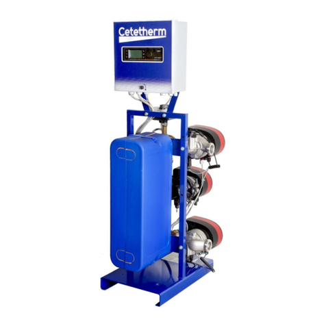
Cetetherm Midi Compact SR144 Manual

DOC1312 Rev:2020-06-01
Installation, service and operating instruction Cetetherm Midi Compact SR144 DHWC
Heating and domestic hot water substation for apartment houses (10-50 apts.)

This manual is published by Cetetherm.
Cetetherm can without further notice make changes and improvements to the content in this manual if it is necessary due to printing
mistakes, wrong information or changes in the hardware or software.
All these types of changes will be included in future release of the manual.
For additional on-line information, latest version of this manual please scan
the qr-code or use the link:
https://www.cetetherm.com/midicompact
QR-code:

Cetetherm Midi Compact RVD144
Installation, service and operating instruction
1
Contents
1General ..................................................................................................................................3
1.1 Comfort......................................................................................................................................................3
1.2 Installation .................................................................................................................................................3
1.3 Long-term security.....................................................................................................................................3
1.4 CE-marking................................................................................................................................................3
1.5 Information about the document................................................................................................................3
1.6 General warnings ......................................................................................................................................4
2Operating instructions..........................................................................................................5
2.1 Operation...................................................................................................................................................5
2.2 Safety equipment/inspection .....................................................................................................................5
3Product overview ..................................................................................................................6
3.1 Midi Compact SR144 ................................................................................................................................6
3.2 Midi Compact SR144 with vertical metering .............................................................................................7
3.3 Midi Compact SR144 with horizontal metering .........................................................................................8
4Installation.............................................................................................................................9
4.1 Unpacking..................................................................................................................................................9
4.2 Preparation ................................................................................................................................................9
4.3 Mounting....................................................................................................................................................9
4.4 Adjustments and settings for start up ..................................................................................................... 10
4.5 Dismantlement........................................................................................................................................ 10
4.6 Commissioning advice ........................................................................................................................... 10
4.7 Measure sketch Midi Compact ............................................................................................................... 11
4.8 Measure sketch Midi Compact with vertical metering ............................................................................ 12
4.9 Measure sketch Midi Compact with horizontal metering........................................................................ 13
5User instruction operator control panel RVD144..............................................................14
5.1 Choosing operating modes .................................................................................................................... 14
5.2 Manual operation.................................................................................................................................... 15
5.3 Set point knob for adjusting the room temperature ................................................................................ 15
5.4 Information on the LCD display .............................................................................................................. 15
5.5 Buttons for settings and adjustment ....................................................................................................... 16
5.5.1 Buttons .............................................................................................................................................. 16
5.5.2 Block skip function............................................................................................................................. 16
5.6 Setting the temperatures in the heating system..................................................................................... 16
5.7 Setting the DHW set point temperature ................................................................................................. 16
5.8 Heating curve ......................................................................................................................................... 17
5.9 Adjusting heating curve/room temperature ............................................................................................ 18
5.10 Set and change heating program ........................................................................................................... 18
5.11 Setting the clock and date ...................................................................................................................... 18
5.12 Reading of temperatures, actual value .................................................................................................. 18
6Settings on the heating engineer’s level ...........................................................................19
6.1 Level settings and access rights ............................................................................................................ 19
6.2 Plant configuration.................................................................................................................................. 19
6.2.1 Pump kick .......................................................................................................................................... 19
6.2.2 Changing between summer and winter time..................................................................................... 19
6.3 Spaceheating.......................................................................................................................................... 20
6.4 Actuator heating circuit ........................................................................................................................... 20
6.5 D.h.w. heating......................................................................................................................................... 20
6.6 Test and display ..................................................................................................................................... 20
6.6.1 Sensor test ........................................................................................................................................ 21
6.6.2 Relay test .......................................................................................................................................... 21
6.6.3 Resetting the heating engineer level................................................................................................. 21
6.6.4 Software version................................................................................................................................ 21
6.7 Reset end-user level .............................................................................................................................. 22
6.8 ModBus communication ......................................................................................................................... 22

Cetetherm Midi Compact RVD144
Installation, service and operating instruction
2
7Troubleshooting..................................................................................................................23
7.1 Standard values and fault indication for RVD144 .................................................................................. 23
7.2 Fault codes on the RVD144 ................................................................................................................... 23
7.2.1 Fault in heating control system ......................................................................................................... 23
8Electrical installation ..........................................................................................................24
8.1 General................................................................................................................................................... 24
8.2 Installation of outdoor temperature sensor............................................................................................. 24
8.3 Electrical circuit diagram EU .................................................................................................................. 25
9Schematic diagram, main components.............................................................................26
9.1 Midi Compact.......................................................................................................................................... 26
9.2 Midi Compact with vertical metering....................................................................................................... 27
9.3 Midi Compact with horizontal metering .................................................................................................. 28
10 Pump settings and pump capacity ....................................................................................29
10.1 General................................................................................................................................................... 29
10.2 DHWC pump Grundfos UPSO 15-55, capacity...................................................................................... 29
10.3 Heating circuit pump Grundfos Magna3 25–100, settings and capacity................................................ 30
10.3.1 Heating circuit pump Grundfos Magna3 25-100, capacity ................................................................ 30
10.3.2 Grundfos Eye operating indications .................................................................................................. 30
11 Service instructions............................................................................................................31
11.1 Service instructions, tap water ............................................................................................................... 31
11.1.1 Tap water temperature too low ......................................................................................................... 31
11.1.2 Tap water temperature too high ........................................................................................................ 31
11.1.3 Hot water temperature unstable........................................................................................................ 31
11.1.4 Noise in the DHWC system............................................................................................................... 32
11.2 Service instructions, heating system ...................................................................................................... 32
11.2.1 Heating system temperature too high or too low .............................................................................. 32
11.2.2 No heating ......................................................................................................................................... 32
11.2.3 Noise in the radiator system.............................................................................................................. 33
11.2.4 Heating temperature unstable........................................................................................................... 33
11.2.5 Heating system often needs topping up............................................................................................ 33
12 Service actions for the installer .........................................................................................34
12.1 Check the function of the hot water valve and actuator ......................................................................... 34
12.2 Check the function of the heating actuator and valve ............................................................................ 35
12.3 Check DHWC pump ............................................................................................................................... 35
12.4 Run the pump manually ......................................................................................................................... 36
12.5 Check the volume take-up and pressure equalizing of the expansion vessel ....................................... 36
13 Maintenance and repairs ....................................................................................................37
13.1 Cleaning the district heating strainer ...................................................................................................... 37
13.2 Clean the heating circuit strainer............................................................................................................ 38
13.3 Change the complete DHWC pump or pump components.................................................................... 38
13.4 Change the complete heating pump or pump components ................................................................... 39
13.5 Change the heating actuator .................................................................................................................. 39
13.6 Change the hot water actuator ............................................................................................................... 40
13.7 Change the heating or hot water valve .................................................................................................. 40
13.8 Change the temperature sensor heating supply and return................................................................... 41
13.9 Change the outdoor temperature sensor ............................................................................................... 41
13.10 Change the expansion vessel ................................................................................................................ 41
14 Options ................................................................................................................................42
14.1 4-point HB metering ............................................................................................................................... 42
15 Operation data and capacity ..............................................................................................43
15.1 Operation data Midi Compact 80............................................................................................................ 43
15.2 Operation data Midi Compact 100.......................................................................................................... 44
15.3 Operation data Midi Compact 160.......................................................................................................... 45
15.4 Operation data Midi Compact 200.......................................................................................................... 46
15.5 Technical data ........................................................................................................................................ 46

Cetetherm Midi Compact RVD144
Installation, service and operating instruction
3
1 General
Cetetherm Midi Compact is a complete, ready-to-install heating network substation for heating and hot water. It
is designed for buildings with a primary connection to a heating network. Cetetherm has years of experience in
heating network technology and has developed Midi Compact with well-planned pipe work and with all
components easily accessible for inspection and possible future servicing.
1.1 Comfort
Midi Compact has fully-automatic temperature control for heating and hot water. The heating is controlled in
relation to desired room temperature. The hot water is controlled and maintained at the desired temperature.
1.2 Installation
Before installation this manual must be read.
Well planned pipe work and readymade electrical wiring make installation very simple. A pre-programmed
controller and plug-and-socket connection provide further simplification, so that the substation can be started
without delay. The Midi Compact is designed to be placed on the floor.
1.3 Long-term security
All the plates and pipes in the heat exchanger are made of acid-resistant stainless steel for long life. All
components are adjusted together and undergo thorough function testing in accordance with ISO 9001:2015
quality assurance system.
For future servicing requirements, all components are easily accessible and individually replaceable.
1.4 CE-marking
Midi Compact is CE-marked to certify that the substation conforms to international safety regulations. To
maintain the validity of the CE marking, only identical replacement parts must be used.
1.5 Information about the document
All pictures in this document are general images.
Midi Compact is available in different models and levels of equipment.

Cetetherm Midi Compact RVD144
Installation, service and operating instruction
4
1.6 General warnings
The installation work must be carried out by an authorized installation contractor. Before the
system is taken into operation, it must be pressure tested in accordance with relevant regulations.
The temperature and the pressure of the district heating water are very high. Only duly qualified
technicians can work with the district heating substation. Incorrect operation may cause serious
personal injury and result in damage to the building.
If the hot water temperature is set too high, people may be scalded. If the hot water temperature is
set too low, unwanted bacteriological growth may occur in the hot water system. This can result in
serious personal injury.
Parts of the Midi Compact may get very hot and should not be touched.
Before the substation is connected to the electrical supply, make sure that the secondary heating
system is topped up with water. Starting up the system without water will damage the circulation
pump.
The substation comes prepared with an electrical plug to be connected to the main supply. The
strain relief clips of the cable must be fitted to avoid damage. If necessary, the plug-and-socket
connection can be replaced with a permanent installation with an all-pole isolate switch. This must
be carried out by a duly qualified electrician.
When starting up the district heating substation: To avoid the risk of scalding, make sure that no-
one draws any hot water until the hot water temperature has been adjusted.
Start district heating circulation by first opening the valve in the district heating supply and then
return lines, to avoid pollutions in the system. Open the valves slowly to avoid pressure surges.
Do the same way with the heating circuit, first open the valve for heating return then supply.
Do not shut of the electrical supply to the operator control panel. This will damage the circulation
pump, valves, actuators etc.
The heating station should be placed in a locked space, non-accessible for unauthorized
personnel.

Cetetherm Midi Compact RVD144
Installation, service and operating instruction
5
2 Operating instructions
2.1 Operation
The temperature and pressure of the incoming heating network water from the culvert network are very high.
For this reason, only the heat from this water is used. The heating network water does not enter the heating
and hot water systems of the building.
The heat from the heating network water is transferred to the heating and hot water systems of the building in
the heat exchangers. The heat is transferred through thin plates of acid-resistant stainless steel which keep the
heating network water completely separated from the systems in the building.
Midi Compact has automatic temperature control for heating and hot water. The heating circuit is controlled in
relation to outdoor temperature (option) and/or desired room temperature by means of a controller and
temperature sensor. When no heat is needed, the circulation pump in the heating circuit stops automatically,
but is started regularly to make sure that it does not seize up during long idle periods. The hot water
temperature is controlled by a temperature control system which is set to about 55 ºC.
After adjustment, the Midi Compact operates completely automatically. However, in hard water areas it is
advisable to be attentive and to remedy any faults in good time if the temperature of the hot water is too high;
otherwise the risk of lime deposits in the heat exchanger may increase.
2.2 Safety equipment/inspection
•Daily inspection to check for leaks from pipes or components.
•Weekly inspection to make sure that the operation of the heating and hot water control systems is
stable and that the temperature does not fluctuate. Temperature hunting causes unnecessary wear
of valves, actuators and heat exchangers.
•Every three months check the safety valves and the pressure in the heating system.
To check the operation of a safety valve, turn its wheel until water escapes from the waste pipe of the valve,
then close the wheel quickly. Occasionally a safety valve may open automatically to release excess pressure.
After a safety valve has been open it is important that it closes properly and does not drip.
Hot water temperature in apartments or one family houses can be set to about 55°C. If the temperature is set
too high, there is a risk of scalding. Setting the hot water temperature too low may result in unwanted
bacteriological growth in the hot water system.
For setting and (if necessary) fine adjustment of the heating and hot water temperatures,
see chapter 4 User instruction operator control panel .
The heating system is topped up via the topping up valve. Be sure to close the valve when the correct pressure
is reached. The water used to top up the system contains oxygen and may cause corrosion in the system. For
this reason, the system should be topped up as seldom as possible, at most once
If a joining must be loosened and then re-installed, for example when installing the substation or when
replacing a filter unit, the joining gaskets should be exchanged to prevent leaks.

Cetetherm Midi Compact RVD144
Installation, service and operating instruction
6
3 Product overview
3.1 Midi Compact SR144
1
Heat exchanger heat
20
Topping up X2
2
Heat exchanger DHW
21
Hose
3
Control center
22
Draining valve, heat supply
4
Control valve, heating
23
Shut off valve, heat supply
5
Actuator, heating
24
Pump, heating
6
Control valve, DHW
25
Safety valve, heating
7
Actuator, DHW
26
Shut off valve, heat return
8
Temp.sensor, outdoor (not in picture)
27
Strainer, heat return
9
Temp.sensor, heating Supply
28
Connection, expansion vessel
10
Temp.sensor, DHW Supply
29
Draining valve, DH-Supply
11
Shut off valve, DHW
36
Temp.sensor heating return
12
Balancing valve, DHWC
37
DH Return
13
Pump, DHWC
38
CW
14
None return valve, DHWC
39
DHWC
15
Shut off valve, DHWC
40
DHW
16
Shut off valve, CW
41
DH supply
17
None return valve, CW
42
Heat Supply
18
Safety valve, CW
43
Heat Return
19
Draining valve, DH-Supply

Cetetherm Midi Compact RVD144
Installation, service and operating instruction
7
3.2 Midi Compact SR144 with vertical metering
1
Heat exchanger heat
22
Draining valve, heat supply
2
Heat exchanger DHW
23
Shut off valve, heat supply
3
Control center
24
Pump, heating
4
Control valve, heating
25
Safety valve, heating
5
Actuator, heating
26
Shut off valve, heat return
6
Control valve, DHW
27
Strainer, heat return
7
Actuator, DHW
28
Connection, expansion vessel
8
Temp.sensor, outdoor (not in picture)
29
Draining valve, DH-Supply
9
Temp.sensor, heating Supply
30
Strainer, DH-Supply
10
Temp.sensor, DHW Supply
31
Heat meter dummy
11
Shut off valve, DHW
32
Connection energy meter sensor primary supply
12
Balancing valve, DHWC
33
Connection energy meter sensor primary return
13
Pump, DHWC
36
Temp.sensor heating return
14
None return valve, DHWC
37
DH Return
15
Shut off valve, DHWC
38
CW
16
Shut off valve, CW
39
DHWC
17
None return valve, CW
40
DHW
18
Safety valve, CW
41
DH supply
19
Draining valve, DH-Supply
42
Heat Supply
20
Topping up x2
43
Heat Return
21
Hose

Cetetherm Midi Compact RVD144
Installation, service and operating instruction
8
3.3 Midi Compact SR144 with horizontal metering
1
Heat exchanger heat
23
Shut off valve, heat supply
2
Heat exchanger DHW
24
Pump, heating
3
Control center
25
Safety valve, heating
4
Control valve, heating
26
Shut off valve, heat return
5
Actuator, heating
27
Strainer, heat return
6
Control valve, DHW
28
Connection, expansion vessel
7
Actuator, DHW
29
Draining valve, DH-Supply
8
Temp.sensor, outdoor (not in picture)
30
Strainer, DH-Supply
9
Temp.sensor, heating Supply
31
Heat meter dummy
10
Temp.sensor, DHW Supply
32
Connection energy meter sensor primary supply
11
Shut off valve, DHW
33
Connection energy meter sensor primary return
12
Balancing valve, DHWC
34
Connection 3-point HB metering
13
Pump, DHWC
35
Pressure gauge connection
14
None return valve, DHWC
36
Temp.sensor heating return
15
Shut off valve, DHWC
37
DH Return
16
Shut off valve, CW
38
CW
17
None return valve, CW
39
DHWC
18
Safety valve, CW
40
DHW
19
Draining valve, DH-Supply
41
DH supply
20
Topping up x2
42
Heat Supply
21
Hose
43
Heat Return
22
Draining valve, heat supply

Cetetherm Midi Compact RVD144
Installation, service and operating instruction
9
4 Installation
4.1 Unpacking
•Remove the transport packaging and check that the product has not been damaged in transit and that
the consignment agrees with the specifications.
•When lifting the unit, take care not to apply stress to pipes and heat exchangers as this may weaken
them. Lift the unit in the frame; avoid lifting the unit by holding the heat exchangers. Use pallet lift
where applicable, if using back straps these should be attached to the substructure of the substation.
Note: Risk of injury lifting heavy objects.
4.2 Preparation
•Choose a suitable installation area in accordance with official regulations.
The system may generate sounds during operation caused by pumps, regulators systems, flows etc.
This should be taken into consideration during installation of the unit, so that possible operational
sounds affect the surroundings as little as possible.
•Check the applicable regulations of the district heating supplier. The available differential pressure
should be at least 100 kPa and at most 600 kPa.
Where the differential pressure is higher, a differential pressure controller should be added to the
installation.
•Flush heating and hot water systems.
4.3 Mounting
•Place the substation so that connections, adjustment equipment and safety valves are easily
accessible.
•Mount the shutoff valves on district heating supply and return. Shutoff valves are not supplied.
•Connect the pipe works to the connection points see 4.7-4.9.
•When executing hot work on or close by the substation, all incendiary components should be
demounted and removed.
•Take rules and instructions regarding hot work into account.
•Connecting pipes shall be suspended so that their weight does not stress the unit.
•All connecting pipes within and connecting to the units system shall be insulated according to
standards and regulations.
•Drainage pipes from safety valves must be taken to a floor gully.
•Energy meters must be installed at a prepared location, replacing a gauge block, or following the
instructions of the energy supplier.
•Retighten all connections, including those made at the factory. If connections need retightening after
the installation has been taken into service, the system should be depressurised before retightening. If
the system is not depressurised before retightening, gaskets will be damaged.
•Required expansion volume shall be installed and provided with adequate pre-charge before start up.
•Remount plugs in drain valves after possible draining of circuit.
•Mount the outdoor temperature sensor on the north side of the building, 2 meters above the ground, or
higher. For installation of the outdoor temperature sensor, see 8.2.

Cetetherm Midi Compact RVD144
Installation, service and operating instruction
10
4.4 Adjustments and settings for start up
•Open up incoming cold water supply and fill the service water and heating circuits, bleeding off any
trapped air.
•Check the operation and opening pressures of the safety valves.
•Adjust the hot water temperature by having a hot water tap open at normal flow rate for a time.
Measure the temperature at the draw-off point with a thermometer. The temperature should be
approximately 55°C. It takes about 20 seconds to get stable tap water temperature. See
troubleshooting chart for adjusting hot water temperature, 11.1.1 Tap water temperature too low.
NOTE: Make sure that no cold water is mixed with hot water while making this adjustment.
•Start the heating circulation pump at the strongest flow setting during some minutes. The pressure
should be at least 1000 kPa during winter and at least 600kPA during summer.
•Set the pump capacity of the heating circulation pump and the DHWC-pump according to
chapter 10 Pump settings and pump capacity .Use the lowest setting that manages the heating
demand for best electrical efficiency.
•Make any necessary adjustment of the heating curve of the control and regulating equipment.
Information about the controller can be found in this document.
•Set time, date and hot water temperature on the adjustment center.
•The property owner must be informed on how to operate, adjust and maintain the unit. It is overly
important to inform about the safety systems and the risks associated with the high pressure and
temperature of the district heating systems water supply.
4.5 Dismantlement
When the time comes for the substation to be dismantled and scrapped it must be disposed of in the correct
manner in accordance with local or national regulations.
4.6 Commissioning advice
The controller has been set at the factory. If any function needs tuning, values can be changed with reference
to this manual for parameter setting. Initially, the commissioning process should be carried out with the factory
settings. The parameter settings need tuning only if the district heat terminal does not function accordingly.

Cetetherm Midi Compact RVD144
Installation, service and operating instruction
11
4.7 Measure sketch Midi Compact
Picture 1

Cetetherm Midi Compact RVD144
Installation, service and operating instruction
12
4.8 Measure sketch Midi Compact with vertical metering
Picture 2

Cetetherm Midi Compact RVD144
Installation, service and operating instruction
13
4.9 Measure sketch Midi Compact with horizontal metering
Picture 3

Cetetherm Midi Compact RVD144
Installation, service and operating instruction
14
5 User instruction operator control panel RVD144
Picture 4
1. Operating mode buttons
2. Display (LCD)
3. Buttons for selecting operating lines
4. Button for manual operation ON / OFF
5. Button for DHW heating ON / OFF
6. Buttons for making readjustments of values
7. Setting knob for nominal room temperature set point
5.1 Choosing operating modes
The following operating mode buttons are available:
•3 buttons for selecting the heating circuit´s operating mode
•1 button for d.h.w. heating
The required operating mode is activated by pressing the respective button. Each of the buttons contains an
LED that will light to indicate the currently active operating mode.
Stand-by
•Heating operation OFF
•Frost protection is ensured
Automatic operation
•Automatic heating operation, changeover between nominal and reduced temperature according to the
time program
•ECO function with needs oriented connection and disconnection of the heating system as a function of
the outdoor temperature and the building's heat storage capacity. ECO-saving automatic closes the
control valve and stops the heating pump. The pump is run regularly.
•Frost protection is ensured
Continuous operation
•Heating operation with no time program
•Heating to the room temperature adjusted with the setting knob
•Frost protection is ensured
•ECO-saving automatic is not active and the heating pump runs continuously.
D.h.w. heating ON/OFF
•ON (button lit):
D.h.w. is heated independently of the heating circuit’s operating mode and control
•OFF (button dark):
No d.h.w. heating; circulating pump switches off, frost protection is ensured

Cetetherm Midi Compact RVD144
Installation, service and operating instruction
15
5.2 Manual operation
Manual operation is activated by pressing a button. It is indicated by an LED. At the same time, the LEDs in the
operating mode buttons extinguish. Manual operation is quit by pressing the same button again or by pressing
any of the operating mode buttons.
Manual operation
•No operating mode
•Heating circuit pump and d.h.w. pump are running.
•The control valve in the primary circuit can be manually operated with the setting buttons, or with the
handle on the valve
The control valve for domestic hot water should NEVER be operated by hand.
5.3 Set point knob for adjusting the room temperature
The knob is used to make manual adjustments of the nominal room temperature set point.
Its scale gives the room temperature in °C.
Turning the knob produces a parallel displacement of the heating curve, the room temperature will increase or
decrease according to the room temperature scale on the adjusting knob.
5.4 Information on the LCD display
If the bar is alight under Explanation
Heating is maintained at normal set point
temperature
(preset on adjusting knob)
Heating is maintained at lowered temperature
The display shows Explanation
Heating is maintained at freezing protection
temperature
ECO No heating is needed. Pump stop activated
┌ or ┘ A limit function is active
Hot water with solar
BUS The controller is connected to ModBus

Cetetherm Midi Compact RVD144
Installation, service and operating instruction
16
5.5 Buttons for settings and adjustment
The entry or readjustment of all setting parameters, activation of optional functions and reading of actual values
and states is made according to the operating line principle. An operating line with its number is assigned to
each parameter, actual value and function that can be selected.
One pair of buttons is used to select an operating line and one pair to readjust the display.
5.5.1 Buttons
Buttons
Procedure
Effect
Line selection buttons
Press
Selects the next lower or higher
operating line
Setting buttons
Press
Decreases or increases the
displayed value
The set value will be adopted
•when selecting the next operating line, that is, by pressing a line selection button or , or
•by pressing an operating mode button
If entry of --.- or --:-- is required, setting button or must be pressed until the required display appears.
Then, the display shows constantly --.- or --:-- .
5.5.2 Block skip function
The operating lines are grouped as blocks. To select an individual operating line in a block as quickly as
possible, the other lines can be skipped. This is made by using a two button combinations:
Procedure
Effect
Keep depressed and press or .
Selects the next higher or lower block
5.6 Setting the temperatures in the heating system
1. Use the setting knob for the required temperature set point.
The setting will be active:
– On automatic operation during the heating periods that have been entered into the heating program
– Constantly on continuous operation
2. Use the buttons to set other temperatures and the required control curve as follows:
Line
Function, parameter
Unit
Factory setting
Range
1
Current nominal room temperature set point
Display function
2
Reduced room temperature set point
°C
18
variable*
3
Frost protection/holiday mode set point
°C
8
8…variable*
5
Heating curve slope
1,25
0,25…4,0
* variable setting
5.7 Setting the DHW set point temperature
Line
Function, parameter
Unit
Factory setting
Range
41
DHW normal set point
°C
55
50°C - 65°C

Cetetherm Midi Compact RVD144
Installation, service and operating instruction
17
5.8 Heating curve
Picture 5
S Slope
TAM Composite outside temperature
TV Flow temperature
Set the correct heating curve based on the supply temperature and Composite Outside Temperature (COT).
Picture 11 shows examples of different heating curves that can be set and adjusted according to COT and the
supply temperature.
It is possible to choose at curve that lies between the default heating curves.
Default value is 1.25 for the heating curve, this fits most new houses.
Adjust the slope of the heating curve on the program line .
The graph for heating curves is specific to the building and must be adjusted individually during the first heating
season.
NOTE! For a house with under floor heating, the value in the graph should be around 0.5. Always check with
the under floor heating supplier.
With weather-compensated supply temperature, the supply temperature set point follows the heating curve.

Cetetherm Midi Compact RVD144
Installation, service and operating instruction
18
5.9 Adjusting heating curve/room temperature
Mainly in mild weather:
Use the adjusting knob to adjust the room temperature .
Mainly in cold weather:
Adjust the slope of the heating curve on the program line :
– The room temperature is too high: Lower the slope by about 0.5.
– The room temperature is too low: Increase the slope by about 0.5.
Mainly at night:
Adjust the temperature for lowered set point on the program line .
Wait for two days after every room temperature adjustment to allow the control system to stabilize.
5.10 Set and change heating program
The heating program is set on line 6 and the heating periods are set on line 7-12.
The heating program can be for the whole week or individual for each weekday. The heating program can be
set to 3 heating periods per day.
First enter the times for the entire week and then change weekdays 6 and 7 as required.
The settings are sorted and overlapping heating periods combined.
When setting --:-- for the start or the end, the heating period will be negated.
Line
Function, parameter
Factory setting (range)
Unit
6
Weekday f or entering the heating program
Current weekday (1...7/1-7)
1…7, 1-7
1= Monday
2= Tuesday
1-7= entire week
7
Heating period 1 start
06:00 (--:--/00:00...24:00)
hh:mm
8
Heating period 1 end
22:00 (--:--/00:00...24:00)
hh:mm
9
Heating period 2 start
--:-- (--:--/00:00...24:00)
hh:mm
10
Heating period 2 end
--:-- (--:--/00:00...24:00)
hh:mm
11
Heating period 3 start
--:-- (--:--/00:00...24:00)
hh:mm
12
Heating period 3 end
--:-- (--:--/00:00...24:00)
hh:mm
5.11 Setting the clock and date
Line
Function, parameter
Unit
Factory
setting
13
Time of day
hh:mm
(00:00...23:59)
14
Weekday
d
Display
function
15
Date
dd.MM
(01.01...31.12)
16
Year
yyyy
(2009...2099)
5.12 Reading of temperatures, actual value
Line
Function, parameter
Unit
24
Room temperature
°C
25
Outside temperature
°C
26
D.h.w. temperature
°C
27
Flow temperature heating circuit
°C
This manual suits for next models
4
Table of contents
Other Cetetherm Water System manuals
Popular Water System manuals by other brands

Eau Flow
Eau Flow 505 installation manual

Apec Water
Apec Water ROES-UV75 Installation instructions & owner's manual

EasyWater
EasyWater RevitaLife owner's guide

BLUGARDA
BLUGARDA BluClear 18 manual

OSMOSEA
OSMOSEA EVO 300 Instructions for installation, use and maintenance manual

Tecnogas
Tecnogas ProCLEAN STORMY Operation manual

FLOWMARK
FLOWMARK DS-3 Installation & operation manual

Zip
Zip HydroTap G4 Installation and operating instructions

Grunbeck
Grunbeck desaliQ Operation manual

Zip
Zip FlushMaster Pearl Installation & maintenance instructions

Global Industrial
Global Industrial 761219 user manual

MCDonald
MCDonald Powerflow instructions